B 17 - Electric fence for animals BlackGuard - Free user manual and instructions
Find the device manual for free B 17 BlackGuard in PDF.

| Product Type | Animal fence energizer |
| Brand | BlackGuard |
| Model | B 17 |
| Main power supply | 9V alkaline battery (included) or 12V battery (optional) |
| Operating modes | EXTREM (high power) and ECO (energy saving) |
| Minimum output voltage | 2500 V on the fence |
| Light indicator | Flashing indicator light (green/red depending on status) |
| Approximate dimensions | 150 x 100 x 50 mm |
| Approximate weight | 350 g |
| Housing material | UV-resistant plastic |
| Mounting | Vertical mounting on non-flammable wall or on post (post included) |
| Ground electrode | Not included, must be driven at least 1 m into the ground |
| Warranty | 3 years (according to conditions in the manual) |
| Discharge protection | Yes, in 12V battery mode (automatic shutdown below 11V) |
| Pulse frequency | Approximately 1 pulse per second |
| Mandatory daily check | Visual inspection and voltage measurement ≥ 2500V |
| Maintenance | Clean with a dry soft cloth. Do not use solvents. |
| Repairability | Repairs reserved for an authorized specialist (after-sales service or manufacturer) |
| Spare parts available | High voltage cables, insulators, ground rods (accessories) |
| Standards and certifications | CE compliant, directive EN 60335-2-76 |
| Outdoor use | Device must be protected from rain and direct sunlight (except solar models) |
| Warning signs | Required along public roads (not included) |
Frequently Asked Questions - B 17 BlackGuard
User questions about B 17 BlackGuard
0 question about this device. Answer the ones you know or ask your own.
Ask a new question about this device
Download the instructions for your Electric fence for animals in PDF format for free! Find your manual B 17 - BlackGuard and take your electronic device back in hand. On this page are published all the documents necessary for the use of your device. B 17 by BlackGuard.
USER MANUAL B 17 BlackGuard
The author thanks the International Electrotechnical Commission (IEC) for permission to reproduce Information from its International Publication 60335-2-76 ed.2.0 (2002). All such extracts are copyright of IEC, Geneva, Switzerland. All rights reserved. Further information on the IEC is available from www.iec.ch. IEC has no responsibility for the placement and context in which the extracts and contents are reproduced by the author, nor is IEC in any way responsible for the other content or accuracy therein.
Figure 1
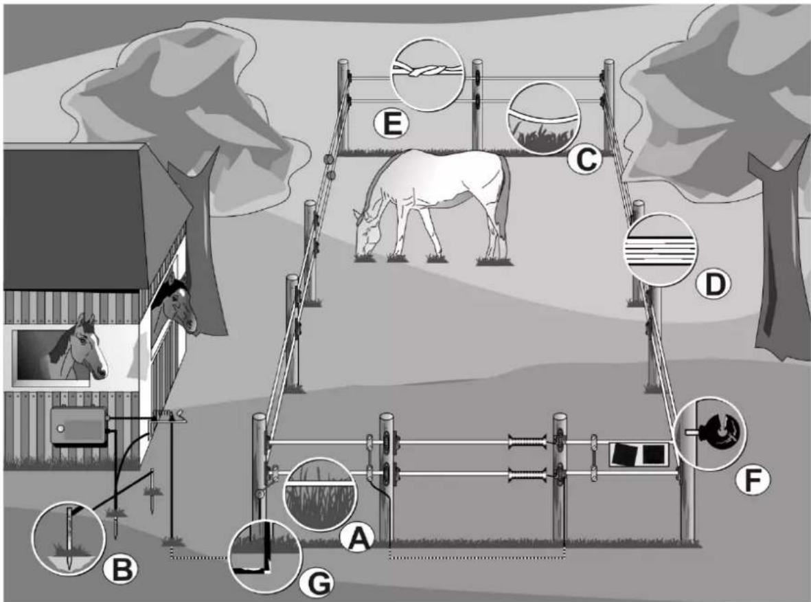
Figure 2
SERVICE-Adressen:
We congratulate you on the purchase of your electric fence unit. You have acquired a high-quality appliance, which corresponds to the current safety regulations as well as to the relevant EC-guidelines (CE). With this appliance, you can improve the security of your fence system. Environmental conditions and incorrect installation can influence your fence system; therefore absolute security cannot be guaranteed. For this reason the seller gives no assurance that the fence system is safe against outbreak. To achieve the best results and correct installation please read the following and the enclosed specific instruction manual.
Installation of an electric fence system : (Figure 1)
| 1 Electric fence appliance | 10 Gate component | |||
| 2 Earthing cable | 11 | Warning-plate | ||
| 3 Permanent fencing post | 12 Corner insulator | |||
| 4 Rust-protected grounding rod | 13 Distance insulator | |||
| 5 Underground cable high volt. resist. | 14 Tape, wire | |||
| 6 On / Off switch | 15 | Mobile pos | ||
| 7 Fence connecting cable | 16 Wire tensioner | |||
| 8 Connecting cable | 17 | Fence | connector | |
| 9 Gate handle system | 18 Lightning protection |
Safety instructions :
Please follow this instruction exactly and store it well when not in use.
Electric fences shall be installed and operated so that they cause no electrical hazard to persons, animals or their surroundings.
This appliance is not intended for use by persons (including children) with reduced physical, sensory or mental capabilities, or lack of experience and knowledge, unless they have been given supervision or instruction concerning use of the appliance by a person responsible for their safety. Children should be supervised to ensure that they do not play with the appliance. (A2:06)
Contact with electrified fences must be avoided, especially with the head, neck or upper body. Do not climb on, over or through the fence. A gate or other type of passage must be used to pass through the fence.
Electric fence constructions, which are likely to lead to the entanglement of animals or persons, shall be avoided.
An electric fence shall not be supplied from two (or more) different energizers or from independent fence circuits of the same energizer.
For any two (or more) different electric fences, each supplied from a different energizer independently timed, the distance between the wires of the two electric fences shall be at least 2.5 m. If this gap is to be closed, this shall be effected by means of electrically non-conductive material or an isolated metal barrier.
An energizer shall not electrify barbed wire or razor wire.
Any part of an electric fence which is installed along a public road or public thoroughfare shall be identified at frequent intervals by warning plates securely fastened to the fence posts or firmly clamped to the fence wires. The background colour of both sides of the warning plate shall be yellow. The inscription on both sides of the warning plate shall be black and shall be the substance of TAKE
CARE – ELECTRIC FENCE or the symbol 🚗. The size of the warning plates shall be at least 200 mm 100 mm.
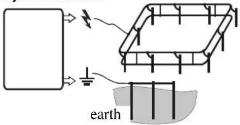
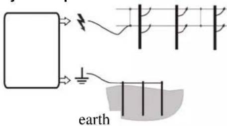
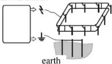
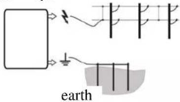
A distance of at least 10 m shall be maintained between the energizer earth electrode and any other earthing system such as the power supply system protective earth or the telecommunication system earth.
Except for low output battery-operated energizers, the energizer earth electrode shall penetrate the ground to a depth of at least 1 m. Care shall be taken to avoid any damage to cables or pipelines.
Connecting leads that run inside buildings shall be effectively insulated from the earthed structural parts of the building. This may be achieved by using insulated high voltage cable.
Connecting leads that run underground shall be run in a conduit of insulating material or else insulated high voltage cable shall be used. Care shall be taken to avoid animal or mechanical damage to the connecting leads.
Connecting leads shall not be installed in the same conduit as the mains supply wiring, communication cables or data cables.
Connecting leads and electric fence wires shall not cross above overhead power or communication lines.
Crossings with overhead power lines shall be avoided wherever possible. If such a crossing cannot be avoided, it shall be made underneath the power line and as near as possible at right angles to it.
If connecting leads and electric fence wires are installed near an overhead power line, the clearances shall be not less than those shown in below-mentioned table.
Power line voltage Clearance
≤ 1.000 volts 3 meter
1.000 ≤ 33.000 volts 4 meter
33.000 volts 8 meter
If connecting leads and electric fence wires are installed near an overhead power line, their height above the ground shall not exceed 3 m.
This height applies either side of the orthogonal projection of the outermost conductors of the power line on the ground surface, for a distance of
- 2 m for power lines operating at a nominal voltage not exceeding 1 000 V;
- 15 m for power lines operating at a nominal voltage exceeding 1 000 V.
If connecting leads and electric fence wires are installed near a telecommunication line or a telecommunication cable, their distance to the line or the cable shall not exceed 2 m.
Electric fences intended for deterring birds, household pet containment or training animals such as cows need only be supplied from low output energizers to obtain satisfactory and safe performance.
In electric fences intended for deterring birds from roosting on buildings, no electric fence wire shall be connected to the energizer earth electrode. A warning plate, as described above, shall be fitted to every point where persons may gain ready access to the conductors.
A non-electrified fence incorporating barbed wire or razor wire may be used to support one or more off-set electrified wires of an electric fence. The supporting devices for the electrified wires shall be constructed so as to ensure that these wires are positioned at a minimum distance of 150 mm from the vertical plane of the non-electrified wires. The barbed wire and razor wire shall be earthed at regular intervals.
Where an electric fence crosses a public pathway, a non-electrified gate shall be incorporated in the electric fence at that point or a crossing by means of a stile shall be provided. At any such crossing, the adjacent electrified wires shall carry warning plates as described above.
Electric fence-appliances have to be driven in accordance with the position described in the instruction manual.
Install the energizer preferably in a location not exposed to direct sunlight (except solar devices) and rain. All cables and wires for line and fence connection must be kept distant from any inflammable material. The mounting surface itself must consist of non-inflammable material.
The installation of the electric fence-appliance has to be done onto inflammable floor. To avoid any lightning-damages, the fence wire at the building has to be taken over an overvoltage protection-equipment with a thrush and a spark plug gap which has to be mounted on incombustible material on the outside wall of the building. This has to be done before any connection to the electric fence-appliance. This applies also to combi devices, if these are powered by a mains adaptor.
Don't connect to existing earth wires of the power supply-network.
Any user of electric fence systems is legally indebted to control the fence-appliance and the fence system regularly, in accordance with the conditions of use, at least once per day.
- visual check of the appliance and the fence system
- measurement of the minimum voltage of 2500V at each point of the fence
For using an electric fence-appliance in a barn, only specially constructed appliances may be used.
Power surges triggered by thunderstorms can damage the insulation on electric fence devices. In such cases, mains voltage can get through to the electric fence and thereby seriously endanger humans and animals.
In general we therefore recommend connecting mains-operated electronic fence devices only to a public power supply protected by a residual current circuit breaker with a maximum 30mA trip current.
It is also sensible during thunderstorms to disconnect mains-operated electric fence devices from the electricity grid, and also, if possible, from the fence.
If no mains supply with circuit breaker protection is available, and if the device was connected to the fence system during a thunderstorm, it must be properly checked before being put back into service. That requires at least a mains connection with a residual current circuit breaker.
For testing, the earthing connection on the device is connected to the protective earth of the mains supply grid, and then the power plug of the device is connected to the socket with residual current protection. If the device clocks correctly, and shows no deviation from normal behaviour, the device can again be connected to the fence. If however the circuit breaker trips again when the device is connected, the device must not be used any more, and must be repaired in a specialist workshop.
If the connecting cable of this device is damaged, the manufacturer, his after-sales service or a similarly qualified person must replace it in order to avoid hazard. Services and repairs only by authorized experts!
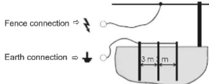
Earthing
The correct earthing is extremely important, as the complete function of the appliance depends on it.
After the complete installation, knock a rust-protected grounding rod into the ground up to the limit stop at a place with preferably high, continuous moisture.
If necessary in dry areas or, grounds with low conductivity, one or more additional earth rods have to be used (length at about 1 m). These earth rods have to be knocked into the ground at a distance of approximately 3 m from each other.
Put to service
- The enclosed specific instruction manual for the appliance has to be read before being put to service.
- Always make sure that the appliance is switched off as well as disconnected from the network before being connected to the energizer unit.
- Connection plan of the electric fence appliance:
- With battery-fencers, pay attention on the right polarity at connection with the battery. black = negative; red = positive.
230V\~:
Operation only at 230V mains voltage +10/-15%, frequency 50 or 60 Hz, pure sine form. Operation on inverters (solar power systems, etc.) will result in device failure. Damage which occurs from operation on inverters is excluded from the guarantee.
Maintenance of battery and accumulator
The voltage of the batteries and accumulators have to be checked regularly with an as exact as possible measuring instrument.
9 volt dry-battery ( 9V appliances ):
- Before using the battery, the sticker which closes the air- openings, has to be removed.
Only now, the battery is ready for use. - Attention: even a discharged alkaline 9V-battery can reach, some time after the switch off of the appliance, an almost normal voltage of 7.5 – 8.5 volts. Nevertheless the battery is spent and should be detoxified, as with normal drive the voltage will again fall under 4,5V (ideal value: 7.8 - 9V, during the current operation!).
- Various 9 V appliances can also be driven with 12 volt. Important: In this case a corresponding adapter-cable from the manufacturer has to be used and the 12V hints have to be heeded.
12 volt accumulator ( 12V appliances ):
- A 12V lead accumulator is already deeply discharged with the low burden which is typical for electric fencers, at a voltage of 11.9V and should be reloaded without any delay. In order to guarantee an optimum lifetime we advise a recharge of the accumulator already at a voltage of 12.1 volt.
• Also with an only short-term discharge under 11V a normal lead-accumulator will be durably damaged. - Through overload, what means further charging of the accumulator after attainment of a maximum voltage of 13.8V, not only the accumulator will be damaged, but also acid of the accumulator may tread out which can destroy the electric fencer (ideal value: 12.6 – 13.8V).
- By no means, an accumulator may be connected to the appliance for a longer time without any control!
- 12V accumulators may only be reloaded in aired rooms with a suitable charger.
- In case of longer intermissions (eg.: winter-intermission) the accumulators have to be connected to a charger which is equipped with a maintenance-grade. Otherwise the accumulators could be durably damaged because of their self-discharge.
- Appliances which run with a solar-module > 25 W require an additional solar-regulator.
- Appliances which run with a solar-module / mains-adapter in combination with a 12V gel-accumulator require an additional solar-regulator.
If the batteries as well as accumulators are discharged, they have to be properly detoxified!
Warranty
Beside the statutory guarantees we give a warranty according to the following conditions:
- Warranty starts with date of purchase. Warranty claims will only be acknowledged together with the invoice or the payment voucher. Costs for shipping and return are for account of the buyer. Warranty repairs will be free of charge. We reserve the right to supply an other equivalent appliance.
- Warranty is only valid with appropriate use and according to the instruction manual and is deemed invalid with unauthorized repairs and use as well as with use of non-genuine spare parts.
- We shall rectify any faults caused by material defects or manufacturing faults, by repairing or replacing the device at no charge and at our discrepancy.
- Any repairs or spare part deliveries will not extend the original warranty durage.
- Duration of warranty as well as the address of the warrantors please find on the enclosed specific instruction manual.
- Damaged through overvoltage, Accumulators of any construction or leaking acid are excluded from any warranty.
Possible sources of errors: (Figure 2)
| Pos. | Sources of errors Debugging | |
| A | Derivative due to growth at the fence! Remove growth (mow / cut)! | |
| B | Bad earthing, too short earthing rod, rust, dry ground | Knock in the grounding rod completely! Use several long grounding rods and connect them with each other! |
| C | Conductive material at the ground (eg.: tape / wire break, not stretched)! | Repair fence, stretch conductive material! |
| D | Conductive material has bad quality (thin conduction wire, high resistance) | Use high-quality conductors with low resistance and thick conduction wires. In case of wide tapes, pay attention on the conductor connections! |
| E | Conductive material knoted! | Use corresponding special-connectors for wire / tape / rope! |
| F | Insulator comes through! Exchange damaged and weather beaten insulators! | |
| G | Derivative or short circuit in the fence wire! | Never use an ordinary moisture resistant cable or something like this for connection!Use high voltage cable in all cases! |
| H | Fence is too long!Has the right unit been chosen for this use? | Use the correct unit corresponding to the length of the fence and to the type of animal – if necessary; discuss it with your stockist. |
| I | Does the electric fence unit work? | Hang the unit from the fence, then switch on!If the LED blinks, the unit is ok, if it does not, the unit is damaged (contact the dealer)!Pay attention of the polarity at batteries and accumulators! |
Operating Instructions
 |  Possible current sources:-12 Volt-special -230 Volt mains-adapter,for indoor use only (Art.-Nr.: 371023)This energizer shall not be used as an animal trainer (inside a barn). Possible current sources:-12 Volt-special -230 Volt mains-adapter,for indoor use only (Art.-Nr.: 371023)This energizer shall not be used as an animal trainer (inside a barn). | 1 | Warning lights(green and red) |
| 2 | Fence connection | ||
| 3 | Earth connection | ||
| 4 | 12V battery connectioncable/ 230V mainsadapter | ||
| 5 | Fastening hole |
Description of function
Put the equipment into service by connecting to fence and earth first, then to a 12 V battery. Please check for correct polarity of the connection (red="+" , black = "-").
• If only the green light is flashing, the equipment and battery are working correctly.
- If the red and green lights are flashing simultaneously, the battery is in a low charge state. Although pulses are still emitted to the fence, the back-up battery should be recharged in the very near future
- If only the red light is flashing, then the deep discharge protection has kicked in (This is necessary to protect the battery from permanent damage). The equipment no longer emits pulses to the electric fence. Recharge or replace the battery immediately.
- If neither of the two lights is flashing, the equipment is not getting any current from the battery (Check the battery connection for correct polarity and the battery for sufficient voltage. If both are o.k., have the unit checked by an expert.
- The equipment gives no warning if the electric fence is faulty.
Important Notes:
The appliance must be installed in vertical position with the battery connecting cable at the bottom and, if possible, protected against rain, see above picture. In case of wall mounting, the appliance must be mounted against a fireproof wall. For outdoor installation, a zinc-plated metal casing can be used. This accessory (part No. 44656) protects the appliance and simultaneously protects the accumulator.
Ensure correct polarity when connecting the battery (red + and black -).
!!! Attention: Earthing rods are not included in the scope of supply!!!
Any user of electric fence systems is legally indebted to control the fence-appliance and the fence system regularly, in accordance with the conditions of use, at least once per day.
- visual check of the appliance and the fence system
- measurement of the minimum voltage of 2500V at each point of the fence
This equipment carries a 3-year warranty in accordance with our Warranty Terms & Conditions! Please see the attached Operating Instructions for safety tips, earthing, commissioning, battery care, warranty terms and conditions, and potential fault sources!
Operating Instructions
| 12456 | 3 Possible current sources:-12 Volt- special 230 Volt mains-adapter for indoor use only (Art.-Nr.: 371023)This energizer shall not be used as an animal trainer (inside a barn). Possible current sources:-12 Volt- special 230 Volt mains-adapter for indoor use only (Art.-Nr.: 371023)This energizer shall not be used as an animal trainer (inside a barn). | 1 | Fence voltage Indicator light |
| 2 | 12V-ACCUMULATOR indicator light | ||
| 3 | Fastening holes | ||
| 4 | 12V battery connection cable/ 230V mains adapter | ||
| 5 | Earth connection | ||
| 6 | Fence connection |
a.) Installation
The unit must, as a rule, be installed vertically with the connections at the bottom and, if possible, protected against rain, see above picture, left side. In case of wall mounting, it must be mounted against a fireproof wall. For outdoor installation, a zinc-plated metal casing can be used. This accessory (part No. 44656) protects the unit and also accommodates the accumulator.
b.) Functional description of the unit
Put unit into service WITHOUT fence and earthing. When connecting the 12V accumulator, be sure to observe the correct polarities (red + and black -). If the fence light (1) flashes green, the unit is ready for use. If in addition the accumulator light (2) flashes red, check the 12V accumulator for correct voltage. If the fence light (1) does not flash, check the polarity of the 12V connecting cable on the accumulator or have the unit checked by a technician.
c.) Functional description with connected fence system ( fence + earth )
| Accumulator light (2) flashes red | Fence light (1) flashes green | Audible clicks | Output voltage 12V accumulator | ||
| 1 | NO | YES | YES | >3500 V = minimum requirement | OK (>12,2V) |
| 2 | NO | NO | YES | <3500 V; see fault finding in the enclosed instruction manual (Figure 2, p.5)! | OK (>12,2V) |
| 3 | YES | YES | YES | >3500 V = minimum requirement and: | Charge or replace as soon as possible |
| 4 | YES | NO | YES | <3500 V; see fault finding in the enclosed instruction manual (Figure 2, p.5)! and: | Charge or replace as soon as possible |
| 5 | YES | NO | NO | No pulses, deep charge protection activated | Charge or replace at once |
| 6 | NO | NO | NO | See b.) Functional description of the appliance, without fence and earth | |
If the fence light (1) flashes faster than approx. once per second, the unit must be disconnected at once and checked by a technician before it can be used again.
For increased running time, a number of Solar modules with support stands can be used. We recommend the use of a wet accumulator at 12V-85Ah or 12V-110Ah. The accessories for this unit are obtainable through specialized dealers! !!!Attention: Earth electrodes are not included in the supply (use at least 3 earth electrodes approx. 1m long) !!!
Any user of electric fence systems is legally indebted to control the fence-appliance and the fence system regularly, in accordance with the conditions of use, at least once per day.
- visual check of the appliance and the fence system
- measurement of the minimum voltage of 2500V at each point of the fence
This equipment carries a 3-year warranty in accordance with our Warranty Terms & Conditions!
Please see the attached Operating Instructions for safety tips, earthing, commissioning, maintenance of battery and accumulator, warranty terms and conditions and potential sources of fault!
Operating Instructions
N 150
 |  Connection to 230 V ~!This energizer shall not be used as an animal trainer (inside a barn). Connection to 230 V ~!This energizer shall not be used as an animal trainer (inside a barn). | 1 | Indicator light(flashes to indicate that the appliance is ready for use) |
| 2 | 230V ~ power cable | ||
| 3 | Earth connection | ||
| 4 | Fence connection | ||
| 5 | Fastening hole |
Connection to 230 V \~!
| 1 | Indicator light (flashes to indicate that the appliance is ready for use) |
| 2 | 230V ~ power cable |
| 3 | Earth connection |
| 4 | Fence connection |
| 5 | Fastening hole |
a.) Installation
The fastening hole (5) is used for wall mounting. The appliance must be mounted against a perpendicular, fireproof wall with the power cable at the bottom, see above figure. For outside installation the device must also be protected against exposure to rain and direct sunlight.
b.) Functional description of the appliance
Put the appliance into service without fence and earth. If the indicator light (1) flashes at the pulse rate, the appliance is ready for use.
If the indicator light (1) does not flash, check the supply voltage and/or the power cable. If no fault is found, the appliance should be checked by a technician.
c.) Functional description with connected fence system ( fence + earth )
The indicator light (1) is only intended as a functional check, it reacts neither to faults in the fence system nor to a fence power failure. Regular checking of the fence voltage with a commercial measuring instrument is vital.
If the indicator light flashes faster than once per second, the appliance must be disconnected at once and checked by a technician before it can be used again.
| Any user of electric fence systems is legally indebted to control the fence-appliance and the fence system regularly, in accordance with the conditions of use, at least once per day. - visual check of the appliance and the fence system - measurement of the minimum voltage of 2500V at each point of the fence |
This equipment carries a 3-year warranty in accordance with our Warranty Terms & Conditions!
Please see the attached Operating Instructions for safety tips, earthing, commissioning, warranty terms and conditions and potential sources of fault!
Operating Instructions
N 350
| 1 | Indicator light "OK" |
| 2 | Indicator light "CHECK" |
| 3 | Earth connection |
| 4 | Fence connection |
| 5 | Fastening hole |
| 6 | 230V ~ power cable |
a.) Installation
Fastening hole (5) are provided for wall mounting. The unit must be mounted against a vertical, fireproof wall with the connections at the bottom, see above picture, left part. For outside installation the device must also be protected against exposure to rain and direct sunlight.
b.) Functional description of the appliance
Commission device WITHOUT fence and connection to earth. The control lights flash in time to the impulses (green or red). The device is ready for operation. If control lights do not flash, the power supply or power supply line must be checked first. If no fault can be detected, the device should be tested by a specialist.
c.) Functional description with CONNECTED fence system (earthing + fence)
| 1 | Control light “OK” (1) | Flashing green: | State of fence/ earth ok = output voltage > 4000V = OK |
| 2 | Control light “CHECK” (2) | Flashing red: | CHECK = State of fence faulty = output voltage ≤ 4000V, see operating instructions enclosed, possible sources of error (fig. 2, pg.5) |
| CHECK = State of connection to earth faulty, see operating instructions enclosed, possible sources of error (fig. 2, pg.5) and connection to earth (pg.4) |
Connection variants:
Fence system closed:
Fence system open:
If the indicator light flashes faster than once per second, the appliance must be disconnected at once and checked by a technician before it can be used again.
Any user of electric fence systems is legally indebted to control the fence-appliance and the fence system regularly, in accordance with the conditions of use, at least once per day.
visual check of the appliance and the fence system
measurement of the minimum voltage of 2500V at each point of the fence
This equipment carries a 3-year warranty in accordance with our Warranty Terms & Conditions!
Please see the attached Operating Instructions for safety tips, earthing, commissioning, warranty terms and conditions and potential sources of fault!
Operating Instructions
N 500
12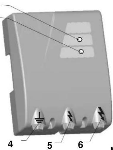 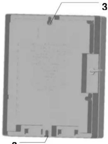 Mains plug is used as ON / OFF!Connection to 230 V ~!This energizer shall not be used as an animal trainer (inside a barn). Mains plug is used as ON / OFF!Connection to 230 V ~!This energizer shall not be used as an animal trainer (inside a barn). | 1 | Indicator light fence |
| 2 | Indicator light earth | |
| 3 | Fastening holes | |
| 4 | Earth connection | |
| 5 | Fence connection with reduced energy | |
| 6 | Fence connection with maximum energy |
a.) Installation
Fastening holes (4) are provided for wall mounting. The unit must be mounted against a vertical, fireproof wall with the connections at the bottom, see above picture, left part. For outside installation the device must also be protected against exposure to rain and direct sunlight.
b.) Functional description of the appliance
Commission device WITHOUT fence and connection to earth. The control lights flash in time to the impulses (green or red). The device is ready for operation. If control lights do not flash, the power supply or power supply line must be checked first. If no fault can be detected, the device should be tested by a specialist.
c.) Functional description with CONNECTED fence system (earthing + fence)
| 1 | Control light fence (1) | Flashing green: | State of fence ok = output voltage >3500V = minimum requirement |
| Flashing red: | State of fence faulty = output voltage ≤ 3500V, see operating instructions enclosed, possible sources of error (fig. 2, pg.5) | ||
| 2 | Control light earth (2) | Flashing green: | State of connection to earth ok; earth voltage < 1000 V |
| Flashing red: | State of connection to earth faulty, earth voltage ≥ 1000 V, see operating instructions enclosed, possible sources of error (fig. 2, pg.5) and connection to earth (pg.4) |
Connection variants:
Fence system closed:
Fence system open:
Fence systems may be operated independent of each other at the fence connections (5 or 6).
The measured value indicated in the display (1) and the associated indicator light are nevertheless only capable of displaying the exit exactly with maximum energy (6). If the indicator light flashes faster than once per second, the appliance must be disconnected at once and checked by a technician before it can be used again.
New function in accordance with EN 60335-2-76
Following a delay time of 15 seconds this device delivers an output energy of no more than 5 joules.
With an increasing load the device increases its output energy after a delay time has lapsed and therefore automatically adjusts the shock strength to the increased growth, weather conditions and fence status.
Any user of electric fence systems is legally indebted to control the fence-appliance and the fence system regularly, in accordance with the conditions of use, at least once per day.
- visual check of the appliance and the fence system
measurement of the minimum voltage of 2500V at each point of the fence
This equipment carries a 3-year warranty in accordance with our Warranty Terms & Conditions!
Please see the attached Operating Instructions for safety tips, earthing, commissioning, warranty terms and conditions and potential sources of fault!
Operating Instructions
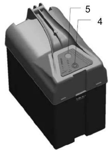
A 400
| 1 | Fence voltage Indicator light | OK |
| 2 | 12V-ACCUMULATOR indicator light | CHECK |
| 3 | 2-step switch | |
| 4 | Socket for solar / mains adapter + protective cover | |
| 5 | 12V battery connection cable | |
| 6 | Earth connection | |
| 7 | Fence connection | |
| 8 | Fastening holes | |
a.) Installation
The unit must, as a rule, be installed vertically with the connections at the bottom and, if possible, protected against rain, see above picture, left side. In case of wall mounting, it must be mounted against a fireproof wall. For outdoor installation, a zinc-plated metal casing can be used. This accessory (part No. 44656) protects the unit and also accommodates the accumulator.
b.) Functional description of the unit
Put unit into service WITHOUT fence and earthing. When connecting the 12V accumulator, be sure to observe the correct polarities (red + and black -). If the fence light (1) flashes green, the unit is ready for use. If in addition the accumulator light (2) flashes red, check the 12V accumulator for correct voltage. If the fence light (1) does not flash, check the polarity of the 12V connecting cable on the accumulator or have the unit checked by a technician. When operating the unit with solar module or mains adapter, first remove the protective cover (4).
Switch positions: 0 = OFF;
$$ I = \text { reduced current consumption and output power } \quad (= 50 \%) $$
$$ \text { Il } = \text { maximum output power and current consumption } \quad (= 100 \%) $$
c.) Functional description with connected fence system ( fence + earth )
| Accumulator light (2) flashes red | Fence light (1) flashes green | Audible clicks | Output voltage 12V accumulator | ||
| 1 | NO | YES | YES | OK OK | |
| 2 | NO | NO | YES | see fault finding in the enclosed instruction manual (Figure 2, p.5)! | OK |
| 3 | YES | YES | YES | OK | Charge or replace as soon as possible |
| 4 | YES | NO | YES | see fault finding in the enclosed instruction manual (Figure 2, p.5)! and: | Charge or replace as soon as possible |
| 5 | YES | NO | NO | No pulses, deep charge protection activated | Charge or replace at once |
| 6 | NO | NO | NO | See b.) Functional description of the appliance, without fence and earth | |
If the fence light (1) flashes faster than approx. once per second, the unit must be disconnected at once and checked by a technician before it can be used again.
For increased running time, a number of Solar modules with support stands can be used. We recommend the use of a wet accumulator at 12V-85Ah or 12V-110Ah. The accessories for this unit are obtainable through specialized dealers! Mains adapter = Art.-Nr. 371012
!!!Attention: Earth electrodes are not included in the supply (use at least 3 earth electrodes approx_1m long) !!!
Any user of electric fence systems is legally indebted to control the fence-appliance and the fence system regularly, in accordance with the conditions of use, at least once per day.
visual check of the appliance and the fence system
measurement of the minimum voltage of 2500V at each point of the fence
This equipment carries a 3-year warranty in accordance with our Warranty Terms & Conditions!
Please see the attached Operating Instructions for safety tips, earthing, commissioning, maintenance of battery and accumulator, warranty terms and conditions and potential sources of fault!
Operating Instructions
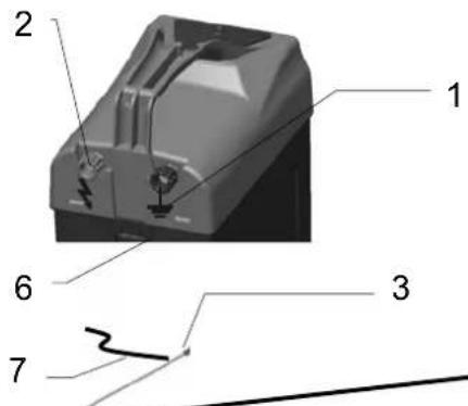
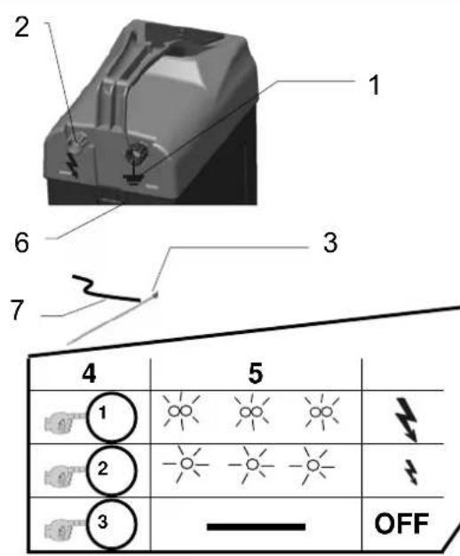
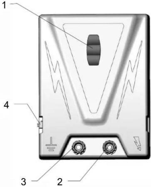
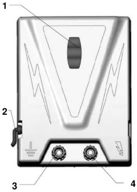
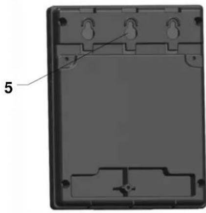
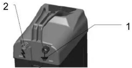
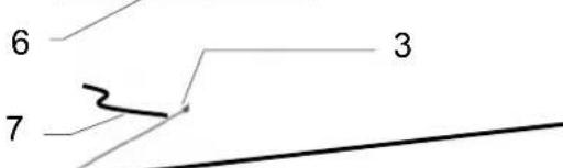
B 17
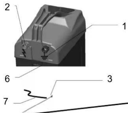
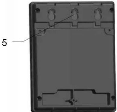
| 4 | 5 | |
| 1 | ||
| 2 | ||
| 3 | OFF |
Normal operation with 9V dry battery; alternatively, the appliance can be operated with a 12V wet accumulator! This energizer shall not be used as an animal trainer (inside a barn).
| 1 | Earth connection |
| 2 | Fence connection |
| 3 | Earth electrode |
| 4 | ON / OFF switch |
| 5 | Indicator light |
| 6 | Drilled hole for 12V cable |
a.) Installation
Assemble the earth electrode (3) as shown in the above figure; screw the earth connecting cable (7) onto the earth electrode with the fastening screw. Drive the earth electrode into the ground as far as the angle brackets and then place the appliance in upright position in the screwed-on angle brackets, see above figure.
b.) Functional description of the device
- The device is opened by pressing both sides of the cover while simultaneously pulling up.
- Place the battery in the case and connect the device. Close the cover.
(Only operate the device in the upright position and with the cover firmly latched)
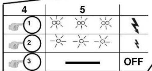
Commissioning the device without connection of the fence system:
- Switch on the device by pressing the button [4]
- If the control lamp [5] blinks (twice) in an interval of approx. 1.3 sec., the device is functional and in EXTREME mode (high shock strength with higher current consumption).
- If the button [4] is pressed for a second time, the device switches to ECO mode with lower output and current consumption. This is displayed by single blinking at an interval of approx. 1.3 sec.
- If the button [4] is pressed for a third time, the device is switched off. (no blinking)
Hint:
If the control lamp [5] does not blink or blinks red after switching on, the battery must be checked for correct polarity and a minimum voltage of approx. 6V or the device must be inspected by a specialty technician!
c.) Functional description with connected fence system (fence + earthing)
If the control lamp [5] blinks red (battery voltage less than 6V), the battery must be replaced.
The control lamp [5] only serves as a functional check and does not react to faults in the fence system or outage of fence voltage.
Therefore, periodic checking of the voltage (>2.5 kV) on the fence is essential.
The device provides 12v operation with total discharge protection. This is indicated by red blinking of the pilot lamp. If the control lamp [5] should blink faster than 1x per second, the device must be switched off immediately and inspected by a specialty technician before re-commissioning.
Any user of electric fence systems is legally indebted to control the fence-appliance and the fence system regularly, in accordance with the conditions of use, at least once per day.
- visual check of the appliance and the fence system
- measurement of the minimum voltage of 2500V at each point of the fence
This equipment carries a 3-year warranty in accordance with our Warranty Terms & Conditions! Please see the attached Operating Instructions for safety tips, earthing, commissioning, maintenance of battery and accumulator, warranty terms and conditions and potential sources of fault!
| 4 | 5 | |
| OFF |