Super Brute SB3555 - Pressure washer Simpson - Free user manual and instructions
Find the device manual for free Super Brute SB3555 Simpson in PDF.
| Product Type | Gas Pressure Washer |
| Brand | Simpson |
| Model | Super Brute SB3555 |
| Engine | 4-stroke gas, electric and recoil start |
| Maximum Pressure | 3500 PSI (241 bar) |
| Maximum Flow Rate | 2.5 GPM (9.5 L/min) |
| Pump Type | Triplex brass pump |
| Power Supply | None (gas engine) |
| Recommended Fuel | Unleaded gasoline, 87 octane, max 10% ethanol |
| Fuel Tank Capacity | 1 gallon (3.8 L) |
| Dimensions (L x W x H) | 48 x 32 x 36 inches (122 x 81 x 91 cm) |
| Weight | 150 lb (68 kg) |
| High Pressure Hose Length | 50 feet (15.2 m) |
| Included Nozzles | 5 colored nozzles: 0° (red), 15° (yellow), 25° (green), 40° (white), soap (black) |
| Detergent Injection System | Yes, siphon with soap nozzle |
| Safety Features | Low oil shutdown, thermal relief valve, trigger lock, ground fault circuit interrupter (GFCI) |
| Routine Maintenance | Engine and pump oil change, air and fuel filter cleaning, pump purge |
| Pump Warranty | 5 years parts, 1 year labor |
| Frame Warranty | 10 years parts, 1 year labor |
Frequently Asked Questions - Super Brute SB3555 Simpson
User questions about Super Brute SB3555 Simpson
0 question about this device. Answer the ones you know or ask your own.
Ask a new question about this device
Download the instructions for your Pressure washer in PDF format for free! Find your manual Super Brute SB3555 - Simpson and take your electronic device back in hand. On this page are published all the documents necessary for the use of your device. Super Brute SB3555 by Simpson.
USER MANUAL Super Brute SB3555 Simpson
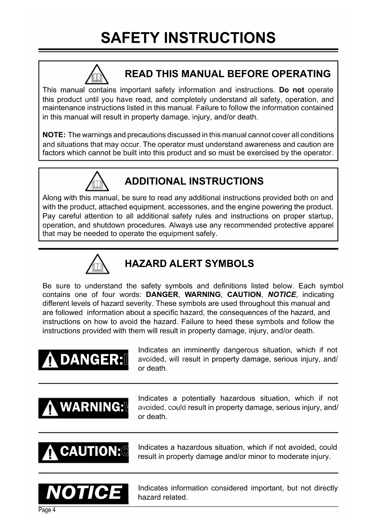
natural_image
Line drawing of a portable industrial machine with wheels and control panel (no text or symbols)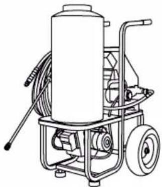
natural_image
Line drawing of a mechanical pressure pump with hoses and wheels (no text or symbols)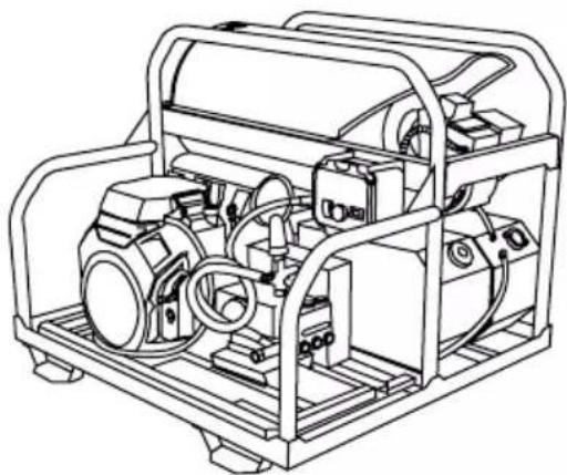
natural_image
Technical line drawing of a mechanical device with internal components (no text or symbols)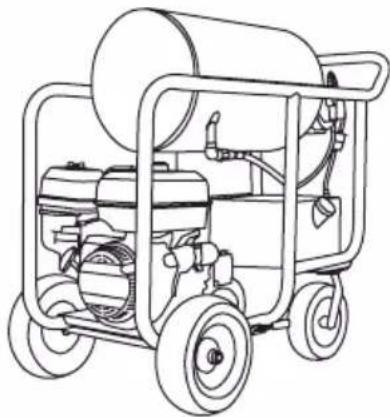
natural_image
Line drawing of a portable water purifier with wheels and equipment (no text or symbols)
LOOK BEFORE YOU PUMP!

READ THIS MANUAL CAREFULLY BEFORE OPERATION
Failure to follow the instructions and safety precautions in this manual can result in property damage, serious injury and/or death.
If your pressure washer is not working or if there are parts missing or broken, please DO NOT RETURN IT TO THE PLACE OF PURCHASE. Contact our Customer Service Department by calling 1-877-362-4271 or emailing cservice@fna-group.com
SAVE THIS MANUAL FOR FUTURE REFERENCE
NOTE: Photographs and line drawings used in this manual are for reference only and may not represent your specific model.
THIS PAGE WAS INTENTIONALLY LEFT BLANK
SAVE THIS MANUAL FOR FUTURE USE
Keep this manual for future reference. This manual should be considered a permanent part of the product and stay with it. This manual should be available to anyone operating the product(s) it covers. This manual should remain with the product(s) it covers if sold to a new owner. If the manual becomes damaged, lost, or otherwise unusable, you may download a new copy from the product pages at www.simpsoncleaning.com or contact customer support by calling 1-877-362-4271.
Write down the model number, serial number, and purchase date of this product in the spaces provided below then keep this manual with the purchase receipt(s) for future reference.
Model Number:
Serial Number:
Purchase Date:
TABLE OF CONTENTS
| 4SAFETY INSTRUCTI | |
| Read this Manual Before Operating | 4 |
| Additional Instructions | 4 |
| Hazard Alert Symbols | 4 |
| 6DISCLAIMERS | |
| 6PERSONAL PROTEC | |
| 7IMPORTANT SAFETY | |
| Gasoline or Diesel Driven | 7 |
| Electric Driven | 14 |
| 16GET TO KNOW THE | |
| Pressure Washer Terminology | 16 |
| 18ASSEMBLY | |
| Assemble the Spray Gun | 18 |
| Organize Accessories | 18 |
| Adding the Pump Breather Cap | 19 |
| 19CONNECTING HOS | |
| PRESSURE WASHER OPERATING FEATURES | 20 |
| Pressure Adjustments | 20 |
| How to use the Spray Wand | 21 |
| Changing Nozzles on the Spray Wand | 21 |
| 22COMPONENT LOCA | |
| Engine Powered Pressure Washer | 22 |
| Engine Powered, Skid Mounted Pressure Washer | 23 |
| Electric Powered Pressure Washer | 24 |
| 26HOW TO APPLY CL | |
| 27ENGINE PREPARA | |
| Gasoline Engine Oil | 27 |
| Gasoline Engine Fuel | 28 |
| Diesel Engine Oil | 30 |
| Diesel Engine Fuel | 31 |
| BATTERY CONNECTIONS | 31 |
| PURGING AIR FROM THE PUMP | 32 |
| OPERATING CHECKLIST | 33 |
| Location | 33 |
| High Altitude Operation | 34 |
| Operating Conditions | 34 |
| 36STARTING THE EN | |
| Gasoline Engine - Electric Start | 36 |
| Gasoline Engine - Recoil Start | 36 |
| Starting the Engine - Diesel | 37 |
| STARTING ELECTRIC PRESSURE WASHER | 38 |
| 40HOT WATER OPER | |
| Filling the Burner Fuel Tank | 40 |
| Starting the Burner | 40 |
| 41SHUTTING DOWN | |
| 42OPERATION TIPS | |
| Preparation | 42 |
| Pressure Washing | 42 |
| 42HOUR METER | |
| 43MAINTENANCE | |
| Cleaning the Pressure Washer | 43 |
| Pework Inspection | 43 |
| Connections | 43 |
| Nozzle Cleaning | 44 |
| Water Inlet Filter | 44 |
| Engine Maintenance | 45 |
| Pump Maintenance | 45 |
| Maintenance Schedule Chart | 46 |
| 47STORAGE AND TR | |
| Storing for Two Months or Less (Gasoline) | 47 |
| Storing for Two Months or less (Diesel) | 47 |
| Storing for Two Months or Less (Electric Powered) | 47 |
| Storing for Two Months or More (Gasoline) | 48 |
| Storing for Two Months or More (Diesel) | 48 |
| Storing for Two Months or More (Electric Powered) | 48 |
| Transportation | 49 |
| ® PUMP GUARD | 50USING SIMPSON |
| 51TROUBLESHOOTIN | |
| Power System: Gasoline or Diesel Driven | 51 |
| Power System: Electric Driven | 52 |
| Pumping System | 52 |
| Heating Burner System: Diesel Fired | 54 |
| Heating Burner System: Natural Gas or Liquid Propane Fired | 56 |
| 59LIMITED WARRAN' |
READ THIS MANUAL BEFORE OPERATING
This manual contains important safety information and instructions. Do not operate this product until you have read, and completely understand all safety, operation, and maintenance instructions listed in this manual. Failure to follow the information contained in this manual will result in property damage, injury, and/or death.
NOTE: The warnings and precautions discussed in this manual cannot cover all conditions and situations that may occur. The operator must understand awareness and caution are factors which cannot be built into this product and so must be exercised by the operator.
ADDITIONAL INSTRUCTIONS
Along with this manual, be sure to read any additional instructions provided both on and with the product, attached equipment, accessories, and the engine powering the product. Pay careful attention to all additional safety rules and instructions on proper startup, operation, and shutdown procedures. Always use any recommended protective apparel that may be needed to operate the equipment safely.
HAZARD ALERT SYMBOLS
Be sure to understand the safety symbols and definitions listed below. Each symbol contains one of four words: DANGER, WARNING, CAUTION, NOTICE, indicating different levels of hazard severity. These symbols are used throughout this manual and are followed information about a specific hazard, the consequences of the hazard, and instructions on how to avoid the hazard. Failure to heed these symbols and follow the instructions provided with them will result in property damage, injury, and/or death.

text_image
DANGER:Indicates an imminently dangerous situation, which if not avoided, will result in property damage, serious injury, and/or death.

Indicates a potentially hazardous situation, which if not avoided, could result in property damage, serious injury, and/or death.

Indicates a hazardous situation, which if not avoided, could result in property damage and/or minor to moderate injury.

Indicates information considered important, but not directly hazard related.
CAUTION

text_image
TRIPPING HAZARDHoses may pose a tripping hazard that can cause injuries resulting from a fall.

SLIP / TRIP HAZARDS
When pressure washing in public areas, signs should be posted that indicate to stay clear of the area as high-pressure washing is being performed. Also, signs should be posted that the surface may be slippery and trip hazards may be present.
Special consideration needs to be made to the safety of not just the operator of the pressure washer, but also people who may be adjacent to the area being cleaned. The best way to warn unsuspecting individuals is with signage and barriers.
Barriers can be as simple as plastic traffic cones or barricades to using barrier belts around the area being cleaned. Remember, pressure washing can dislodge weak or broken pavement turning it into projectiles that may injure others. Keeping people clear of the area is the best way to avoid injury.
Wet pavement can be slippery to unsuspecting individuals causing injury from slips and falls. High-pressure and low-pressure hoses can be trip hazards. Segregating the area and placing appropriate signage can reduce injury.
Sign examples

text_image
CAUTION Watch your step
text_image
CAUTION Slippery when wet.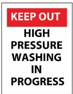
text_image
KEEP OUT HIGH PRESSURE WASHING IN PROGRESS
text_image
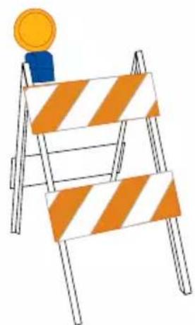
CAUTION SLIPPERY WHEN WETBarrier examples

natural_image
Illustration of a construction barrier with orange and white stripes, topped by a yellow coin (no text or symbols)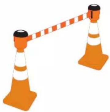
natural_image
Illustration of two orange traffic cones with white and orange stripes, connected by a diagonal bar (no text or symbols)
CALIFORNIA PROPOSITION 65 WARNING
This product and the engine exhaust can expose you to chemicals which are known to the state of California to cause cancer, birth defects, or other reproductive harm. For more information on California Proposition 65, go to www.P65Warnings.ca.gov.

POLYCYCLIC AROMATIC HYDROCARBON WARNING
The air filter element and air box assembly may contain polycyclic aromatic hydrocarbons (PAHs). Some PAHs may cause cancer. To avoid exposure to PAHs, wear gloves when performing air filter maintenance.

SPARK ARRESTING MUFFLER
This product may not be equipped with a spark-arresting muffler. If the product is NOT equipped and to be used around flammable materials or on land covered with materials such as agricultural crops, forest, brush, grass or other similar material, then a spark arrester MUST be installed and is legally required in the state of California.
It is a violation of California statutes section 130050 and/or sections 4442 and 4443 of the California Public Resource Code, unless the engine is equipped with a spark arrester, as defined in section 4442, and maintained in effective working order.
Spark arresters are also required on some U.S. Forest Service land and may also be legally required under other statutes and ordinances.
DISCLAIMERS

All information in this publication was based on the latest product information available at the time of printing. The FNA Group reserves the right to update, change, and/or improve the product and this document at any time, without notice and without incurring any obligation.
This manual may cover more than one machine. The pictures and figures in the manual should be used for reference only. There may be differences between your product and the pictures, drawings and diagrams in this manual.
If you loan, rent or sell this machine, be sure to include all instructional materials with the unit!
PERSONAL PROTECTIVE EQUIPMENT (PPE)
It is important to understand what personal protective equipment (PPE) should be utilized when using your pressure washer. Below is a list of PPE items that should be utilized at all times when using the pressure washer.
Hearing - Ear plugs or muffs to protect your hearing.
Vision - Safety glasses or goggles to protect your eyes.
Clothing - Long pants to protected your legs from flying debris.
Shoes - Shoes that fully cover your feet to protect against debris and over spray.


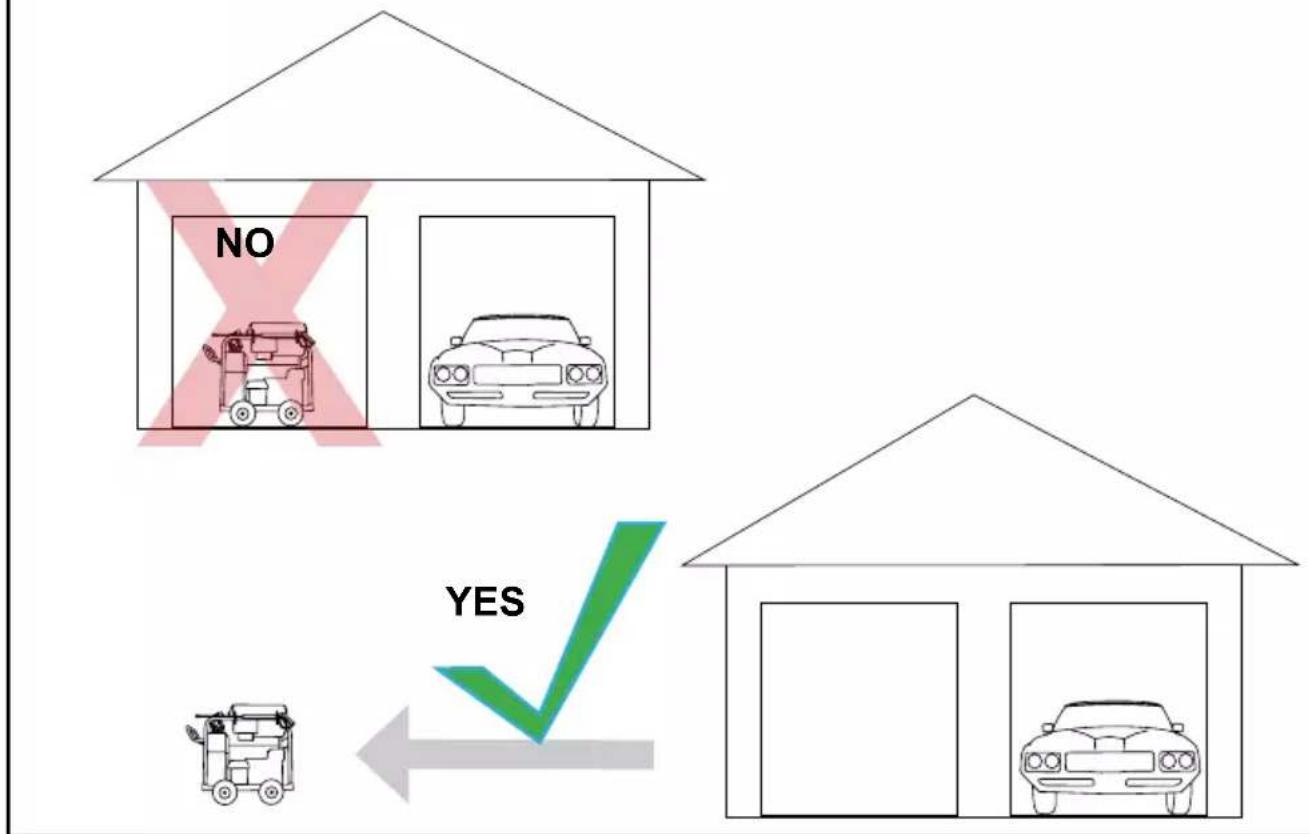
TOXIC FUMES
Engine exhaust contains carbon monoxide, an odorless, colorless, poisonous gas. Running an engine indoors will kill you in minutes. Never use this product inside a house, garage, or any other kind of enclosure even if doors and windows are open. Run engine outside at least 20 feet (6 meters) away from windows, doors, and vents. Carefully consider wind direction and air currents when using this product outside to avoid breathing in engine exhaust. Always use a carbon monoxide detector in any occupied buildings near the running engine.
NEVER use an engine or oil burner inside homes, garages, crawlspaces or other partly enclosed areas. Deadly levels of carbon monoxide can build up in these areas. Using a fan or opening windows and doors does NOT supply enough fresh air.
ONLY use outdoors and far away from open windows, doors or vents. These openings can pull in engine or burner exhaust. Never operate the pressure washer in or near a location occupied by humans or animals.
Even when the engine is used correctly, carbon monoxide may leak into your home. ALWAYS use a battery-powered or battery backup carbon monoxide detector in your home. Read, follow and understand all directions for the carbon monoxide detector before using it or this pressure washer. If you feel sick, dizzy or weak at anytime, move to fresh air immediately then seek the care of a physician. You could have carbon monoxide poisoning!

Do not operate this unit until you have read this instruction manual and the engine instruction manual for safety, operation and maintenance instructions. If you have any questions regarding this product, please contact our customer service at 1-877-362-4271 or email at: cservice@fna-group.com
SAVE THIS MANUAL FOR FUTURE USE

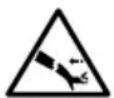
INJECTION INJURY
Risk of injection or severe injury. Keep clear of the nozzle. DO NOT direct the stream at persons, pets or animals. DO NOT use a leaking high-pressure hose. DO NOT attempt to repair the high-pressure hose, REPLACE IT!
| WHAT CAN HAPPEN HOW TO PREVENT IT | |
| Spilled fuel (gasoline, diesel, kerosene, approved alternative fuels) and it's vapors can become ignited from cigarette sparks, electrical arcing, exhaust gases and hot engine components such as the muffler. | Shut off the engine and allow it to cool before adding fuel to the tank(s).During refueling, all ignition sources and switches should be in the OFF position.Use care in filling tank to avoid spilling fuel. Move pressure washer away from the fueling area before starting engine. |
| Heat will expand fuel in the tank which could result in spillage and possible fire or explosion. | Keep maximum fuel level 1/2" (12.7mm) below bottom of filler neck to allow for expansion. |
| Operating the pressure washer in an explosive environment could result in a fire. | Operate and fuel equipment in well ventilated areas free from obstructions.Keep a fire extinguisher rated for gasoline fires within reach. |
| Materials placed against or near the pressure washer can interfere with its proper ventilation features causing overheating and possible ignition of the materials. | Never operate pressure washer in an area containing dry brush or weeds. |
| Improperly stored fuel could lead to accidental ignition. Fuel improperly secured could get into the hands of children or other unqualified persons. | Store engine and burner fuel in a clean OSHA approved container, in a secured location away from the work area. Do not allow debris or moisture into the container. |
| Spraying gasoline, kerosene or any kind of flammable solvent with this product could result in serious injury or DEATH. | Do not spray flammable liquids. |
| Flammable liquids can create fumes which can ignite causing property damage or serious injury. | Only fuel in a well ventilated area. Clean up any spills promptly and do not start the engine in the same area where you filled the tanks. |
WHAT CAN HAPPEN HOW TO PREVENT IT
| Breathing exhaust fumes will cause serious injury or DEATH! Engine exhaust contains carbon monoxide, an odorless, colorless gas. | Only operate pressure washer in a well ventilated area. DO NOT use in enclosed areas like a garage, basement, etc.Never operate unit in or near a location occupied by humans or animals.Never connect pressure washer to a TYPE B gas vent. |
| Some cleaning fluids contain substances which could cause injury to skin, eyes or lungs. | Use only cleaning fluids specifically recommended for pressure washers. Follow manufacturers recommendations. DO NOT use chlorine bleach or any other corrosive compound. |

RISK OF FLUID INJECTION AND LACERATION
WHAT CAN HAPPEN HOW TO PREVENT IT
| Your pressure washer operates at fluid pressure and velocities high enough to penetrate human and animal flesh which could result in amputation or other serious injury. Leaks caused by loose fittings or worn or damaged hoses can result in injection injuries. DO NOT TREAT FLUID INJECTION AS A SIMPLE CUT! See a physician immediately. | Inspect the high-pressure hose regularly, Replace the hose immediately if it is damaged, worn, has melted from contacting the engine or show signs of cracks, bubbles, pinholes, or other leakage. NEVER grasp a high-pressure hose that is leaking or damaged.Never touch a high-pressure hose with a pinhole or similar leak. The steam of water is under high pressure and WILL penetrate skin.Never place hands in front of the nozzle.Direct the spray away from self or others.Make sure the hose is in good condition and the connections are tight.Do not allow hose to contact the muffler.Never attach or remove wand or hose while system is pressurized.Use only accessories rated equal to or higher than the rating of the pressure washer. |
| Injures can result if system pressure is not reduced before attempting maintenance or disassembly. | To relieve system pressure: shut off engine, turn off water supply and pull gun trigger until water flow stops. |
| WHAT CAN HAPPEN | HOW TO PREVENT IT |
| High velocity fluid can cause objects to break, projecting particles at high speed. | Always wear safety glasses. Wear protective clothing to protect against accidental spraying.Never point wand at or spray people and/or animals. |
| Light or unsecured objects can become hazardous projectiles. | Always secure trigger lock when wand is not in use to prevent accidental spraying.Never permanently secure trigger in pullback (open) position. |

| WHAT CAN HAPPEN | HOW TO PREVENT IT |
| Unsafe operation of your pressure washer could lead to serious injury or death to you or others. | Do not use chlorine bleach or any other corrosive compound.Become familiar with the operation and controls of the pressure washer.Keep operating area clear of all persons, pets and obstacles.Do not operate the unit when fatigued or under the influence of drugs and/or alcohol. Stay alert at all times.Never compromise the safety features of the pressure washer.Do not operate the machine with missing, broken or unauthorized parts.Never leave the machine unattended while running. Turn the machine off.Do not obstruct the burner exhaust.Never tamper with the thermal relief valve.Do not tamper with the unloader valve.Do not modify the pressure washer in any way.Never attempt to repair a damaged high-pressure hose. Replace it. |
| If the proper starting procedure is not followed, engine can kickback causing serious hand and arm injuries. | Pull starter cord slowly until resistance is felt, then pull cord rapidly to avoid kickback and prevent hand or arm injury. If the engine does not start after two attempts, squeeze the trigger to release pump pressure. |
| The spray gun/wand is a powerful cleaning tool that could look like a toy to a child. | Keep children away from the pressure washer at all times.Never leave the pressure washer unattended while running.Always relieve pressure from the system once you have stopped the engine. |
| Reactive force of the spray will cause gun/wand to kickback and could cause the operator to slip or fall or misdirect the spray. Improper control of the gun/wand can result in injuries to self or others. | Do not overreach or stand on an unstable support.Do not use pressure washer while standing on a ladder.Grip gun/wand firmly with both hands. Expect gun to kickback when triggered. |

RISK OF INJURY OR PROPERTY DAMAGE WHEN TRANSPORTING OR STORING
| WHAT CAN HAPPEN | HOW TO PREVENT IT |
| Fuel or oil can leak or spill and could result in a fire or breathing hazard.Serious injury or death can result. Fuel or oil leaks will damage carpet, paint or other surfaces in a vehicle or trailer.Oil could fill the compression cylinder and damage the engine if the unit is not stored or transported in an upright position. | If pressure washer is equipped with a fuel shut-off valve, turn the valve to the OFF position before transporting to avoid fuel leaks. If the pressure washer is not equipped with a fuel shut-off valve, drain the fuel from the tank before transporting.Only transport fuel in an OSHA-approved container.Always place pressure washer on a protective mat when transporting to protect against damage to vehicle from leaks.Always transport and store unit in an upright position. Remove pressure washer from vehicle immediately upon arrival at your destination. |
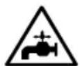
| Spray directed at electrical receptacles or switches, or objects connected to an electrical circuit, could result in a fatal electrical shock. | Direct spray away from electric receptacles, switches and equipment.Never clean any electrically operated device, even when disconnected, unless it clearly states in its manual that such cleaning is approved. |

RISK OF CHEMICAL BURN
WHAT CAN HAPPEN HOW TO PREVENT IT
Use of acids, toxic or corrosive chemicals, poisons, insecticides or any kind of flammable solvent with this pressure washer could result in serious injury or death.
Do not spray acids, gasoline, kerosene or any flammable materials with this product. Use only household detergents, cleaners and degreasers that are approved for use with pressure washers.
Wear goggles, shoes and protective clothing to protect eyes and skin from contact with the sprayed materials.


RISK OF BURSTING
WHAT CAN HAPPEN HOW TO PREVENT IT
High-velocity spray directed at pneumatic tire sidewalls (such as found on automobiles, trailers and the like) could damage the sidewall resulting in serious injury.
On pressure washers rated above 1600 psi (11032 kPa) use the widest fan spray (40° nozzle) and keep the spray a minimum of 8" (20cm) from the pneumatic tire sidewall. Do not aim spray directly at the joint between the tire and rim.
| WHAT CAN HAPPEN | HOW TO PREVENT IT |
| Contact with hot surfaces, such as engine exhaust components, could result in serious burns. | During operation, touch only the control surfaces of the pressure washer. Keep children away from the pressure washer at all times. They may not be able to recognize the hazards of this product. |
| Contact with spray will result in a serious burns. | DO NOT touch spray! ALWAYS direct spray away from self and others. |

RISK OF INJURY FROM LIFTING
| WHAT CAN HAPPEN | HOW TO PREVENT IT |
| Serious injury can result from attempting to lift too heavy of an object. | The pressure washer is too heavy to be lifted by one person. Obtain assistance from others before lifting. |

RISK OF PROPERTY DAMAGE
| WHAT CAN HAPPEN | HOW TO PREVENT IT |
| Muffler and burner exhaust heat can damage painted surfaces, melt any material sensitive to heat (such as siding, plastic, rubber, vinyl or the pressure hose, itself) and damage live plants. | Always keep pressure washer a minimum of 4 feet (1.2 meters) away from surfaces (such as houses, automobiles or live plants) that could be damaged from muffler exhaust heat. |
SAVE THESE INSTRUCTIONS FOR FUTURE USE

CALIFORNIA PROPOSITION 65 WARNING
This product can expose you to chemicals, including lead and lead compounds, which are known to the state of California to cause cancer, birth defects, or other reproductive harm. For more information on California Proposition 65, go to www.P65Warnings.ca.gov.

Please read the entire manual before attempting to assemble, operate or install this product.
This unit was designed for specific applications. It should not be modified and/or used for any application other than that which is was designed.
Always store the pressure washer in a location where the temperature will not fall below 40^ F ( 4^ c). Freeze damage is not covered by the warranty.
If you loan, rent or sell this machine, be sure to include all instructional materials with the unit!
SAVE AND READ THESE INSTRUCTIONS
When using this product, basic precautions should always be followed including the following:
- Do not touch plug or receptacle with wet hands
- Avoid accidental starts. Move switch on the unit to the OFF position before connecting or disconnecting cord from electrical receptacles.
- Water spray must never be directed towards any electric wiring or directly toward the pressure washer itself as fatal electrical shock may occur.
- Never carry or pull your pressure washer by the electrical cord. Do not pull or yank on the cord to disconnect it from the electrical receptacle.
- To prevent damage, the cord should not be crushed, placed next to sharp objects or near a heat source.
- Inspect the electrical power supply cord before connecting it to an electrical receptacle. Damaged cords can reduce performance or cause a fatal electrical shock.
- Disconnect power plug from the receptacle when not in use and prior to detaching the high-pressure hose.
- The pressure washer should not be used in areas where flammable vapors may be present. An electrical spark could cause an explosion or fire.
- To minimize water infiltration to the pressure washer motor, locate the pressure washer as far as possible from the cleaning site during operation.
- Allow free air circulation to the pressure washer. Never cover the pressure washer during operation or directly after being used.
- Never defect the safety devices on the pressure washer.
- Never use the pressure washer with an electrical extension cord. Move the pressure washer closer to the receptacle instead.
MOTOR OVERLOAD
This pressure washer is equipped with an overload protection device which will automatically shut off the motor in the event the motor draws excessive current or overheats.
GROUNDING INSTRUCTIONS
This product must be grounded. If it should malfunction or break down, grounding provides a path of least resistance for the electric current to reduce the risk of electric shock. This product is equipped with a power supply cord having an equipment grounding conductor and a grounded plug. The plug must be plugged into a properly installed and grounded receptacle that meets all local codes and ordinances. DO NOT use any type of grounding adapter.

WARNING:
ELECTRICAL GROUNDING
Improper connection of the equipment grounding conductor can result in the risk of electrocution. If in doubt of proper grounding, have a licensed electrician verify the installation of the receptacle. Do not modify the plug provided with the product if it will not fit the receptacle installed. Do not use any type of adapter with this product.
GROUND FAULT CIRCUIT INTERRUPTER (GFCI) - (IF EQUIPPED)
This pressure washer is provided with a Ground Fault Circuit Interrupter (GFCI) built into the plug of the power supply cord. This device provides additional protection from the risk of electrical shock. Should replacement of the plug or cord becomes necessary, use only identical replacement parts that included GFCI protection.
POWER SUPPLY AND ELECTRICAL INFORMATION
This cord should only be connected to an electrical outlet installed in accordance with local codes and ordinances.
A. Inspect cord before using. Do not use if the cord is damaged in any way.
B. Keep all connections dry and off of the ground.
C. Do not touch the plug with wet hands.
D. For a product rated 250 volts or less, single phase; this product is provided with a ground fault circuit interrupter built into the plug. If replacement of the plug or cord is necessary, use only identical replacement parts.
E. In the situation where the power supply is rated above 250 volts and/or is three phase, this product must be plugged into a receptacle protected by a ground fault circuit interrupter.
F. Read the instruction manual(s) before using this product.

text_image
WARNING: VTo reduce the risk of electrocution, keep all connections dry and off the ground. Do not touch the plug or power supply receptacle with wet hands!
12 volt DC Battery (if equipped): The 12 volt battery operates the engine's electrical starting system. After the engine is started, the system will charge the battery and operate the burner (if equipped). The 12 volt battery will need to be replaced regularly to ensure consistent performance.
Back Flow Preventer: Prevents back flow of water from the pressure washer into a potable water system.
BTU (British Thermal Unit): The amount of work or energy it takes to raise the temperature of one pound of water by one degree Fahrenheit.
Burner Assembly: A device used to change fuel into heat energy. It is used to heat the water in the coil assembly and is designed to use #2 diesel fuel or kerosene.
Bypass Mode: Allows water to recirculate within the pump when the gun trigger is not pulled. This feature allows the operator to release the trigger gun and reposition themselves without having to turn the engine off between cleaning actions.
NOTE: Never allow the unit to run in bypass mode for longer than two minutes.
Chemical Injection System (if equipped): Mixes cleaners or cleaning solvents with the water to improve cleaning effectiveness.
CU: Cleaning Units. GPM multiplied by PSI equals CU.
Diesel Engine (if equipped): An compression-ignition engine that uses diesel fuel to create rotational force for mechanical work.
EVAP canister (if equipped): A device that collects fuel vapors and later purges them so they burn in the combustion process.
Flow switch: A switch which responds to changes in water flow. The flow of water moves a magnet that operates a reed or micro switch. The switch controls voltage to the fuel solenoid in the burner system.
Gasoline Engine (if equipped): An internal combustion engine that uses gasoline as fuel to create rotational force for mechanical work.
GPM: Gallons Per Minute. The unit of measurement for the flow of water.
Spray gun: The device that is held to control the direction and flow of high-pressure water.
High-pressure Hose: A plastic or rubber hose that is constructed to withstand the high pressure output of a pressure washer. Never repair a high-pressure hose, always replace the damaged hose with one that is rated the same or higher pressure and within the temperature range of your pressure washer.
High Pressure Pump Oil: A lubricant that is specifically designed for use inside a high-pressure water pump. The preferred oil is SIMPSON® Premium Pump Crankcase Oil. If this oil is not available, SAE 15W-40 oil may be used. Refer to the section on Pump Maintenance in this manual as to the service intervals for your pump.
Hour Meter (if equipped): An analog or digital display timing device that records how many hours the pressure washer engine has ran in its lifetime. Use this information for preventative maintenance service intervals.
Nozzle: A device for the metering of fluids. The size and machining of the orifice determines the spray pattern as well as the rate of flow for a given pressure.
Pressure Relief Valve: A protective mechanical device that opens to atmosphere when the system pressure exceeds a preset level. NEVER tamper with or modify the pressure relief valve in anyway. SERIOUS INJURY or DEATH may result.
Pressure Switch: An electrical switch that activates at preset pressure levels through the function of a diaphragm. The pressure switch is used to control the fuel solenoid in the burner system.
Pressure Wand Assembly: The collection of parts that includes the gun, wand and nozzle.
PSI: Pounds per Square Inch. The unit of measurement for fluid or gas pressure. Exceeding the maximum operating pressure could result in damage to the unit, SERIOUS INJURY or DEATH.
Pump: Mechanical device that accelerates the movement of water through the pressure washer system. The pressure is created by the restrictive flow of the nozzle.
Temperature Control: A device that controls the temperature of the water. The adjustable temperature control (if equipped) allows the operator to tailor the temperature to the cleaning requirements. Never set the control above 195^ F. The burner will automatically shut off if insufficient water flow through the burner coil causes the temperature to rise above the setting.
Temperature Relief Valve (TRV): A protective device that opens to atmosphere should the temperature rise above a preset level. The TRV is typically located on the output side of the pump. Should the water temperature rise too high due to recirculation, the valve will open allowing cooler water to enter the pump. The valve will then close.
Unloader Valve: A mechanical device that adjusts itself due to the rate and pressure of fluid flowing through it. In a pressure washer, the unloader valve reroutes water through the pump when the gun trigger is released. This allows the water to circulate through the pump without undo pressure building. The unloader valve can be used as a pressure regulating device in certain situations.
Water Column (if equipped): A measurement of NG or LP gas pressure by the displacement of water within the manometer measuring device.
Water Supply: The source of water for the pressure washer. Typically the minimum requirement is twice the rated volume for the machine at 20 PSI.
Wand: Also known as a lance, is the extension piece from the gun to the quick connector for the nozzle.
Follow the steps outlined in this section assemble your pressure washer. If you have any questions regarding the assembly of your pressure washer, please have your model number and serial number ready, then contact customer support at 1-877-362-4271 or email cservice@fna-group.com.


INJECTION INJURY
The high pressures created by a pressure washer can cause fluid injection injuries, severe lacerations, amputations, and / or death. To avoid these hazards, always aim the spray gun and lance in a safe direction when using the pressure washer and never attempt to touch a leak in a high-pressure hose or fitting.
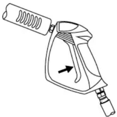
ASSEMBLE THE SPRAY GUN
Hand thread the lance clockwise into the gun. Be careful not to cross-thread the gun and lance. Using an adjustable wrench, tighten the lance by placing the wrench on the flats of the nozzle quick-connector.
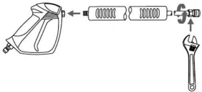
text_image
Diagram showing the assembly of a spray gun with spring-loaded components and an adjustable wrench, illustrating mechanical assembly steps.WARNING! The threads on the lance and gun coupler can be easily cross threaded resulting in an improper assembly. An improper assembly of the gun and lance can result in personal injury. Do not use if the threads on the gun coupler and or lance are cross threaded.
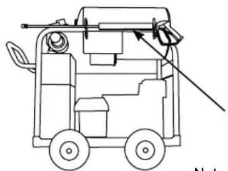
ORGANIZE ACCESSORIES
-
Place the spray gun and lance on the holders
-
Push the nozzles into the rubber grommet holders.
natural_image
Line drawing of a mechanical device with wheels and a tool, no text or symbols present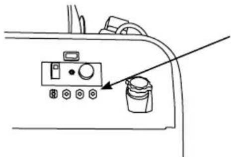
natural_image
Line drawing of a device panel with buttons and a paint bucket, no text or symbols presentNote: The unit shown above is used as an example. Your unit may vary in look and accessory placement.
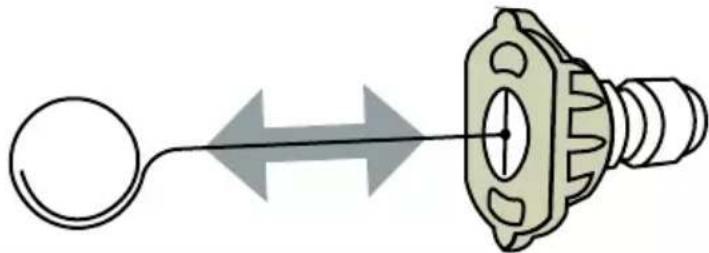
ADDING THE PUMP BREATHER CAP (if applicable)
The RED shipping plug, on the top of the pump, must be replaced with a BLACK breather cap. The cap is easy to replace with the following steps:
- Using a bladed screw driver, remove the RED shipping plug from the top of the pump.
- Hand thread the BLACK breather cap into the pump.
- Snug the cap with your fingers.
RED shipping plug
natural_image
Technical line drawing of a mechanical component with a diagonal line indicating direction (no text or symbols)
text_image
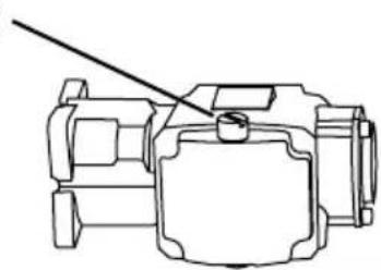
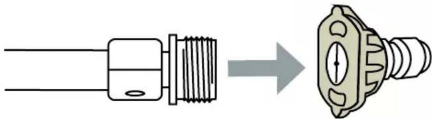
BLACK breather capCONNECTING HOSES
Before connecting a water supply hose, be sure the water supply is capable of providing an uninterrupted source of clean, cold water at a minimum rate of 5 gallons per minute (GPM) and 20 pounds per square inch (PSI) of pressure. Once a proper water supply is secured, follow the instructions below to connect both the water supply and high-pressure hoses to the pressure washer.
- Verify the inlet screen is free of any dirt or debris and is in place with the convex side facing out.
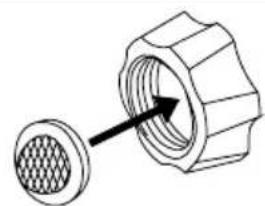
natural_image
Diagram of a mechanical component with a meshed circular base and a hexagonal nut, showing an arrow pointing to the internal structure (no text or symbols present)- Turn on the water supply and run for 30 seconds to purge any debris from the supply hose. Then, turn off the water supply and thread the water supply hose into the pump inlet.
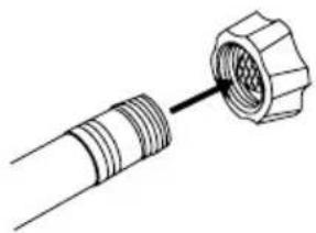
natural_image
Technical line drawing of a connector with threaded ends and a hexagonal nut (no text or symbols)- While pulling back on the pump outlet collar, insert the hose connector then release the collar. Gently tug on the hose to make sure it is locked.
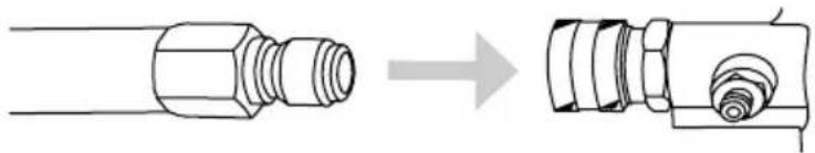
natural_image
Diagram showing a pipe fitting being processed from a cylindrical component to a mechanical component (no text or symbols present)- Thread the high-pressure hose into the gun.
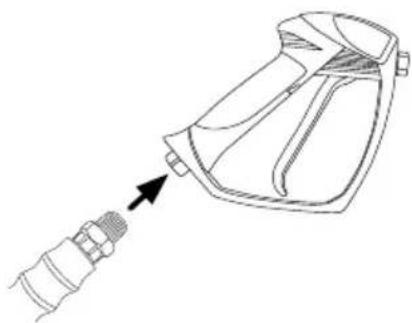
natural_image
Line drawing of a mechanical device with a connector inserted, showing no text or symbolsIMPORTANT! Become familiar with these features before operating the pressure washer.
PRESSURE ADJUSTMENTS (if applicable)
The pressure setting is preset at the factory to achieve optimum pressure and cleaning. If you need to lower the pressure, it can be accomplished by the following methods.
- Back away from the surface to be cleaned. The further you hold the nozzle away from the surface, the lower the pressure will be.
- Use the widest possible nozzle pattern available. The wider the pattern of water, the lower the pressure.
- This pressure washer may be equipped with an additional feature that allows the pressure setting to be adjusted
A. To lower the pressure, turn the unloader valve knob counter-clockwise to the desired pressure.
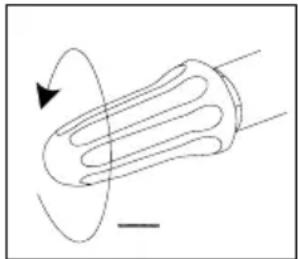
natural_image
Diagram of a solenoid with magnetic field lines and an arrow indicating direction (no text or labels)B. To return the pump pressure to factory settings, turn the unloader valve knob clockwise until it stops.
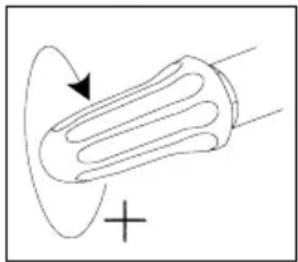
natural_image
Simple line drawing of a bulb-like object with an arrow indicating rotation, no text or symbols presentNOTICE
ADJUST WITH CARE
DO NOT over tighten the pressure control knob. If over tightened, the knob COULD break and result in immediate loss of water pressure and costly repairs to the unit.

NOTICE
SPRAY DAMAGE
High-pressure spray can damage plants and other surfaces. To avoid causing damage, cover plants before spraying near them, refer to the Nozzle Selection table in this manual for correct nozzle selection, and test surfaces before spraying to make sure they are strong enough to withstand high-pressure spray.
HOW TO USE THE SPRAY WAND
The nozzles for the spray wand are stored in the nozzle holder on the panel assembly. Colors on the panel identify nozzle location and spray pattern. Refer to the chart below to choose the correct nozzle for the job to be performed.
| NOZZLE COLOR | SPRAY PATTERN | USES | SURFACES* |
| RED 0° | 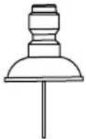 | Powerful pinpoint for spot cleaning of hard, unpainted surfaces or for high reach areas. | Unpainted metal or concrete. DO NOT use on wood. |
| YELLOW 15° | 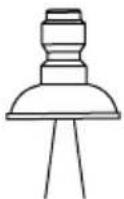 | Intense cleaning of hard, unpainted surfaces. | Grills, driveways, concrete or brick walkways, unpainted brick or stucco. |
| GREEN 25° |  | Standard cleaning nozzle for most applications. | Yard tools, sidewalks, lawn furniture, unpainted siding, stucco, gutters and eaves, concrete, brick surfaces |
| WHITE 40° |  | Cleaning of painted or delicate surfaces. | Auto/RV, marine, wood, painted brick and stucco, vinyl, painted surfaces |
| BLACK (SOAP) |  | Applies cleaning solutions. | Low pressure spray is safe on all surfaces. Always verify compatibility of cleaning solution prior to use. |
*NOTICE! The high pressure spray from your pressure washer is capable of causing damage to surfaces such as wood, glass, automotive paint, auto striping and trim, as well as delicate objects such as flowers and scrubs. Before spraying, check the item to be cleaned to assure yourself that is strong enough to resist damage from the spray of force.
Nozzle Installation
If the engine is running, make sure the trigger lock is in the locked position before removing and installing nozzles.
To place a nozzle into the spray wand, pull the quick-connect coupler back, insert the nozzle, then release the coupler allowing it to snap back in place. Once installed, pull on the nozzle to make sure it's secure.
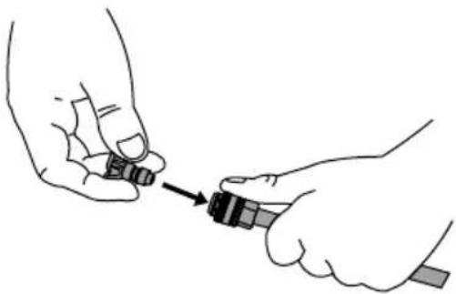
natural_image
Illustration of two hands holding small objects with a directional arrow indicating movement (no text or symbols)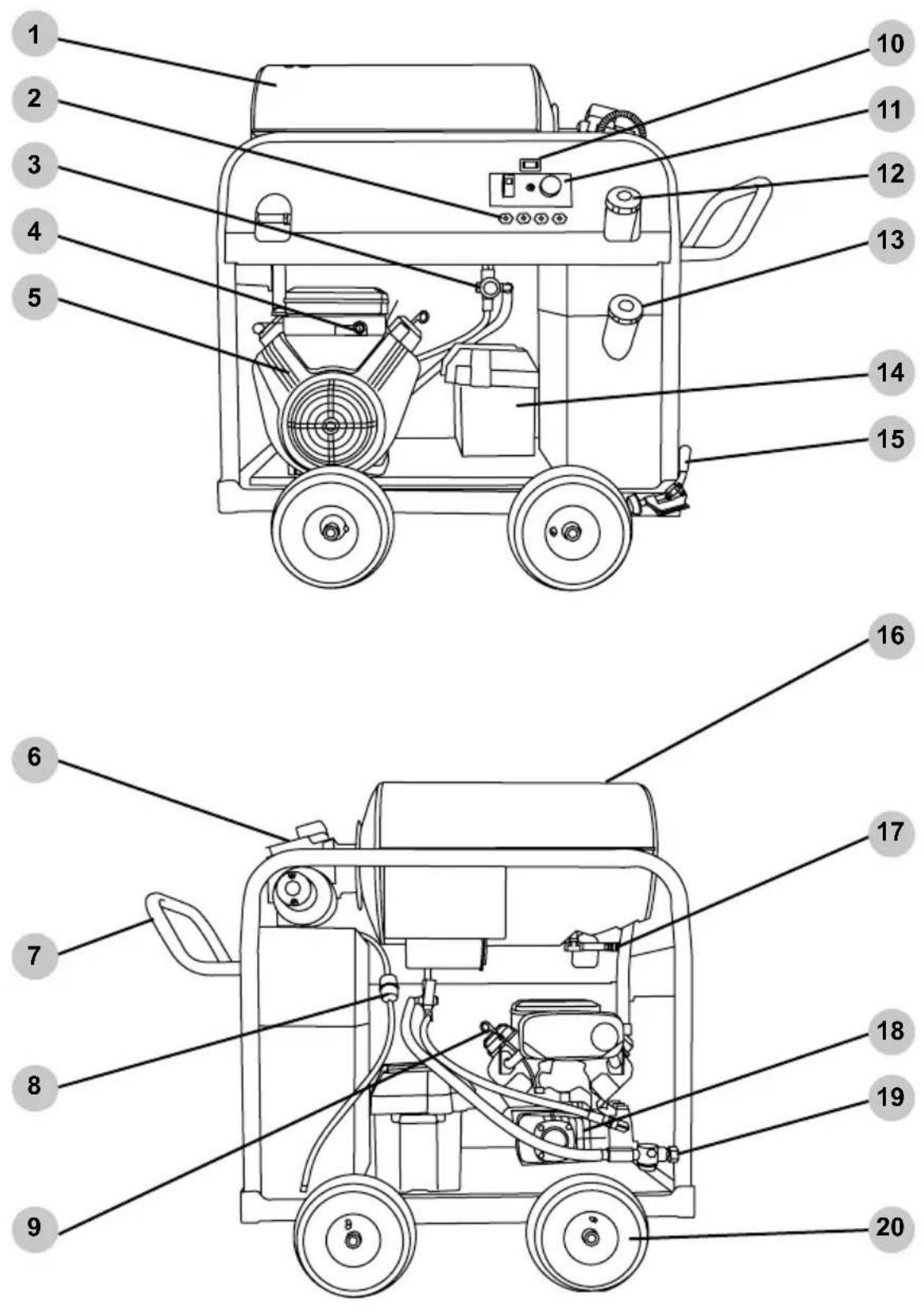
text_image
Technical diagram of a portable gas pump with numbered parts for identificationENGINE POWERED PRESSURE WASHER
These illustrations are to familiarize you with the parts and their locations. Your unit may vary in options and their placement.
text_image
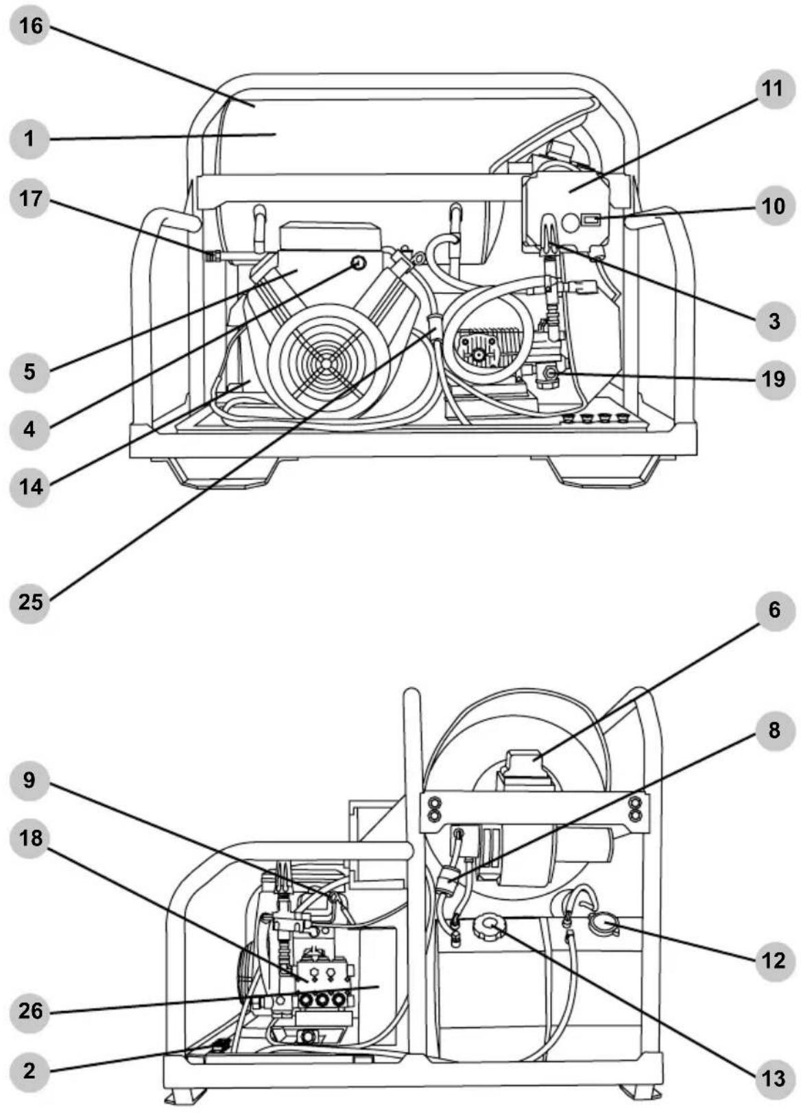
Technical diagram of a device with numbered parts for identification and assembly reference.ENGINE POWERED, SKID MOUNTED POWERED PRESSURE WASHER
These illustrations are to familiarize you with the parts and their locations. Your unit may vary in options and their placement.
text_image
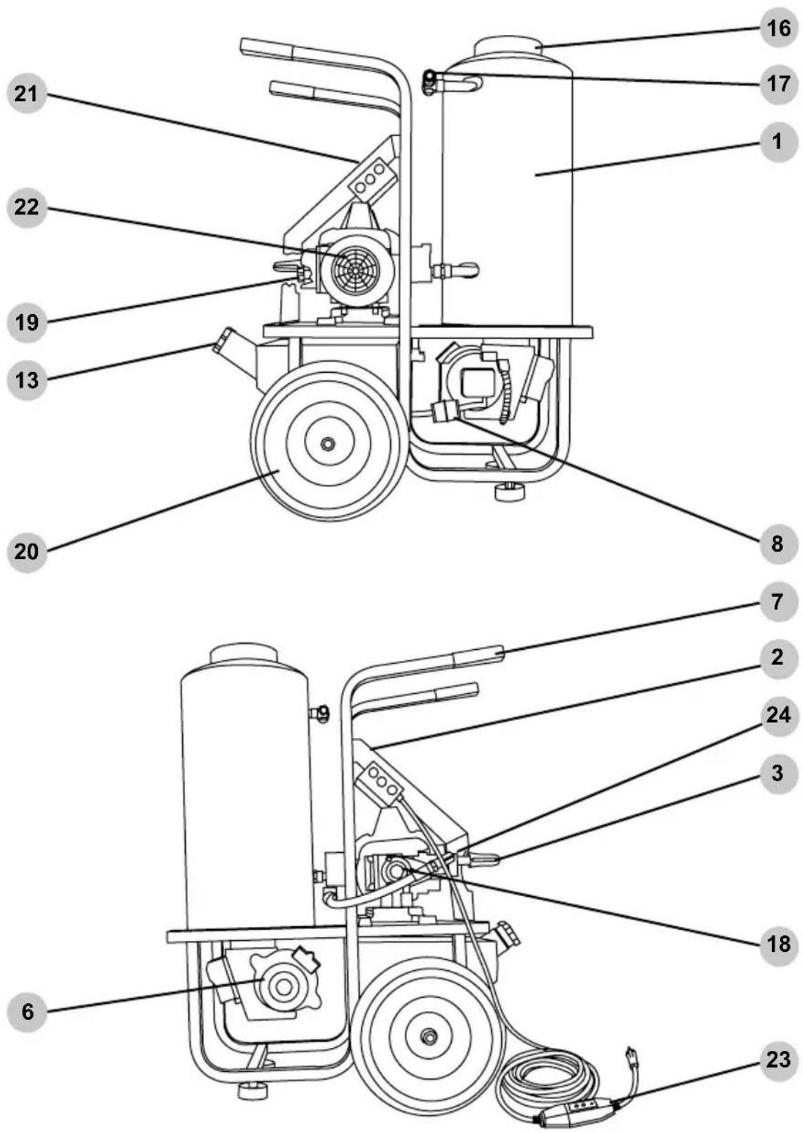
Technical diagram of a fire extinguisher with numbered parts for identificationELECTRIC POWERED PRESSURE WASHER
These illustrations are to familiarize you with the parts and their locations. Your unit may vary in options and their placement.
text_image
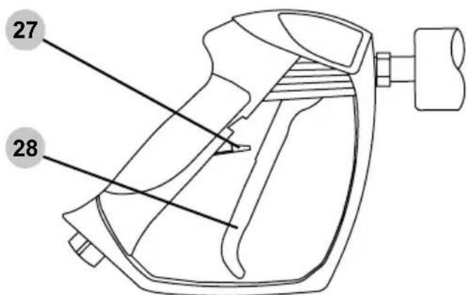
27 28- Burner housing
- Nozzle holders
- Unloader valve, see page 19.
- Engine key start (if applicable). Refer to your Engine Owner's Manual for location and operation.
- Engine. Refer to your Engine Owner's Manual for operating instructions.
- Oil burner assembly
- Handle
- Diesel burner fuel filter
- Oil dipstick. Refer to your Engine Owner's Manual for location.
- Hour meter, see page 41.
- Burner control panel, see pages 39.
- Engine fuel tank filler, see page 27 for gasoline or page 30 for diesel.
- Burner fuel tank filler, see page 39.
- Battery box, see page 30.
- Wheel lock
- Burner exhaust port(s).
- High pressure output, see page 18.
- Pump
- Low pressure water input and filter, see page 18.
- Tire
- Pump and burner ON/OFF switches, see page 37.
- Electric motor
- Electric power supply cord with in-line GFCI protection, see page 38.
- Integrated soap injector, see page 25.
- Gasoline fuel filter
- Belt guard
- Spray gun trigger lock
- Spray gun trigger
Applying cleaning solvents and soaps is a low-pressure operation. NOTE: Only use solvents, detergents and soaps that are designed for use in pressure washers. DO NOT use bleach, caustic or flammable solutions!
- Ensure that the outboard soap injector is connected to the washer high-pressure output. (Fig. 1)
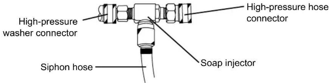
text_image
High-pressure washer connector High-pressure hose connector Siphon hose Soap injectorFig. 1
-
Place the filtered end of the siphon hose into container holding cleaning detergent.
-
If the engine is running, make sure the trigger lock is in the locked position before removing and installing nozzles.
-
Insert the black, low-pressure nozzle into the quick connect fitting of the spray wand, see How to Use The Spray Wand (pg. 20) section of this manual for more information.
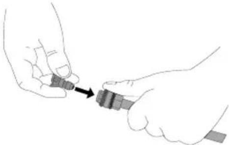
natural_image
Illustration of two hands connecting a small object to a connector (no text or symbols)-
(If equipped) turn the soap control valve counterclockwise to increase soap output and clockwise to decrease soap output.
-
After use of cleaning agents, place the chemical siphon hose into a container of clean water. Draw the clean water through injection system to rinse it throughly. If not rinsed throughly, the injection system can clog from dried detergent.
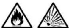

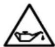
VOLATILE LIQUIDS
Pressure washing with volatile, flammable, or corrosive liquids could cause pressure washer damage, fire, or explosion resulting in severe injury and/or death. To avoid these hazards, use only approved soaps and chemicals, do not attempt to pressure wash with volatile, flammable, or corrosive liquids, and NEVER use bleach.

NOTICE
FILL ENGINE BEFORE USE
The engine is shipped from the factory without oil. Running the engine without oil will result in severe engine damage and void the warranty. To avoid causing engine damage and voiding the warranty, fill the engine with the recommended oil type before starting.
NOTICE
USE CORRECT ENGINE OIL
Oil is a major factor in the performance and service life of any engine. Using the incorrect oil may damage the engine and void the warranty. To avoid causing engine damage and voiding the warranty, check and change oil as required using the correct engine oil.
NOTICE
READ THE ENGINE MANUAL
This manual is a guide on how to use the pressure washer and it's components. The manual for your engine is the repository for all the information you need for the safe operation and maintenance of the engine. Read and understand the Engine Operator's manual before using the engine.
GASOLINE ENGINE
Oil
Before using the pressure washer, you must fill the engine with the correct type and quantity of lubricating oil. When checking and filling the engine with oil, make sure the pressure washer is sitting on a level surface.
Use the Engine Operator's manual during the following steps:
-
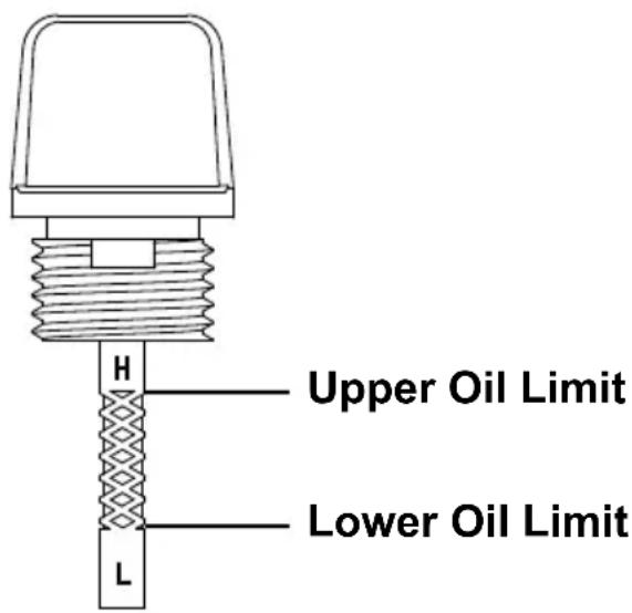
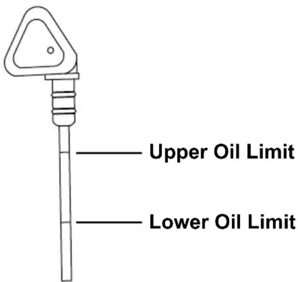
Remove the dipstick from the engine. While the style may differ from the one shown at the right, all will have indication marks to show the correct oil level within the crankcase.
-
The Engine Operator's Manual contains important information as to the weight of oil for your given operating conditions. Typically, SAE 10W-30 API SG or newer, engine oil will suffice for most operating conditions. If you operate in high temperatures or very dirty conditions, consult the Engine Operator's Manual for oil recommendation.
text_image
Upper Oil Limit Lower Oil Limit- Fill the crankcase with the correct type and quantity of oil, DO NOT overfill. Place the dipstick into the engine, but do not screw down (where applicable). Remove the dipstick to verify the oil level. If the level is low, carefully add a small quantity of oil then check the level once again with the dipstick.
- Once the correct level is met, hand tighten the dipstick into the engine body.
NOTICE
LOW OIL SENSOR
The low oil sensor (if equipped) will automatically stop the engine when the oil level falls below the safe limit. To avoid an unexpected shutdown, check the oil level regularly, fill to the upper limit, and always operate engine on a level surface.
GASOLINE ENGINE
Fuel

text_image
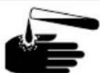
LOOK BEFORE YOU PUMP! —— Ethanol Percentage —— <10% OK NO 15% – 30% – 85%It is imperative to use fresh (less than 30 day old) gasoline with a minimum octane rating of 87 and a maximum ethyl alcohol level of 10%.
Add fuel to the pressure washer by following these steps:
- Check fuel with the engine off and the pressure washer on a level surface.
- Remove the fuel cap to verify the fuel level. For the fuel cap location, see the COMPONENTS LOCATION section of this manual.
-
Use clean, fresh, regular unleaded gasoline with a minimum octane rating of 87. Do not mix fuel and oil! Only use fuel with a maximum ethyl alcohol level of 10%. E15, E20 and E85 are not approved fuels. ENGINE DAMAGE MAY OCCUR BY USING THESE FUELS.
-
Do not fill the fuel tank above the maximum fuel level to allow room for use expansion.
-
Replace the fuel cap. Never run the engine or pressure washer without the fuel cap(s) installed.
NOTE: Using a fuel stabilizer (sold separately) when storing gasoline can help to prevent problems related to ethanol alcohol blended gasoline. Always follow the instructions on the bottle and mix thoroughly.
natural_image
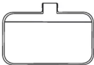
Simple line drawing of a rounded rectangular shape with a central vertical line (no text or symbols)Engine mounted tank
Maximum fuel level
natural_image
Simple line drawing of a 3D rectangular shape with no text or symbolsFrame mounted tank
Maximum fuel level

REFUELING
Gasoline is highly flammable and gasoline vapors are extremely explosive. Fire and explosions can cause severe burns and/or death. Keep gasoline away from flames, sparks, and other ignition sources. Refuel outdoors in a well-ventilated area with the engine stopped and cool. Wipe up any spilled gasoline and allow engine to dry before starting. Keep a fire extinguisher handy while refueling. Do not operate engine with leaks in the fuel system. Do not store gasoline near other flammable materials.
NOTICE
OLD GASOLINE
Old gasoline can create deposits that clog fuel systems causing hard starting and poor performance. Damage caused by old fuel is not covered by warranty. To minimize deposits, avoid old fuel related performance issues, and prevent costly repair work, do not use gasoline that is older than 30 days.
NOTICE
ALCOHOL BLENDS
Using gasoline with an alcohol blend greater than 10% (E10) will damage the engine. Damage caused by using an alcohol blend of 15% (E15), 85% (E85), or any other alcohol blend higher than 10% (E10) is not covered under warranty. To avoid engine damage caused by an alcohol blend that is too high, use gasoline with 10% (E10) alcohol or lower.
NOTICE
GASOLINE ADDITIVES
The use of fuel system cleaning additives can damage the engine and fuel systems. Damage caused by the use of fuel system cleaning additives is not covered by warranty. To avoid engine and fuel system damage, do not use any fuel system cleaning additives.
NOTICE
GASOLINE STORAGE
It is important to prevent gum deposits from forming in essential fuel system parts, such as the carburetor, fuel filter, fuel hose or tank during storage. Alcohol-blended fuels attract moisture, which leads to separation and formation of acids during storage. Acidic fuel and gum deposits can damage the engine's fuel system while in storage. Damage caused by the use of old, stale, or contaminated fuel are not covered under warranty.
NOTICE
READ THE ENGINE MANUAL
This manual is a guide on how to use the pressure washer and it's components. The manual for your engine is the repository for all the information you need for the safe operation and maintenance of the engine. Read and understand the Engine Operator's manual before using the engine.
DIESEL ENGINE
Oil
Before using the pressure washer, you must fill the engine with the correct type and quantity of lubricating oil. When checking and filling the engine with oil, make sure the pressure washer is sitting on a level surface.
Use the Engine Operator's manual during the following steps:
- Remove the dipstick from the engine. While the style may differ from the one shown at the right, all will have indication marks to show the correct oil level within the crankcase.
- The Engine Operator's Manual contains important information as to the weight of oil for your given operating conditions. Typically, SAE 15W-40 or ISO 100 engine oil will suffice for most operating conditions. If you operate in high temperatures or very dirty conditions, consult the Engine Operator's Manual for oil recommendation.
- Fill the crankcase with the correct type and quantity of oil, DO NOT overfill. Place the dipstick into the engine, but do not screw down (where applicable). Remove the dipstick to verify the oil level. If the level is low, carefully add a small quantify of oil then check the level once again with the dipstick.
- Once the correct level is met, make sure the dipstick is tight within the engine block.

NOTICE
LOW OIL SENSOR
The low oil sensor (if equipped) will automatically stop the engine when the oil level falls below the safe limit. To avoid an unexpected shutdown, check the oil level regularly, fill to the upper limit, and always operate engine on a level surface.
text_image
Upper Oil Limit Lower Oil LimitDIESEL ENGINE
Fuel
Add fuel to the pressure washer by following these steps:
- Check fuel with the engine off and the pressure washer on a level surface.
-
Remove the fuel cap to verify the fuel level. For the fuel cap location, see the COMPONENTS LOCATION section of this manual.
-
Use fresh, high-quality #2 diesel fuel for the engine. Fill the tank to a maximum of 1" below the filler neck to allow room for expansion.
-
Replace the fuel cap. Never run the engine or pressure washer without the fuel cap(s) installed.
natural_image
Simple line drawing of a 3D rectangular shape with no text or symbolsMaximum fuel level
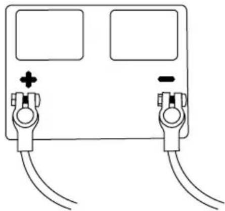
BATTERY CONNECTIONS (if equipped)

RISK OF ACID BURNS
The pressure washer does not come with a battery. You must install a Group 24 sized, automotive style battery before using the pressure washer.
- Remove the cover from the battery box.
- Carefully place the battery into the battery box.
- Place the red, positive (+) battery cable onto the positive (+) battery post. Tighten.
- Place the black, negative (-) battery cable onto the negative (-) battery post. Tighten.
- Place the cover back onto the battery box.
natural_image
Simple line drawing of a device with two ports and two cables, no text or symbols presentWARNING! Always remove the black, negative (-) battery cable first and always connect the black, negative (-) battery cable last.
NOTICE
PUMP PURGING
Running a pressure washer pump without water will severely damage the pump seals and other internal components. To avoid this hazard, make sure your water supply is uninterrupted and at least 5 GPM at 20 PSI, and always purge the air from your pressure washer pump before starting the engine.
WARNING:
INJECTION INJURY
The high pressures created by a pressure washer can cause fluid injection injuries, severe lacerations, amputations and/or death. To avoid these hazards, always aim the spray gun and lance in a safe direction when using the pressure washer and never attempt to touch a leak in a high-pressure hose or fitting.
The pressure washer pump is designed to operate with the water flowing through it. As the water cools the internal components of the pump it also lubricates the seals.
Running the pressure washer pump, no matter for how short of time, without water flowing will severely damage the pump. Damage resulting from running the pump dry is not covered under the warranty. Your pressure washer was a investment in your future, treat it well.
-
Connect the high-pressure hose to both the pressure washer output and the gun. Make sure the hose is uncoiled and not kinked in any way.
-
Connect the garden hose to the water source. Only use cold water for the pressure washer. Turn the water on and allow it to flow for about thirty seconds to remove any debris and trapped air.
-
Turn the water source off. Make sure the water inlet screen is in place and free of debris, then connect the garden hose to the pressure washer input.
-
Once again, turn the water source on. Make sure water is not leaking from any of the joints in the garden hose. If water is leaking, turn the source off, disconnect the hose and replace rubber seals as needed.
-
With the wand pointed away from the pressure washer and any persons, squeeze and hold the trigger until all trapped air is removed from the system. Engage the trigger lock once completed.
-
Once again, make sure none of the hoses or their connections are leaking. NEVER operate the pressure washer with leaking hoses!
natural_image
Line drawing of a spray gun with nozzle and handle, showing internal spray pattern (no text or symbols)Location
Place the pressure washer on a level surface outside in a well-ventilated area before operating. Keep all flammable materials at least five feet away from all sides of the product.
- Never use pressure washer inside a house, garage, or any other kind of enclosure even if doors and windows are open. Run engine outside at least 20 feet (6 meters) away from windows, doors, and vents. Carefully consider wind direction and air currents when using pressure washer outside to avoid breathing in engine exhaust.
- Following the manufacturer's instructions and recommendations, install battery operated carbon monoxide alarms in any occupied buildings near the running engine.
- If you experience headache, nausea, dizziness, sleepiness, or weakness while pressure washer is running, move to fresh air and seek medical attention immediately.

TOXIC FUMES
Engine exhaust contains carbon monoxide, an odorless, colorless, poisonous gas. Running an engine indoors will kill you in minutes. Never use this product inside a house, garage, or any other kind of enclosure even if doors and windows are open. Run engine outside at least 20 feet (6 meters) away from windows, doors, and vents. Carefully consider wind direction and air currents when using this product outside to avoid breathing in engine exhaust. Always use a carbon monoxide detector in any occupied buildings near the running engine.
flowchart
graph TD
    A["NO"] --> B["Car"]
    C["YES"] --> D["Car"]
    style A fill:#f9f,stroke:#333
    style B fill:#ccf,stroke:#333
    style C fill:#cfc,stroke:#333
    style D fill:#fcc,stroke:#333
High Altitude Operation (Gasoline engine only)
This engine will have proper engine performance and emission control when it is operated at or below an altitude of 5000 feet (1524 meters). This engine requires a high-altitude carburetor kit to ensure proper engine performance and emission control when operated at altitudes above 5000 feet (1524 meters). Operating the machine with the wrong engine configuration above 5000 feet (1524 meters) may increase its emissions, decrease fuel efficiency, and hurt performance. To obtain a high altitude carburetor kit, contact your nearest authorized service center.
NOTICE
ALTITUDE
Operating the engine with a high-altitude carburetor jet kit at an altitude below 5000 feet (1524 meters) will cause the engine to run too hot. Overheating the engine could result in serious engine damage. To avoid this hazard, make sure the correct carburetor kit is installed and the air/fuel mixture is set correctly for your altitude.
Operating Conditions
Before each use, check for loose or damaged parts, leaks, and/or any other condition that may affect proper operation. Repair or replace all damaged and/or defective parts immediately. Always keep all safety guards in place and in proper working order. For safety reasons, the manufacturer recommends all maintenance and repairs be performed by an authorized service center.
Before starting engine, remove any excessive dirt and debris from cooling vents, exhaust, and starter recoil areas. Always operate the pressure washer on a level surface and never move or tip the pressure washer while operating. Use pressure washer only for its intended purpose. If you have questions about the proper use of your pressure washer, please contact customer support at 1-877-362-4271 or cservice@fna-group.com.

WARNING:
UNTRAINED OPERATION
Untrained adults and children can be seriously injured or killed if allowed to incorrectly operate or play with running pressure washer. To avoid these hazards, be sure anyone operating the pressure washer receives proper instructions, understands safe operation, and has read the owner's manual before operating this product. Do not let children operate the pressure washer without parental supervision. Keep children and pets away from the pressure washer while it is running. Always turn off the pressure washer before leaving the area.
WARNING:
Failure to inspect this product before use could create a hazardous situation resulting in product damage, serious injury, and/or death. To avoid these hazards, inspect the pressure washer before each use. Check for loose or damaged parts, signs of oil or fuel leaks, missing guards, plugged cooling vents, or any other condition that may affect proper operation. Repair or replace all damaged or defective parts and keep all safety guards in place and in proper working order before using the pressure washer.

INJECTION INJURY
The high pressures created by a pressure washer can cause fluid injection injuries, severe lacerations, amputations, and / or death. To avoid these hazards, always aim the spray gun and lance in a safe direction when using the pressure washer and never attempt to touch a leak in a high-pressure hose or fitting.

HOT SURFACES
A running engine produces heat. The surfaces of the engine, other related components, and engine exhaust gas get hot enough to cause mild moderate burns or ignite materials on contact. To avoid burns, do not touch engine surfaces or exhaust gases while operating and allow engine to cool completely before moving, touching, or performing any maintenance. To avoid a fire, keep all flammable materials at least five feet away from all sides of the product.
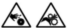
MOVING PARTS
This product has many parts that move at high speeds. Moving parts can cause crushing injuries, broken bones, severe lacerations, and/or traumatic amputations. To prevent injury, never place fingers, hands, feet, or other body parts near running engine. Never operate product with covers, shrouds, or other guards removed. Do not wear loose-fitting clothing, dangling drawstrings, or any other hanging items that could become entangled in moving parts while operating. Tie up long hair and remove jewelry before operating.

RAPID RETRACTION
Rapid retraction (also known as kickback) of the engine recoil starter cord will pull your hand and arm towards the engine faster than you can let go of the handle resulting in sprains, broken bones, lacerations, and/or traumatic amputations. Kickback is often caused by internal engine failure, and/or improper starting techniques. To avoid kickback follow the appropriate maintenance schedule, starting instructions and have repair work done by an authorized service center.


OPERATING CHECKLIST
Attempting to start the engine incorrectly or using the pressure washer incorrectly can result in engine and/or pressure washer damage, and may cause serious injury or death. To avoid these hazards, be sure to read, understand, and follow the steps outlined in the OPERATING CHECKLIST section of the owner's manual before starting the engine, and follow all the guidelines for proper use of the pressure washer.

PUMP DAMAGE
Running the pressure washer for more than two minutes without the spray gun trigger pulled will overheat the pump and possibly cause damage. The thermal relief valve will open and spray water to help cool the pump as it overheats. To avoid overheating the pump, shut off the machine if not being used for longer than two minutes.
NOTE: Allow engine to warm for 1-2 minutes before using the product.
Starting the Engine (Gasoline engine - Electric start)
- Completely read and understand the Engine Owner's Manual you received along with this manual.
- Complete the steps in the OPERATING CHECKLIST, CONNECTING HOSES and PURGING AIR FROM THE PUMP sections of this manual before starting the engine.
- For a COLD engine, set the choke to "CHOKE" -or- "CLOSED".
- Set the throttle to "FAST" (if equipped).
- Turn the fuel valve to "ON" -or- "OPEN" (if equipped).
- Turn the key past "ON" to "START" and hold for no longer than five seconds. If the engine does not start within five seconds, release the key and wait one minute before trying again. WARNING: Allowing the starter to constantly crank will damage the starter! If the engine does not start after two attempts, refer to the TROUBLESHOOTING section for help.
- Once the engine has started, move the choke to "OPEN" -or- "RUN".
Starting the Engine (Gasoline engine - Recoil start)
- Complete steps 1 through 5, from above.
- Grasp the recoil handle and slowly pull until resistance is felt. Pull swiftly to start the engine. If the engine does not start after two pulls, squeeze the gun trigger to release stored pressure.
- Once the engine has started, move the choke to "OPEN" -or- "RUN".
NOTICE
PUMP DAMAGE
Running the pressure washer for more than two minutes without the spray gun trigger pulled will overheat the pump and possibly cause damage. The thermal relief valve will open and spray water to help cool the pump as it overheats. To avoid overheating the pump, shut off the machine if not being used for longer than two minutes.
- Completely read and understand the Engine Owner's Manual you received along with this manual.
- Complete the steps in the OPERATING CHECKLIST, CONNECTING HOSES and PURGING AIR FROM THE PUMP sections of this manual before starting the engine.
text_image
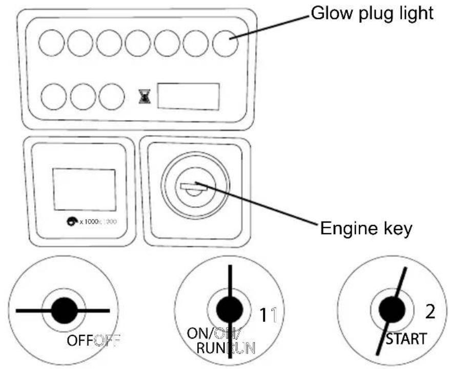
Glow plug light Engine key OFFOFF ON/ON RUNUN 1 2 STARTOFF Position Position 1

text_image
2 STARTPosition 2
- Turn the engine key to the 1st position.
- Wait for the orange Glow Plug light to turn off.
- Turn the key to the 2nd position to start the engine. Once the engine has started, allow the key to return to the 1st position.
WARNING: Allowing the starter to constantly crank will damage the starter! After a maximum of 20 seconds cranking, allow the starter to cool one minute before trying again. If the engine does not start after two attempts, refer to the TROUBLESHOOTING section for help.
NOTICE
PUMP DAMAGE
Running the pressure washer for more than two minutes without the spray gun trigger pulled will overheat the pump and possibly cause damage. The thermal relief valve will open and spray water to help cool the pump as it overheats. To avoid overheating the pump, shut off the machine if not being used for longer than two minutes.


ELECTRICAL GROUNDING
Improper connection of the equipment grounding conductor can result in the risk of electrocution. If in doubt of proper grounding, have a licensed electrician verify the installation of the receptacle. Do not modify the plug provided with the product if it will not fit the receptacle installed. Do not use any type of adapter with this product.
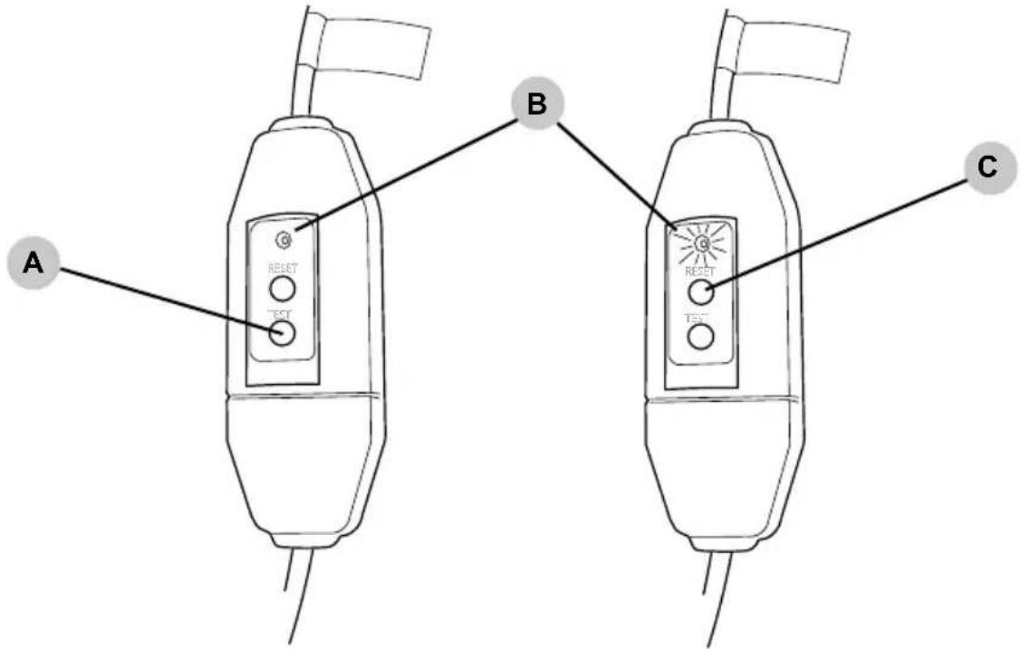
- Complete the steps in the OPERATING CHECKLIST, CONNECTING HOSES and PURGING AIR FROM THE PUMP sections of this manual before turning on the motor.
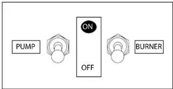
- Verify the PUMP ON/OFF switch is in the "OFF" position.
flowchart
graph LR
    A["PUMP"] --> B["ON"]
    B --> C["OFF"]
    C --> D["BURNER"]
- Plug the power supply cord into a grounded, three prong receptacle. DO NOT use an extension cord. If the power supply cord will not reach, move the pressure washer closer to the receptacle.

ELECTROCUTION HAZARD
Use of an extension cord could cause shock or burn resulting in death or serious injury. DO NOT use an extension with this electric pressure washer. Your home's electrical circuit receptacle or extension cord may not provide lifesaving ground fault circuit interrupting protection.
-
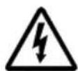
Test the ground fault circuit interrupter (GFCI) (if equipped).
-
Press the TEST button (A). The indicator light (B) should now be dark (OFF).
text_image
A B C RESET TEST RESET TEST-
Press the RESET button (C). The indicator light (B) will now be illuminated (ON). CAUTION - DO NOT use the pressure washer if the above test fails.
-
Flip the PUMP switch to ON. The pressure washer is now ready to be used.
flowchart
graph LR
    A["PUMP"] --> B["ON"]
    B --> C["OFF"]
    C --> D["BURNER"]

RISK OF BURNS
The surfaces around the burner exhaust and the discharged exhaust are VERY HOT. Keep away from this area. DO NOT allow the hoses to contact the burner exhaust in anyway. DO NOT allow children to operate or be in the vicinity of the pressure washer at any time.

RISK OF EXPLOSION
The burner will shutoff every time you release the trigger. DO NOT use the pressure washer if the burner fails to shut off when the trigger is released.
FILLING THE BURNER FUEL TANK
- Check fuel with the engine off and the pressure washer on a level surface.
- Remove the fuel cap to verify the fuel level. For the fuel cap location, see the COMPONENTS LOCATION section of this manual.
- Use fresh, high-quality #2 diesel fuel for the burner. Fill the tank to a maximum of 1" below the filler neck to allow room for expansion.
- Replace the fuel cap. Never run the engine or pressure washer without the fuel cap(s) installed.
natural_image
Simple line drawing of a rectangular shape with a jagged top edge (no text or symbols)Maximum fuel level
STARTING THE BURNER
- Complete the steps in the OPERATING CHECKLIST, CONNECTING HOSES and PURGING AIR FROM THE PUMP sections of this manual before turning on the motor.
- Start the engine as outlined in STARTING THE ENGINE section of this manual.
- Place the burner ON/OFF switch in the ON position.
- (If equipped) Turn the thermostat to the desired temperature.
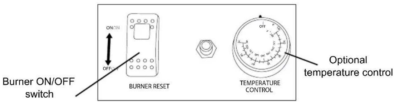
text_image
ON ON OFF Burner ON/OFF switch BURNER RESET TEMPERATURE CONTROL Optional temperature control
NOTICE
PUMP DAMAGE
Turning off the water supply to your pump with the engine running will damage the pump. Damage caused by running the pump without water is not covered under warranty. To avoid this hazard always turn off the engine before shutting off the water supply.
NOTICE
CHEMICAL CLEANERS
Using chemical cleaners and/or corrosive liquids can damage the pressure washer seals and internal components. Damage caused by chemical cleaners and corrosive liquids is not covered under warranty. To avoid these hazard, only used approved cleaning chemicals, never use bleach, and always run clean water through the pressure washer after using cleaning chemicals.
- Turn the burner control switch to OFF.
- Squeeze the trigger and allow the water to flow until the spray wand becomes cool to the touch, minimum of two minutes.
- If you used soap or detergent, place the siphon hose into a bucket of clean water. With the black nozzle attached to the wand, squeeze the trigger and allow water to flow until all signs of soap are gone.
- Set the trigger lock.
- If your unit is electric powered, turn the pump ON/OFF switch to OFF.
- For a gasoline or diesel engine, move the throttle to slow (if equipped). Turn the key or engine switch to OFF.
- Turn the fuel valve to OFF or CLOSED (if equipped).
- Turn the water source off.
- Squeeze the trigger to release any stored pressure from the hose.
- Disconnect the garden from both the source hose bibb and the pump inlet.
- Disconnect the high-pressure hose from the pressure washer outlet. Drain the hose then carefully coil.
- Refer to the STORAGE section for proper short or long-term storage instructions.
PREPARATION
- Read all warnings and instructions in this and all other manuals that may have come with the pressure washer.
- Remove all toys, bicycles, lawn furniture, etc. from the work area.
- Sweep any loose dirt and debris from the surface you will be pressure washing.
- Cover nearby plants to protect them from over spray and detergent.
- Only use the white, 40^ nozzle when washing windows or painted items like automobiles. Always start far away and move closer with care.
- If you are using the pressure washer to prepare siding for painting and the existing paint my be from before 1977, lay down tarps to collect the paint chips. They may contain lead and need to be disposed of at a proper disposal facility.
- Use only detergents or soaps that are approved for pressure washer use.
PRESSURE WASHING
- A wider spray equals faster cleaning, while a tighter spray equals deeper cleaning.
- Do not aim the nozzle straight at a surface. Hold the wand at a 45^ angle to the surface at a distance that cleans well without causing damage.
- Keep the nozzle about four feet away from siding to prevent damage to the surface.
- Start washing at the bottom, move your way upward then rinse from the top down.
- Avoid driving water behind siding, trim and into window frames.
- When using soap, work on smaller areas and do not let the soap dry.
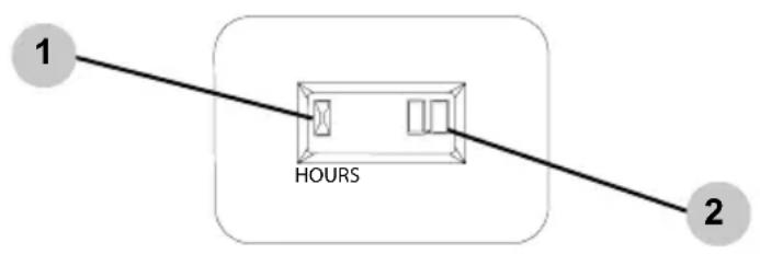
HOUR METER (If equipped)
The hour meter keeps track of the time the pressure washer is running. The hour glass icon flashes when the engine is running to signify the meter is tracking the hours of operation. The digital time display shows the recorded hours of operation. Use this information for preventative maintenance intervals.
For hour meter location see the COMPONENT LOCATION section of this manual.
flowchart
graph LR
    1["1"] --> HOURS["HOURS"]
    2["2"] --> HOURS
    style HOURS fill:#f9f,stroke:#333
- Hour glass icon
- Digital time display
Your pressure washer has been produced with the highest quality materials and craftsmanship. As the owner, you have certain responsibilities for the correct care of the equipment. Attention to regular preventative maintenance procedures will assist in preserving the performance of the equipment.
Contact your local authorized service center for maintenance. A small investment in preventative maintenance will add many hours to the life of the pressure washer. Perform maintenance more often under severe operating conditions. Do not spray high-pressure water onto the machine at any time.
For safety reasons, the manufacturer recommends all pressure washer service and repairs be performed by an authorized service center. All warranty repairs and replacements must be performed by an authorized distributor or service center.
To find an authorized service center near you, make a warranty claim or get authorized warranty repairs, call 1-877-362-4271 or email us at cservice@fna-group.com
It is the responsibility of the owner and/or operator to have all scheduled maintenance completed before operating the pressure washer. Be sure to follow the inspection and maintenance recommendations as listed in all the manuals that came with this unit.
CLEANING THE PRESSURE WASHER
Always clean the pressure washer with the engine off and cool. To clean the pressure washer, first use compressed air at or below 20 PSI to clear dirt and debris from the pressure washer surface, vents and cooling slots. Next, wipe the exterior surface with a damp cloth.
PREWORK INSPECTION
Before each use, check the pressure washer for leaks, loose or damaged parts and any other condition that may affect proper, safe operation. Be sure all the safety guards are in place and in proper working order. Inspect all cooling slots to ensure they are clean and unobstructed.
Repair and replace all damaged or defective parts immediately. For safety reasons, the manufacturer recommends all pressure washer service and repairs be performed by an authorized service center.
CONNECTIONS
Hose, spray gun and pump connections should be cleaned and lubricated with a thin film of lithium grease regularly to prevent O-ring damage and leaks.
Nozzle Cleaning
If a nozzle becomes clogged, the pump may pulsate and spray patterns could change. If the nozzle is not cleaned, excessive pressure may develop possibly damaging the pump, or other accessories. Inspect nozzles before using them and follow the instructions in this section for the proper nozzle cleaning procedure.
- Shut off the pressure washer.
- Turn off the water supply.
- Point the spray gun in a safe direction and squeeze the trigger to relieve water pressure.
- Set the trigger lock.
- Remove the nozzle from the lance quick connector.
- Clear any obstructions from the nozzle by inserting the nozzle cleaning tool provided.
natural_image
Diagram of a mechanical component with a shaft and housing, showing bidirectional movement between two parts (no text or symbols)- Rinse any loose debris from the nozzle by directing a running garden hose into the output of the nozzle for at least 30 seconds.
natural_image
Diagram showing a connector being inserted into a housing, with no text or symbols present.Water Inlet Filter
Before each use, check the inlet filter and clean by following the steps below. Never operate the pressure washer without the inlet filter properly installed.
- Remove the filter from the garden hose coupler.
-
Use water from a running garden hose to clean both sides of the filter.
-
Insert the cleaned filter into the pump inlet with the convex side facing out.
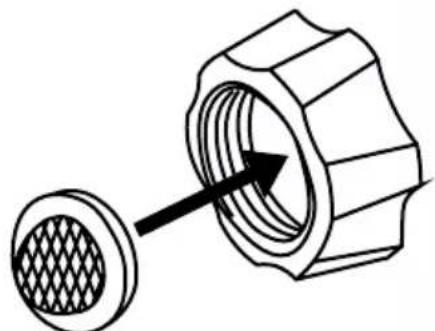
natural_image
Technical illustration of a mechanical component with a meshed circular base and arrow indicating direction (no text or symbols)ENGINE MAINTENANCE
Before each use, check the engine for loose or damaged parts, signs of oil or fuel leaks and/or any condition that may affect proper, safe operation. Always keep all guarding in place and proper working order. Repair or replace defective parts immediately.
For safety reasons, the manufacturer recommends all engine service and repairs (including emission control devices and systems) to be performed only by an authorized service center. All warranty work and replacements must be performed by an authorized service center.
For all other information on engine maintenance, refer to the engine manual.
PUMP MAINTENANCE
The pump was filled with oil at the factory. Refer to the MAINTENANCE SCHEDULE CHART for proper service intervals and oil type.
Note: Your pump may vary from the one illustrated.
- Oil sight glass
- Oil fill plug
- Oil drain plug (not shown)
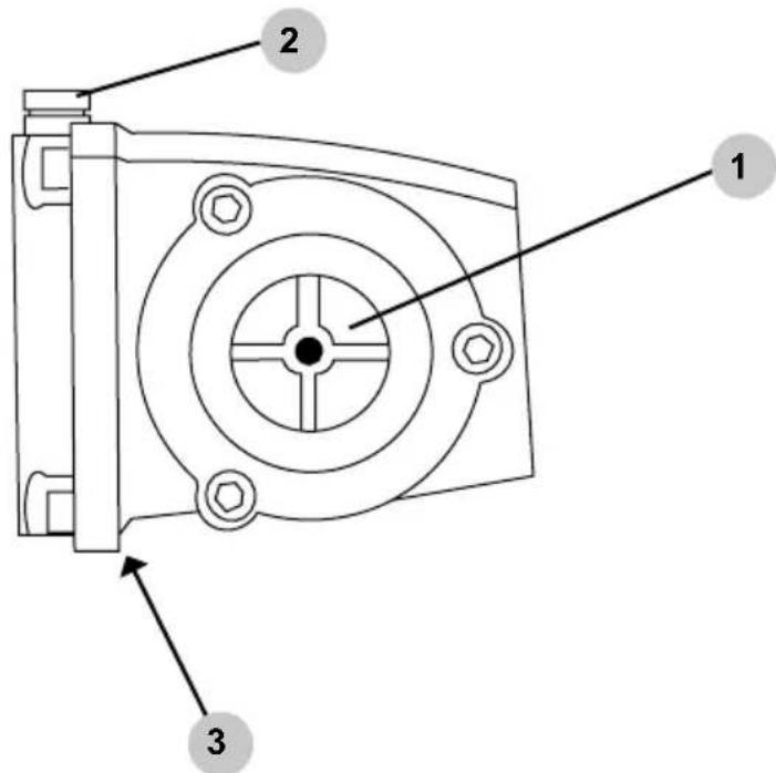
text_image
1 2 3How to change the pump oil
- Loosen the pump oil fill plug.
- Place a container under the oil drain plug.
- Remove the oil drain plug.
- After the oil has drained, insert the oil drain plug; tighten securely.
- Refer to MAINTENANCE SCHEDULE CHART for the proper oil type for your pump.
- Make sure the oil level meets but does not exceed the dot in the center of the sightglass.
- Insert the oil fill plug; tighten securely.
MAINTENANCE SCHEDULE CHART
NOTICE: Not all maintenance items listed below apply to all models.
| Engine Oil Inspect Daily | ||
| Change | After the first 10 hours, then every 50 hours especially in high ambient temperature | |
| Every 100 hoursFilter | ||
| Air Cleaner | Inspect | Every 25 hours |
| Clean | Every three months | |
| Diesel engine coolant Check daily (Maximum 50% antifreeze) | ||
| Battery level Check monthly Replace every 2 years | ||
| Engine Fuel Filter | 500 hours or 6 months | |
| Spark Plug Maintenance | 500 hours or 6 months | |
| Clean Fuel Tank(s) | Annually | |
| Replace Fuel Lines | Annually | |
| Pump Oil Inspect | Daily | |
| Change | First 25 hours, then every 3 months or 150 hours | |
| Replace Burner Fuel Filter Every 6 months (More often if fuel quality is poor) | ||
| Remove Burner Soot | Annually | |
| Burner Adjustment / Cleaning | Annually | |
| De-scale Heating Coil | Annually | (More often if required) |
| Replace spray Nozzle | Every 6 months | |
| Replace Quick Connectors Annually | (More often if required) | |
| Clean water inlet filter | Weekly | |
| Replace high-pressure hose | Annually | (More often if required) |
| Tires / wheel bearings | Monthly | |
| Belts | Tighten Every 6 months | |
| Inspect / Replace Annually | ||
| Description | Oil Type | Capacity (5) |
| Gasoline Engine | SAE 10W 30 motor oil (4) | .63 to 3qt |
| Diesel Engine | SAE 15W 40 or ISO 100 (4) | 1.7 - 3.3qt |
| Pump, AAA | SIMPSON PUMP OIL or SAE 15W 40 | 11 - 42oz |
| Pump, CAT (1) | ISO 68 Hydraulic Oil | 11 - 42oz |
| Pump, COMET (2) | SAE 15W 40 or ISO 100 | 11 - 42oz |
| Pump, General (3) | SAE 15W 40 or ISO 100 | 11 - 42oz |
| (1) CAT Pumps® is a registered trademark of Diversified Dynamics Corporation.(2) COMET Pumps® is a registered trademark(3) General Pumps® is a registered trademark of Interpump Group S.p.A.(4) Refer to the engine manual for proper weight per operating condition.(5) Refer to the manual for the proper amount. | ||
STORING FOR TWO MONTHS OR LESS (GASOLINE)
- Fill fuel tank per the ENGINE PREPARATION section of this manual then add a fuel stabilizer per the manufacture's recommendations. NOTE: Using a gasoline fuel stabilizer (sold separately) when storing gasoline may help prevent problems related to alcohol blended fuels in outdoor power equipment engines. Always follow the instructions provided by the fuel manufacturer to mix and use correctly.
- Complete the steps in the OPERATING CHECKLIST, CONNECTING HOSES and PRIMING THE PUMP sections of this manual.
- With the water running, start the engine per the STARTING section of this manual and allow it to run for ten minutes. This will allow the stabilized fuel to circulate the entire fuel system. Be sure to squeeze the trigger to keep water flowing through the pump and spray gun to avoid overheating.
- Turn the key or engine switch to OFF.
- Squeeze the spray gun trigger to relieve stored pressure. Drain the spray wand and the high-pressure hose. Carefully coil the high-pressure hose.
- Allow the engine to cool completely.
- Protect the pump by using SIMPSON Pump Guard per the USING PUMP GUARD section of this manual.
- Store the pressure washer in a clean, dry area out of direct sunlight.
STORING FOR TWO MONTHS OR LESS (DIESEL)
Follows steps 1 - 8 from above by using a diesel fuel stabilizer.
STORING FOR TWO MONTHS OR LESS (ELECTRIC POWERED)
- Squeeze the spray gun trigger to relieve stored pressure. Drain the spray wand and the high-pressure hose. Careful coil the high-pressure hose.
- Protect the pump by using SIMPSON Pump Guard per the USING SIMPSON PUMP GUARD section of this manual.
- Store the pressure washer in a clean, dry area out of direct sunlight.
STORING FOR TWO MONTHS OR MORE (GASOLINE)
- Allow the engine to cool and squeeze the spray gun trigger to relieve stored pressure.
- Remove all fuel from the fuel tank, fuel lines and carburetor by loosening the drain screw at the bottom of the carburetor. Drain the fuel into an appropriate container.
-
Change the engine oil per the Engine Owner's Manual
-
Remove any dirt and debris from the area around the spark plug(s). Using a spark plug socket & wrench, remove the spark plug(s).
-
Pour 0.5 ounces (15ml) of new oil into the engine combustion chamber(s). Turn the starter key to START for two seconds -or- slowly pull the recoil cord twice to lubricate and protect the cylinder(s).
-
Reinstall the spark plug(s) by hand then tighten with a socket wrench to the correct torque per the Engine Owner's Manual.
-
Disconnect the black, negative (-) battery lead from the battery.
-
Disconnect the red, positive (+) battery lead from the battery.
-
If the pressure washer will be kept in a cold location, move the battery to a warm location for long term storage -or- use an electronic battery maintainer to keep the battery warm and charged during the cold storage.
-
Drain the spray wand and the high-pressure hose. Carefully coil the high-pressure hose.
-
Protect the pump by using SIMPSON Pump Guard per the USING SIMPSON PUMP GUARD section of this manual.
-
Store the pressure washer in a clean, dry area out of direct sunlight.
STORING FOR TWO MONTHS OR MORE (DIESEL)
- Follows steps 1 - 7 from STORING FOR TWO MONTHS OR LESS (GASOLINE) by using a diesel winter treatment stabilizer. This will keep the diesel from gelling in subfreezing weather.
- Disconnect the black, negative (-) battery lead from the battery.
- Disconnect the red, positive (+) battery lead from the battery.
- If the pressure washer will be kept in a cold location, move the battery to a warm location for long term storage -or- use an electronic battery maintainer to keep the battery warm and charged during the cold storage.
- Store the pressure washer in a clean, dry area out of direct sunlight.
STORING FOR TWO MONTHS OR MORE (ELECTRIC POWERED)
Follow the same steps as STORING FOR TWO MONTHS OR LESS (ELECTRIC POWERED)
TRANSPORTATION

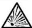

TRANSPORTATION
Leaving the pressure washer in an enclosed space where temperatures can rise on a transport vehicle may cause fuel to vaporize and possibly explode. Fire and explosions can cause severe burns and/or death. To avoid leaking or vaporizing fuel, secure the pressure washer in a well ventilated area out of direct sunlight and other heat sources and do not transport the pressure washer on rough roads unless the fuel has been drained beforehand.
- Turn the engine control switch to the OFF position.
- To prevent fuel spillage when transporting, make sure the fuel cap(s) are tight and the pressure washer is kept upright on a level surface.
- Secure the pressure washer with straps or tie downs rated for twice the weight of the pressure washer to keep it from tipping over or sliding.
CAUTION: Never operate the pressure washer while it is on the transport vehicle.

NOTICE
PUMP DAMAGE
Leaving water inside the pump during freezing weather will cause severe damage to the pump. To avoid costly damage, always treat the pump with SIMPSON® Pump Guard to remove the trapped water and to fill the pump with a lubricating, antifreeze solution.
SIMPSON® Pump Guard (purchase separately) is formulated to protect your pump from freezing damage while lubricating the internal seals. Pump Guard should be used throughout the season to keep the seals pliable and well lubricated. Before storing the unit for winter or for when there is a chance of freezing weather, use pump guard to remove all traces of water from the internal cavities while filling them with an antifreeze solution.
Simply use Pump Guard by following these easy steps:
- Screw the Pump Guard adapter into the garden hose input on the pump.
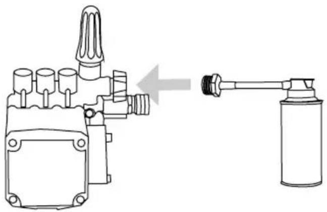
natural_image
Technical line drawing of a mechanical device with a pipe fitting and a cylindrical container (no text or symbols)- Press and hold down on the button until all the water and the Pump Guard starts to come out of the high pressure port.
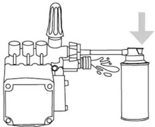
natural_image
Diagram of a mechanical device with a spray bottle and pump, showing fluid flow direction (no text or labels)- Unscrew the Pump Guard from the pump then prepare the pressure washer for storage as outlined in STORAGE AND TRANSPORTATION.
NOTE: Probable causes are listed with the most likely cause first. Repairs should be made by qualified service technicians only.
POWER SYSTEM: GASOLINE OR DIESEL DRIVEN
| Problem Probable | Cause Remedy | |
| Engine will not start or crank over.(See Engine Owner's Manual for further engine troubleshooting) | Battery dead (if equipped) Charge or replace battery, add electrolyte if battery is new | |
| Dirty battery contacts Clean contacts | ||
| Battery cables disconnected Connect or replace damaged cables | ||
| Engine, pump or gearbox is seized | ||
| Key switch, solenoid or starter on engine defective | ||
| Pump is seized Replace pump or bearing | ||
| Engine will not start but will crank over.(See Engine Owner's Manual for further engine troubleshooting) | Engine power switch is off or defective | Check engine power switch |
| Low oil shutdown is activated (if equipped) | Add oil to engine, check more frequently | |
| Low on fuel | Fill with the appropriate fuel, bleed injector pump on diesel engines | |
| Fuel filter is clogged | Replace or clean fuel filter, bleed injector pump on diesel engines | |
| Engine flooded or starved | Gasoline engines only - Choke only as required | |
| Old or dirty fuel | Drain and replace with fresh, clean fuel | |
| Engine bogs down under load, whenever spray gun is triggered(See Engine Owner's Manual for further engine troubleshooting) | Engine needs to be repaired Seek certified service | |
| Operating in high elevation | Lower the pressure on the unit and check for correct engine speed (RPM) | |
| Incorrect nozzle in lance | Replace with correct nozzle size | |
| Unloader valve improperly adjusted | Adjust unloader valve | |
| Problem Probable | Cause Remedy | |
| Electric motor does not start | No electric power | Check cord, plug, socket, GFCI and breaker |
| Thermal overload in the motor or starter has been tripped | Reset manual overload by depressing the thermal switch on the outside of the motor after the motor has cooled.CAUTION: Automatic overload will restart the motor automatically once the motor has cooled. | |
| Power switch inoperative Check | power switch | |
| Electric motor or wiring failure | Replace or repair motor and/or wiring | |
| No water pressure at inlet | Connect to appropriate water supply | |
| Machine will not auto start (if equipped) | Must have adequate water supply | Check for correct pressure and gallonage |
| Coil scale buildup | Descale coil for better water flow | |
| Check filter screen and inlet pressure | Pull trigger gun to check auto-start function | |
| Pressure switch on unloader is faulty | Replace | |
| Timer is faulty | Remove leads from timer at control end, see if machine shuts off after time out, replace if defective |
PUMPING SYSTEM
| Problem Probable | Cause Remedy | |
| Trigger gun leaks or will not shut off | Debris in gun valve assembly | Clean valve assembly or replace gun |
| Pump runs but there is no spray pressure | Water turned off | Turn water on |
| Nozzle is plugged | Clean or replace with proper size nozzle | |
| Chemical injection valve is open / hose not in solution | Close soap valve or sub-merge detergent siphon tube into solution | |
| Hot water coil obstructed Remove | ve obstruction or descale the coil | |
| Pump dry, needs to be primed | Open fitting on high pressure pump until water flows |
PUMPING SYSTEM
| Problem Probable | Cause Remedy | |
| Pump runs but has low spray pressure | Nozzle not installed | Install proper sized nozzle |
| Dual wand valve is open Dual w | and valve must be closed and high pressure nozzle installed | |
| Leaky discharge hose or quick connect connector | Replace hose or connector | |
| Inlet strainer clogged | Clean and check more frequently | |
| Worn or wrong sized nozzle | Replace with proper size nozzle | |
| Belt slippage | Tighten or replace worn belt | |
| Unloader valve worn or improperly adjusted | Install pressure gauge on pump head to adjust pres- sure. Check valve seat on Unloader Valve | |
| Air leak in inlet plumbing | Reseal fittings and inspect inlet hoses for air leaks | |
| Pump runs but there is erratic, fluctuating pressure | Inadequate incoming water supply | Increase water supply flow |
| Stuck inlet or discharge valves | Clean out or replace worn valves | |
| Restricted inlet or air entering the inlet plumbing on the pump | Check fittings and hose for air tight seal, clean inlet strainer screen | |
| Leaking high-pressure seals | Replace seals | |
| Leaking low-pressure seals | Pressure feed the pump and replace low-pressure seals if water leaks from pump | |
| Excessive crankshaft play or loud, knocking noise in pump | Broken or worn bearing or connecting rod in crankcase | Replace pump or bearing or connecting rod |
| Oil leaking from pump | Loose drain plug or damaged seal | Locate point of oil leakage and replace damaged O-ring or seal |
| Leaking crankshaft oil seal | Replace seals | |
| Leaking oil sight glass seal | Replace seals | |
| Leaking piston oil seal | Replace seals. Install cor- rect pump oil | |
| Water is emitted from chemical siphon tube | Check valve malfunctioning | Repair or replace check valve |
| Problem Probable | Cause Remedy | |
| Inlet injection will not siphon detergent | Strainer clogged | Clean or replace. Rinse after each use. |
| Detergent valve not open or clogged | Open valve then clean. Replace if necessary | |
| Strainer not submerged in solution | Submerge strainer, replenish chemical if needed | |
| Detergent hose cut or kinked | Inspect hose, replace if necessary | |
| Downstream injector will not siphon detergent | Adjustable knob on injector is closed (if equipped) | Open by turning counter clockwise |
| Unit not in low pressure mode | Open dual wand (if equipped) or install soap nozzle | |
| Detergent hose cut or kinked Inspect hose, replace as required | ||
| Detergent strainer plugged or not submerged | Check screen on strainer pickup tube | |
| Internal injector parts corroded or stuck | Disassemble, clean or replace | |
| Outlet water temperature is too high | Use with cold water only (150° maximum) | |
| Pressure relief valve releasing water | Unloader failure / coil overheating / Excessive system pressure | Turn machine off for ten minutes then restart. If problem persists, take unit to an authorized service center for diagnosis. |
HEATING BURNER SYSTEM: DIESEL FIRED
| Problem Probable | Cause Remedy | |
| Burner will not fireWarning: High voltage on igniter can cause electrical shock.Disconnect power before servicing. | Burner switch not set to ON | Turn switch to ON; thermo-stat ON (if equipped) |
| Diesel fuel level low | Fill burner tank with #2 diesel or other approved fuel | |
| Trigger on spray gun not pulled | Squeeze trigger to fire burner | |
| Fuel filter plugged | Clean and/or tighten fuel filter (Check fuel pressure) | |
| Spray nozzle plugged Clean spray nozzle | Reset overload, locate and correct source of overload | |
| Overload on burner motor tripped | ||
| Nozzle not in wand Install nozzle in wand | ||
| Low water pump pressure | See pumping system troubleshooting | |
| burner only) | Replace burner relayBurner | |
| Burner will not fire cont. Warning: High voltage on igniter can cause electrical shock. Disconnect power before servicing. | Fuel pump or nozzle stopped | Check fuel pressure, filter, fuel lines. Replace fuel pump and/or nozzle |
| Vacuum, flow, pressure or temperature switch faulty | Check electrical continuity with pump spraying and burner ON | |
| Fuel solenoid valve faulty | Replace fuel valve if it does not open when power is applied | |
| Low generator voltage output | Adjust generator RPM for proper voltage under full load conditions | |
| Burner will not fire, plus diesel fumes are emitted from the exhaust port Warning: Replace insulation. Unburned fuel can saturate it and cause a fire. | Fuel to air ratio out of adjustment | Set air band and fuel pressure to specifications |
| Fuel nozzle partially clogged | Replace nozzle with one of proper size | |
| Ignition transformer not providing spark to fuel | Replace ignition transformer, clean and adjust electrodes | |
| Burner fires and smokes | Fuel to air ratio out of adjustment | Set air band and fuel pressure to specifications |
| Excessive soot on the coils | Clean soot to improve air flow | |
| Improper voltage at burner | Adjust RPM of generator (if equipped) | |
| Discharge water temperature exceeds recommended operating temperature | Burner input too high for conditions | Decrease fuel pump pressure and/or nozzle size |
| Water flow restricted | Clean or replace nozzle of proper size. Descale coil and clear obstructions | |
| High temperature limit switch faulty or set too high | Reset or replace temperature limit switch | |
| Burner continues to fire even when trigger on spray gun is released | Faulty flow, pressure or vacuum switch | Replace defective switch(es) |
| Faulty fuel solenoid | Replace solenoid | |
| Discharge water temperature not reaching maximum operating temperature | Burner input too low for conditions | Increase fuel pump pressure and/or nozzle size |
| Problem Probable | Cause Remedy | |
| Battery keeps losing voltage (For 12 volt burner systems) | Battery voltage low | Have battery load checked and load tested, charge if low and replace if necessary. Allow water to cool 2 minutes before shutting off engine |
| RPM too low | Engine RPM should be 3600 RPM with no load | |
| Engine charging system is faulty | Check engine charging system - Must have 16 ampere output minimum | |
| Electrodes misadjusted | Adjust electrodes to maximum 1/8" gap | |
| Fuel pump pressure too high | Fuel pump pressure should be approximately 100 to 140 PSI | |
| Air band open too far | Adjust for proper burn | |
| Burner amp draw too high | Check amp draw of burner motor - should be 13 amperes or less. Check amp draw of transformer, should be 4.2 amperes or less |
HEATING BURNER SYSTEM: NATURAL GAS OR LIQUID PROPANE FIRED
| Problem Probable | Cause Remedy | |
| Pilot will not light, burner will not fire | Turn switch to ONBurner switch | |
| Trigger not pulled | Pull trigger. Burner should only fire when trigger is pulled. | |
| Turn gas valve ONGas valve turn | ||
| No voltage to the valve | Check for 24vAC between pilot valve (PV) and PV/MV. Valve will operate between 20.5 and 28.5vAC. | |
| Turn gas valve ONGas valve turn | ||
| Defective ignition module | Check for 24vAC incoming @ 24V & 24V ground. (If you get voltage to module, but not through module, replace. | |
| Defective transformer | Check for 24v output. If no voltage, replace. | |
| ReplaceDefective flow switch | ||
| ReplaceDefective thermostat | ||
| Pilot will not light, burner will not fire, cont. | ReplaceFaulty cam switch | |
| Igniter not working Test for spark. | Test for continuity between ignition wire and groundWARNING: High voltage igniter can cause electrical shock! | |
| Pilot lights, but burner will not fire | Check for 24vAC between main valve (MV) and PV/MV | If no vAC @ valve, replace module. If you get voltage, replace the valve. |
| Burner fires, but goes out | Check for continuity between ignition cable and ground wire | Assure good ground |
| Replace moduleFaulty ignitio | ||
| Excess draft | Protect from windy conditions | |
| NG or LP odor is presentWarning: Check all gas connections with soap solution before operation. | Gas leak ahead of valve | Turn gas off, call gas supplier |
| Replace moduleLockout not | ||
| Valve stuck | Turn main gas valve off. Replace the valve | |
| Discharge water temperature too high | ReplaceFaulty thermostat | |
| Water restriction | Clean or replace spray nozzle, descale coil, remove obstructions | |
| Incoming gas pressure too high | Lower gas pressure | |
| Discharge water temperature not reaching maximum operating temperature | Worn spray nozzle | Replace spray nozzle with proper size |
| Gas pressure too low | Increase gas pressure or install additional jets | |
| Draft under burner manifold | Prevent down draft with installation of d+own draft diverter. Prevent side draft with nonflammable barrier | |
| Clean coilSoot buildup on co | ||
| Hard water (scale) deposits in coil | Descale or replace coil |
n m
worl
| Problem Probable | Cause Remedy | |
| Burner continues to fire even when water is not being sprayed | Faulty flow switch, vAC switch or pressure switch | Replace |
| Main gas valve stuck open Replace main gas valve | ||
| Valve has had water sprayed on it. Has been submerged in water and does not work | Flood or accidental spraying Replace valve - DO NOT attempt to repair or clean | |
| Ignition module has been subjected to water or moisture | Flood or accidental spraying | Replace module - DO NOT attempt to repair |
For additional help or to find your local authorized service location, call 1-877-362-4271 or email cservice@fna-group.com
All FNA GROUP® pressure washers are warranted by the FNA GROUP® to the original purchaser to be free from defects in materials and workmanship under normal use, for the periods specified below. This Limited Warranty is subject to the exclusions shown below, applies to the original components only and is calculated from date of the original purchase. Any parts replaced under this warranty will assume the remainder of the part's original warranty period. These warranties pass through to the original purchaser only and are nontransferable. To find the nearest Authorized Service Center (ASC), contact customer service group: 1-877-362-4271 or email cservice@fna-group.com The customer is responsible to maintain and provide a copy of the purchase receipt to the Authorized Service Center at the time of repair to prove warranty status.
Component Warranty Period Exclusions or Comments
| 10 year(s) Parts, 1 year laborIndustrial | Rust chemical passage, misuse (w/out) | |
| steel or aluminum), Powershot, WaterBlaster, Water Shotgun, Delco® equipment | ||
| AAA® Triplex pumps 5 year(s) Parts, 1 year labor Freezing, water quality, chemical damage, over pressurization, low water supply | ||
| General Pump® Belt / direct drive pumps 5 year(s) Parts, 1 year labor Pumps are evaluated by General Pump | ||
| CAT® Belt drive pumps 5 year(s) Parts, 1 year labor Pumps are evaluated by CAT | ® Pump | |
| UDOR® Belt drive pumps 7 year(s) Parts, 1 year labor Pumps are evaluated by UDOR | ® Pump | |
| Comet Pump® Belt / direct drive pumps 5 year(s) Parts, 1 year labor Pumps are evaluated by Comet | ® Pump | |
| Coils, coil tanks, fuel / float tanks, belt guards | 5 year(s) Parts, 1 year labor | Freezing, water quality, chemical damage, over pressurization |
| CAT® Direct drive pumps 2 year(s) Parts, 1 year labor Pumps are evaluated by CAT | ® Pump | |
| OEM® Axial pumps 1 year Parts, 1 year labor Freezing, water quality, chemical damage, over pressurization, low water supply | ||
| Electric pump / motor assemblies 1 year Parts, 1 year labor | Freezing, water quality, chemical damage, over pressurization, low water supply | |
| Delco engines, Simpson generators, burner assembly components | 1 year Parts, 1 year labor | Freezing, fuel quality, damage due to over pressurization, incorrect voltage |
| Consumer frame/handle components (Megashot) | 1 year Parts, 1 year labor | Rust, chemical damage, misuse/abuse |
| Electrical components, switches, contactors, overload relays, transformers, PC boards, control modules | 90 day Parts, 90 day labor | Rust, chemical damage, misuse/abuse, freezing, fuel quality, damage due to over pressurization, incorrect voltage |
| Accessory items: Nozzles, hoses, trigger guns, wands/lances, injectors, unloader valves, hose reels, foamers, GFCI's, relief valves, filters, wheels, tires, surface cleaners, soap tanks | 90 day Parts, 90 day labor | Rust, chemical damage, misuse/abuse, freezing, fuel quality, damage due to over pressurization, incorrect voltage |
WARRANTY PROVIDED BY OTHER MANUFACTURERS:
Electric Motors and Gasoline Engines or Diesel Engines, which are warranted by their respective manufacturers, are serviced through these manufacturers local authorized service centers. The FNA GROUP® is not authorized and had no responsibility to provide warranty service for such components.
This warranty does not cover the following items:
- Normal wear items such as, seals, O-rings, packing's, pistons, pump valve assemblies, strainers, belts, brushes, fuses, filters, fans or gaskets.
- Damage or malfunctions resulting from accidents, abuse, modifications, alterations, incorrect installation, improper servicing, failure to follow manufacturer's maintenance instructions, or use of the equipment beyond its stated usage specifications as contained in the owner's manual.
- Damage due to freezing, chemical deterioration, scale build up, rust, corrosion, water quality or thermal expansion.
- Damage to components from fluctuations in electrical or water supply.
- Normal maintenance service, including adjustments, fuel system cleaning and cleans of obstructions.
- Travel expenses or shipping costs of machines or components for the purpose of repair or replacement of equipment.
- The manufacturer's warranty obligation is limited to repair or replacement of defective components as provided herein and the Manufacturer shall not be liable for any further loss, damages or expenses - including damages from shipping, accident, abuse, acts of God, misuse, water quality or neglect. Neither is damage from repairs using non-OEM parts or alterations performed by non-factory authorized personnel nor failure to install and operate equipment according to the guidelines put forth in the instruction manual shall void warranty.
LIMITATION OF LIABILITY
The FNA GROUP'S liability for special, incidental or consequential damages is expressly disclaimed. In no event shall The FNA GROUP'S liability exceed the purchase price of the product in question. The FNA GROUP makes every effort to ensure that all illustrations and specifications are correct, however, these do not imply a warranty that the product is merchantable or fit for a particular purpose, or that the product will actually conform to the illustrations and specifications. Our obligation under this warranty is expressly limited at our option to the replacement or repair at a service facility or factory designated by us, of such part or parts as inspection shall disclose to have been defective. THE WARRANTY CONTAINED HEREIN IS IN LIEU OF ALL OTHER WARRANTIES EXPRESS OR IMPLIED, INCLUDING ANY IMPLIED WARRANTY OF MERCHANTABILITY OR FITNESS FOR A PARTICULAR PURPOSE are expressly limited to the duration of this written warranty. The FNA GROUP® does not authorize any other party, to make any representation or promise on behalf of the FNA GROUP® or to modify the terms, conditions or limitations in any way. It is the buyer's responsibility to ensure the installation and use of the products conforms to local codes. While FNA attempts to assure that its products meet national codes; it cannot be responsible for how the the customer chooses to use or install the product. Some states do not allow limitations on how long an implied warranty lasts or the exclusion or limitation of incidental or consequential damages, so the above limitation or exclusion may not apply.
FNA GROUP
7152 99th Ave.
Pleasant Prairie, WI 53158
(847)348-1500
www.fna-group.com
THIS PAGE WAS INTENTIONALLY LEFT BLANK
THIS PAGE WAS INTENTIONALLY LEFT BLANK
THIS PAGE WAS INTENTIONALLY LEFT BLANK

text_image
SIMPSON®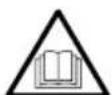
READ THIS MANUAL CAREFULLY BEFORE OPERATION
Failure to follow the instructions and safety precautions in this manual can result in property damage, serious injury and/or death.
SAVE THIS MANUAL FOR FUTURE REFERENCE

text_image
SIMPSON®LAVEUR SOUS PRESSION À EAU CHAUDE
GUIDE D'UTILISATION ET D'ENTRETIEN
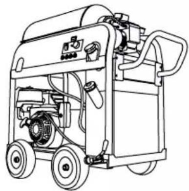
natural_image
Line drawing of a portable industrial machine with wheels and control panel (no text or symbols)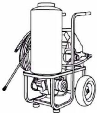
natural_image
Line drawing of a mechanical pressure pump with hoses and wheels (no text or symbols)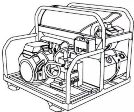
natural_image
Technical line drawing of a mechanical device with internal components and mounting brackets (no text or symbols)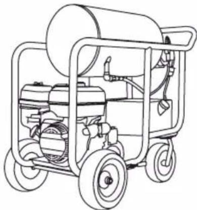
natural_image
Line drawing of a portable water purifier with wheels and equipment (no text or symbols)
REGARDEZ AVANT DE POMPER!
Hoses may pose a tripping hazard that can cause injuries resulting from a fall.

RISQUES DE GLISSEMENT ET DE TRÉBUTS
text_image
CAUTION Watch your step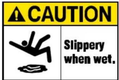
text_image
CAUTION Slippery when wet.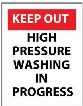
text_image
KEEP OUT HIGH PRESSURE WASHING IN PROGRESS
text_image
CAUTION SLIPPERY WHEN WETnatural_image
Illustration of a blue worker standing on an orange-and-white striped barrier with a yellow coin in the top (no text or symbols)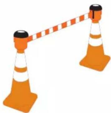
natural_image
Illustration of two orange traffic cones with white stripes and black caps, connected by a dashed orange bar (no text or symbols)
AVERTISSEMENT DE LA PROPOSITION 65 DE LA CALIFORNIE
text_image
Warning symbol with exclamation mark inside triangle, commonly used for safety alertstext_image
Diagram showing the assembly of a spray gun with spring-loaded components and an adjustable wrench, illustrating mechanical assembly steps.natural_image
Line drawing of a mechanical device with wheels and a tool, no text or symbols present
natural_image
Line drawing of a device panel with buttons and a paint bucket, no text or symbols presentnatural_image
Diagram of a mechanical component with a meshed circular feature and an arrow pointing to a threaded hole (no text or symbols)natural_image
Diagram of a connector with threaded ends and a hexagonal nut inserted (no text or symbols)natural_image
Diagram showing a pipe fitting process: before and after transformation (no text or symbols)natural_image
Line drawing of a mechanical device with a connector, showing a directional arrow pointing to its component (no text or symbols present)IMPORTANT!
natural_image
Diagram of a solenoid with magnetic field lines and an arrow indicating direction (no text or labels)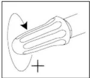
natural_image
Simple line drawing of a bulb-like object with an arrow indicating rotation, no text or symbols present.AVISAVI
PROCÉDEZ AU RÉGLAGE AVEC PRÉCAUTION
natural_image
Illustration of two hands holding small mechanical components, one pointing to a black component (no text or symbols present)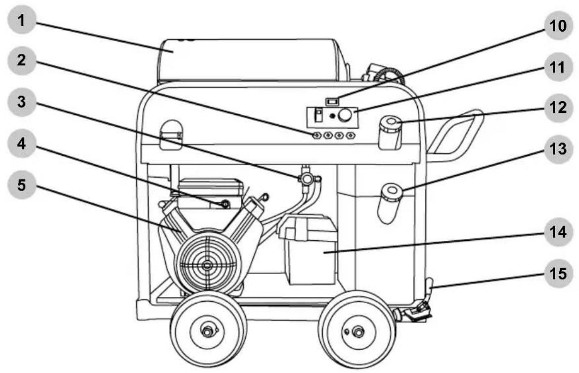
text_image
1 2 3 4 5 10 11 12 13 14 15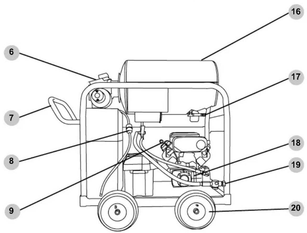
text_image
Technical diagram of a portable electric pump with numbered components labeled for identification.LAVEUR SOUS PRESSION À MOTEUR
text_image
Technical diagram of a mechanical device with numbered parts for identification and assembly reference.LAVEUR SOUS PRESSION À MOTEUR, MONTÉ SUR PATINS
text_image
Technical diagram of a fire extinguisher with numbered parts for identificationnatural_image
Illustration of two hands holding a small object with an arrow pointing to it (no text or symbols present)natural_image
Simple line drawing of a 3D rectangular shape with no text or symbolsnatural_image
Simple line drawing of a rounded rectangular shape with a central horizontal line (no text or symbols)natural_image
Simple line drawing of a geometric shape resembling a folded paper or polygon (no text or symbols)natural_image
Simple line drawing of a device with two ports and two cables, no text or symbols presentnatural_image
Line drawing of a spray gun with a handle and nozzle (no text or symbols)Emplacement
natural_image
Simple line drawing of a folded paper or envelope shape (no text or symbols)natural_image
Diagram of a mechanical component with a circular end connected to a shaft, showing bidirectional arrow (no text or symbols)natural_image
Diagram showing a connector being inserted into a housing, with no text or symbols present.natural_image
Technical line drawing of a mechanical component with a mesh circular inset and an arrow indicating direction (no text or symbols)ENTRETIEN DU MOTEUR
natural_image
Technical line drawing of a mechanical valve assembly with a gas cylinder and directional arrow (no text or symbols)natural_image
Diagram of a mechanical device with a spray bottle and nozzle, showing no text or symbolsnatural_image
Line drawing of a portable industrial machine with wheels and control panel (no text or symbols)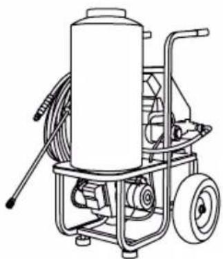
natural_image
Line drawing of a mechanical pressure pump with hoses and wheels (no text or symbols)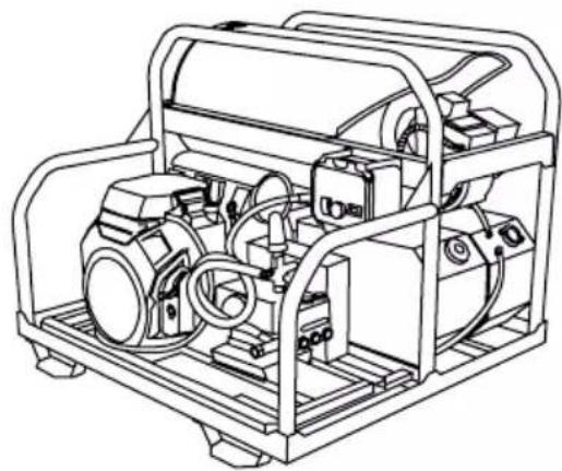
natural_image
Technical line drawing of a mechanical device with internal components (no text or symbols)
natural_image
Line drawing of a portable water purifier with wheels and equipment (no text or symbols)
MIRA ANTES DE BOMBEAR!
Hoses may pose a tripping hazard that can cause injuries resulting from a fall.

PRECAUCION:
PELIGROS DE RESBALÓN / TROPIEZO
text_image
CAUTION Watch your step
text_image
CAUTION Slippery when wet.
text_image
KEEP OUT HIGH PRESSURE WASHING IN PROGRESS
text_image
CAUTION SLIPPERY WHEN WETnatural_image
Illustration of a yellow warning sign on a ladder with orange and white stripes, no text or symbols present
natural_image
Illustration of two orange traffic cones with white stripes and black caps, connected by a diagonal bar (no text or symbols)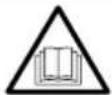
INSTRUCCIONES ADICIONALES
text_image
Diagram showing the assembly of a spray gun with spring-loaded components and an adjustable wrench, illustrating mechanical assembly steps.natural_image
Line drawing of a mechanical device with wheels and a tool, no text or symbols present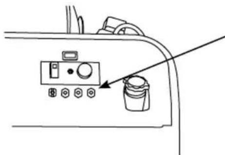
natural_image
Line drawing of a device control panel with buttons and a paint bucket, no text or symbols presentnatural_image
Technical line drawing of a mechanical component with a diagonal line indicating a reference or alignment (no text or symbols present)
natural_image
Technical diagram of a mechanical component with a meshed circular inset and an arrow indicating direction (no text or symbols)natural_image
Technical line drawing of a connector with threaded ends and a hexagonal nut (no text or symbols)natural_image
Diagram showing a pipe fitting being inserted into a connector, with no text or symbols present.natural_image
Line drawing of a mechanical device with a connector inserted, showing no text or symbolsnatural_image
Diagram of a solenoid with magnetic field lines and an arrow indicating direction (no text or labels)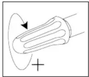
natural_image
Simple line drawing of a bulb with an arrow indicating rotation, no text or symbols presentAVISOAVI
AJUSTE CON CUIDADO
natural_image
Illustration of two hands using a tool to apply material (no text or symbols present)