
TOR24SS - Microwave Oven Thor - Free user manual and instructions
Find the device manual for free TOR24SS Thor in PDF.

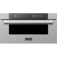
| Product Type | Microwave oven with built-in hood |
| Brand | Thor |
| Model | TOR24SS |
| Width | 61 cm (24 in) |
| Maximum cabinet depth | 38.1 cm (15 in) |
| Approximate height | 43.5 cm (17 1/8 in) |
| Total weight with load | 45.2 to 54.3 kg (100-120 lb) |
| Power supply | 120 V AC, 60 Hz, 15 A (separate branch circuit) |
| Venting modes | Exterior top, exterior rear, recirculation |
| Recommended duct type | Metal, round 15.2 cm (6 in) or rectangular 8.3 x 25.4 cm (3.25 x 10 in) |
| Maximum duct length | 42.7 m (140 ft) equivalent |
| Included filters | 2 grease filters, 1 charcoal filter |
| Grease filter maintenance | Washable |
| Charcoal filter replacement | Every 6 to 12 months depending on use |
| Installation | Under cabinet, requires 2 people, basic electrical and mechanical skills |
| Grounding required | Yes, with three-prong plug |
| Mounting plate dimensions | See manual for precise measurements |
| Number of mounting holes | 3 to 4 depending on studs |
| Included accessories | Mounting plate, vent adapter, filters, screws, wing nuts, toggle bolts, templates |
Frequently Asked Questions - TOR24SS Thor
User questions about TOR24SS Thor
0 question about this device. Answer the ones you know or ask your own.
Ask a new question about this device
Download the instructions for your Microwave Oven in PDF format for free! Find your manual TOR24SS - Thor and take your electronic device back in hand. On this page are published all the documents necessary for the use of your device. TOR24SS by Thor.
USER MANUAL TOR24SS Thor
IMPORTANT SAFETY INSTRUCTIONS
BEFORE YOU BEGIN
Read all instructions thoroughly before installing the Over the Range Microwave Oven.
Note to Installer – Leave these instructions with the consumer.
- Skill level – Installation of this appliance requires basic mechanical and electrical skills. We recommend that two people install this microwave oven.
- Proper installation is the responsibility of the installer.
- Product failure due to improper installation is not covered under the warranty.
- If a new electrical outlet is required, its installation should be completed by a qualified electrician before the Over the Range Microwave Oven is installed. See ELECTRICAL GROUNDING INSTRUCTIONS section.
Note to Consumer – Keep these instructions for future reference.
- Save these instructions for local inspector's use.
- Observe all governing codes and ordinances.
ELECTRICAL GROUNDING INSTRUCTIONS
THIS APPLIANCE MUST BE PROPERLY GROUNDED TO AVOID SEVERE OR FATAL SHOCK. PLEASE READ CAREFULLY.
This appliance must be grounded. This oven is equipped with a cord having a grounding wire with a grounding plug. It must be plugged into a wall receptacle that is properly installed and grounded in accordance with the National Electrical Code and local codes and ordinances. In the event of an electrical short circuit, grounding reduces risk of electric shock by providing an escape wire for the electric current.
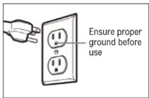
WARNING Improper use of the grounding plug can result in risk of electric shock.
The oven is equipped with a 3-prong grounding plug. NEVER cut or remove the grounding pin from the plug.
The Power Supply Cord and plug must be connected to a separate 120 Volt AC, 60 Hz, 15 Amp, or more branch circuit, si grounded receptacle. The receptacle should be located inside the cabinet directly above the Microwave Oven/Hood mounting location.
Note: If you have any questions about the grounding or electrical instructions, consult a qualified electrician or serviceperson. Neither THOR nor the dealer can accept any liability for damage to the oven or personal injury resulting from failure to observe the correct electrical connection procedures.
CAUTION FOR PERSONAL SAFETY
- Remove the house fuse or open the circuit breaker before beginning installation to avoid severe or fatal shock injury.
- The mounting surface must be capable of supporting the cabinet load, in addition to the added weight of this 50-70 lb (22.6-31.7 kg) product, plus additional oven loads of up to 50 pounds (22.6 kg) for a total weight of 100-120 lb (45.2-54.3 kg).
- This product cannot be installed in cabinet arrangements such as an island or a peninsula. It must be mounted to BOTH a top cabinet AND a wall.
- For easier installation and personal safety, we recommend that two people install this microwave oven.
GENERAL INFORMATION
HOOD EXHAUST
Note: Read the next two pages only if you plan to vent your exhaust to the outside. If you plan to recirculate the air back into the room, proceed to page 6.
All ductwork must be metal. DO NOT use plastic duct. Check that all connections are made securely.
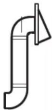
OUTSIDE TOP EXHAUST (EXAMPLE ONLY)
The following chart describes an example of one possible ductwork installation.
 | DUCT PIECES | EQUIVALENT LENGTH X NUMBER USED | EQUIVALENT LENGTH |
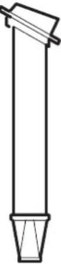
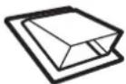 Roof Cap Roof Cap | 24 ft (7.3 m) x 1 | 24 ft (7.3 m) | |
| 12 ft. Straight Duct (6" Round) | 12 ft (3.7 m) x 1 | 12 ft (3.7 m) | |
 Rectangular-to-Round Transition Adapter* Rectangular-to-Round Transition Adapter* | 5 ft (1.5 m) x 1 | 5 ft (1.5 m) | |
| Total Length | 41 ft (12.5 m) | ||
| Equivalent lengths of duct pieces are based on actual tests and reflect requirement for good venting performance with any vent hood. | |||
OUTSIDE REAR EXHAUST (EXAMPLE ONLY)
The following chart describes an example of one possible ductwork installation.
 | DUCT PIECES | EQUIVALENT LENGTH X NUMBER USED | EQUIVALENT LENGTH |
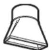
 Wall Cap Wall Cap | 40 ft (12.2 m) x 1 | 40 ft (12.2 m) | |
| [γ224]3 Ft. Straight Duct (31⁄4" x 6" Round) | 3 ft (91.4 cm) x 1 | 3 ft (91.4 cm) | |
| [ccxx]90° Elbow | 10 ft (4 m) x 2 | 20 ft (6.1 m) | |
| Total Length | 63 ft (19.2 m) | ||
| Equivalent lengths of duct pieces are based on actual tests and reflect requirement for good venting performance with any vent hood. | |||
Note: Rear or horizontal exhaust is to be used. Care should be taken to align the exhaust with the space between the studs or the wall should be prepared at the time it is constructed by leaving enough space between wall studs to accommodate exhaust.
*IMPORTANT: If a rectangular-to-round transition adapter is used, the bottom corners of the damper will have to be cut to fit, using the tin snips, in order to allow free movement of the damper.
GENERAL INFORMATION
If you need to install ducts, note that the total duct length of 3/4" x 10" (8.3 x 25.4 cm) rectangular or 6" (15.2 cm) diameter round duct should not exceed 140 equivalent feet (42.7 m).
Outside ventilation requires a HOOD EXHAUST DUCT. Read the following carefully.
It is important that venting be installed using the most direct route and with as few elbows as possible. This ensures clear venting of exhaust and helps prevent blockages. Also, make sure dampers swing freely and nothing is blocking the ducts.
EXHAUST CONNECTION
The hood exhaust has been designed to connect with a standard 3^1/4 x 10" (8.3 x 25.4 cm) rectangular duct.
If a round duct is required, a rectangular-to-round transiting adapter must be used. Do not use less than a 6" (15.2 cm) diameter duct.
MAXIMUM DUCT LENGTH
For satisfactory air movement, the total duct length of 3 1/4"x 10" (8.3 x 25.4 cm) rectangular or 6" (15.2 cm) diameter round duct should not exceed 140 equivalent feet.
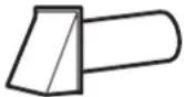
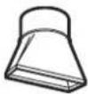
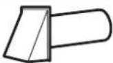
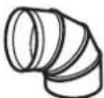
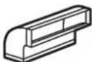
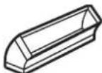
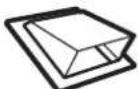
ELBOWS, TRANSITIONS, WALL AND ROOF CAPS, ETC.
Elbows, adapters, wall and roof caps, etc. present additional resistance to air flow and are equivalent to a section of straight duct which is longer than their actual physical size. When calculating the total length, add the equivalent lengths of all transitions and adapters plus the length of all straight duct sections. The chart on the right shows the approximate measurement of equivalent length of some typical ductwork parts.
Use the values in the chart for calculating total ductwork, which should be less than 140 equivalent feet (42.7 m). Equivalent lengths of duct pieces are based on actual tests and reflect requirements for good venting performance with any vent hood.
IMPORTANT: If a rectangular-to-round transition adapter is used, the bottom corners of the damper will have to be cut to fit, using the tin snips, in order to allow free movement of the damper.
| DUCT PIECES | EQUIVALENT LENGTH X NUMBER USED | EQUIVALENT LENGTH |
| EXAMPLE ONLY (VALUES) | ||
 Rectangular-to-Round Transition Adapter Rectangular-to-Round Transition Adapter | 5 ft (1.5 m)x (1) | 5 ft(1.5 m) |
 Wall Cap Wall Cap | 40 ft (12.19 m)x (1) | 40 ft(12.19 m) |
 90° Elbow 90° Elbow | 10 ft (3 m)x (1) | 10 ft(3 m) |
 45° Elbow 45° Elbow | 5 ft (1.5 m)x (1) | 5 ft(1.5 m) |
 90° Elbow 90° Elbow | 25 ft (7.6 m)x (1) | 25 ft(7.6 m) |
 er is 45° Elbow er is 45° Elbow | 5 ft (1.5 m)x (1) | 5 ft(1.5 m) |
 Roof Cap Roof Cap | 24 ft (7.3 m)x (1) | 24 ft(7.3 m) |
| [S4XV]Straight Duct(3 1⁄4" x 6" Round) | 1 ft (30.5 cm)x (5) | 5 ft(1.5 m) |
| Example Total Ductwork | 119 ft (36.3 m) | |
| Example Total Ductwork | 119 ft (36.3 m) |
GENERAL INFORMATION
PARTS INCLUDED
| PART NAME & PART CODE QTY. | ||
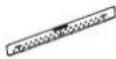 | Mounting Plate9JZ213259000685 | 1 |
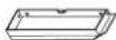 | Exhaust Adapter9JZ213999001159 | 1 |
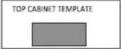 | Top Cabinet Template9JZ525049000030 | 1 |
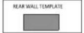 | Rear Wall Template9JZ525049000042 | 1 |
 | Installation InstructionsTINSEB631MRR0 | 1 |
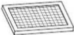
 | Separately Packed Grease Filter9JZ213999001028 | 2 |
 | Charcoal Filter9JZ213999001066 | 1 |
INSTALLATION ACCESSORIES
| PART NAMEPART CODE 9JZ203129000066 | QTY. | |
| Lag Screw (1/4" x 2" / 0.63 x 5.1 cm) 2 | ||
| Wing Nut 2 | ||
| Toggle Bolt (3/16" x 3" / 0.5 x 7.6 cm) | 2 | |
| Cabinet Mounting Bolt(1/4" x 3" / 0.6 x 7.6 cm) | 2 | |
| Nylon Grommet (for metal cabinets) 1 | ||
| Washer 2 | ||
| Sheet Metal Screw 2 | ||
You will find the installation accessories contained in a packet with the unit. Check to make sure you have all these parts.
Note: Some extra parts are included.
TOOLS YOU WILL NEED
 #1 and #2 Phillips screwdrivers #1 and #2 Phillips screwdrivers |  Pencil Ruler or tape measure straight edge Pencil Ruler or tape measure straight edge | 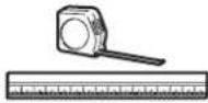 |
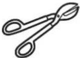 Tin snips (to cut damper, if needed) Tin snips (to cut damper, if needed) | 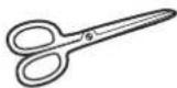 Scissors (to cut template, if needed) Scissors (to cut template, if needed) | 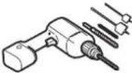 Electric drill with 3/16", 1/2" and 5/8" bits Electric drill with 3/16", 1/2" and 5/8" bits |
 Gloves Safety Gloves Safety |  goggles Duct and masking tape goggles Duct and masking tape |  |
 Saw level (saber, hole, or keyhole) Saw level (saber, hole, or keyhole) |  Carpenter square (optional) Carpenter square (optional) |  Filler blocks or scrap wood pieces (for top cabinet spacing in recessed bottom cabinet installations, if needed) Filler blocks or scrap wood pieces (for top cabinet spacing in recessed bottom cabinet installations, if needed) |
 Level Level | 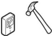 Edge-to-edge stud finder or Hammer (optional) Edge-to-edge stud finder or Hammer (optional) | |
GENERAL INFORMATION
MOUNTING SPACE
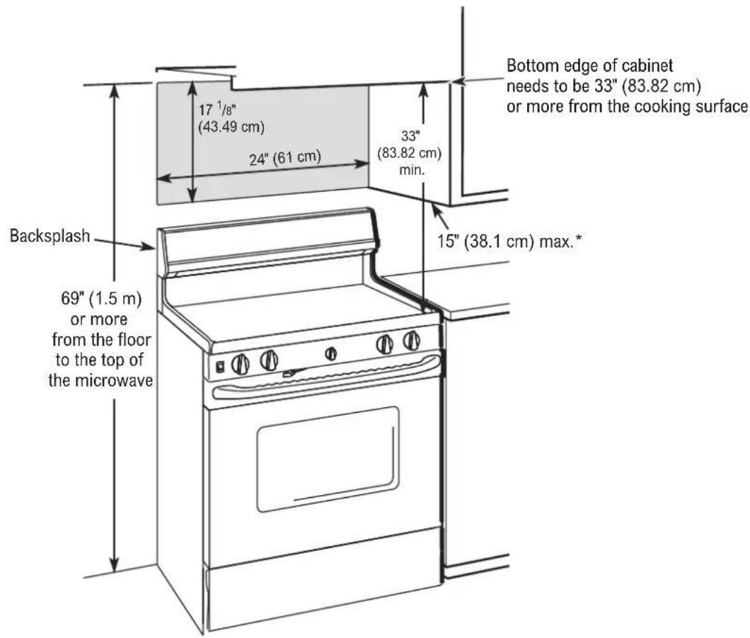
Notes:
- The space between the cabinets must be 24" (61 cm) wide and free of obstructions.
- If you are going to vent your microwave oven to the outside, see Hood Exhaust Section for exhaust duct preparation.
- When installing the microwave oven beneath smooth, flat cabinets, be careful to follow the instruction for power cord clearance. Make sure that you leave enough space for the power cord clearance.
* The maximum depth of the cabinets or wall on either side of the Microwave Oven is 15" (38.1 cm). If the depth is greater than 15" (38.1 cm), the door will not open properly and the door handle opening may not be accessible.
STEP-BY-STEP INSTALLATION GUIDE
PLACEMENT OF THE MOUNTING PLATE
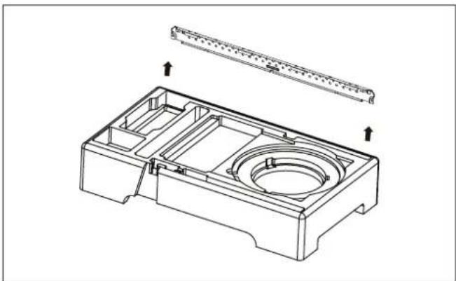
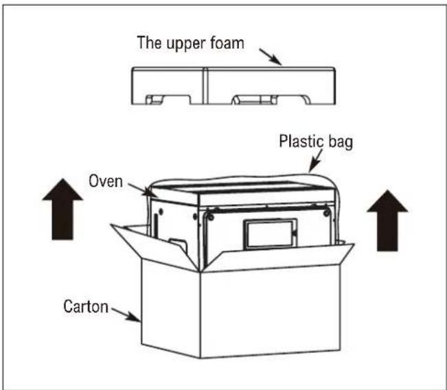
A. REMOVE THE MICROWAVE OVEN AND MOUNTING PLATE FROM CARTON
- Open the carton and remove the upper foam from the box, but remember to keep the accessories.
natural_image
Technical line drawing of a mechanical housing component with internal cavities and mounting brackets (no text or symbols)-
Pull the oven out of the carton and remove the plastic bag carefully.
-
Take the mounting bracket out from the upper foam.
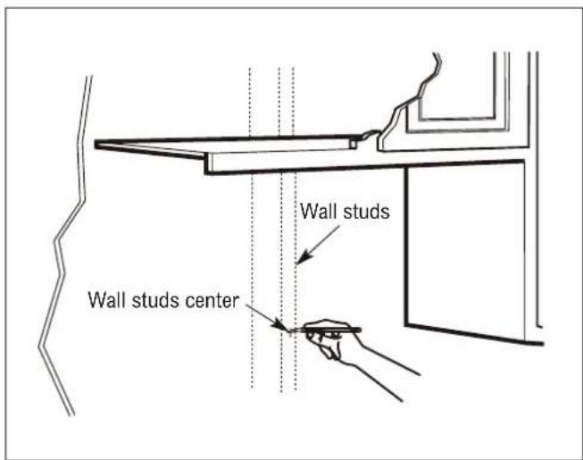
B. FIND THE WALL STUDS
THE MICROWAVE MUST BE MOUNTED TO AT LEAST ONE WALL STUD.
- Find the wall studs using either a wall stud finder (a magnetic device for locating nails) or a hammer to tap lightly across the mounting surface to find a solid sound, which indicates a wall stud location.
-
After locating the stud(s), find the center by probing the wall with a small nail to find the edges of the wall stud.
-
Place a mark halfway between the edges. The center of any adjacent wall studs should be 16" (40.6 cm) or 24" (61 cm) from this mark.
-
Draw a line down the center of the wall studs.
STEP-BY-STEP INSTALLATION GUIDE
C. DETERMINE TOP LINE OF REAR WALL TEMPLATE LOCATION UNDER YOUR CABINET
The bottom of the cabinet has three types:
BENEATH FLAT BOTTOM CABINET
STEP-BY-STEP INSTALLATION GUIDE
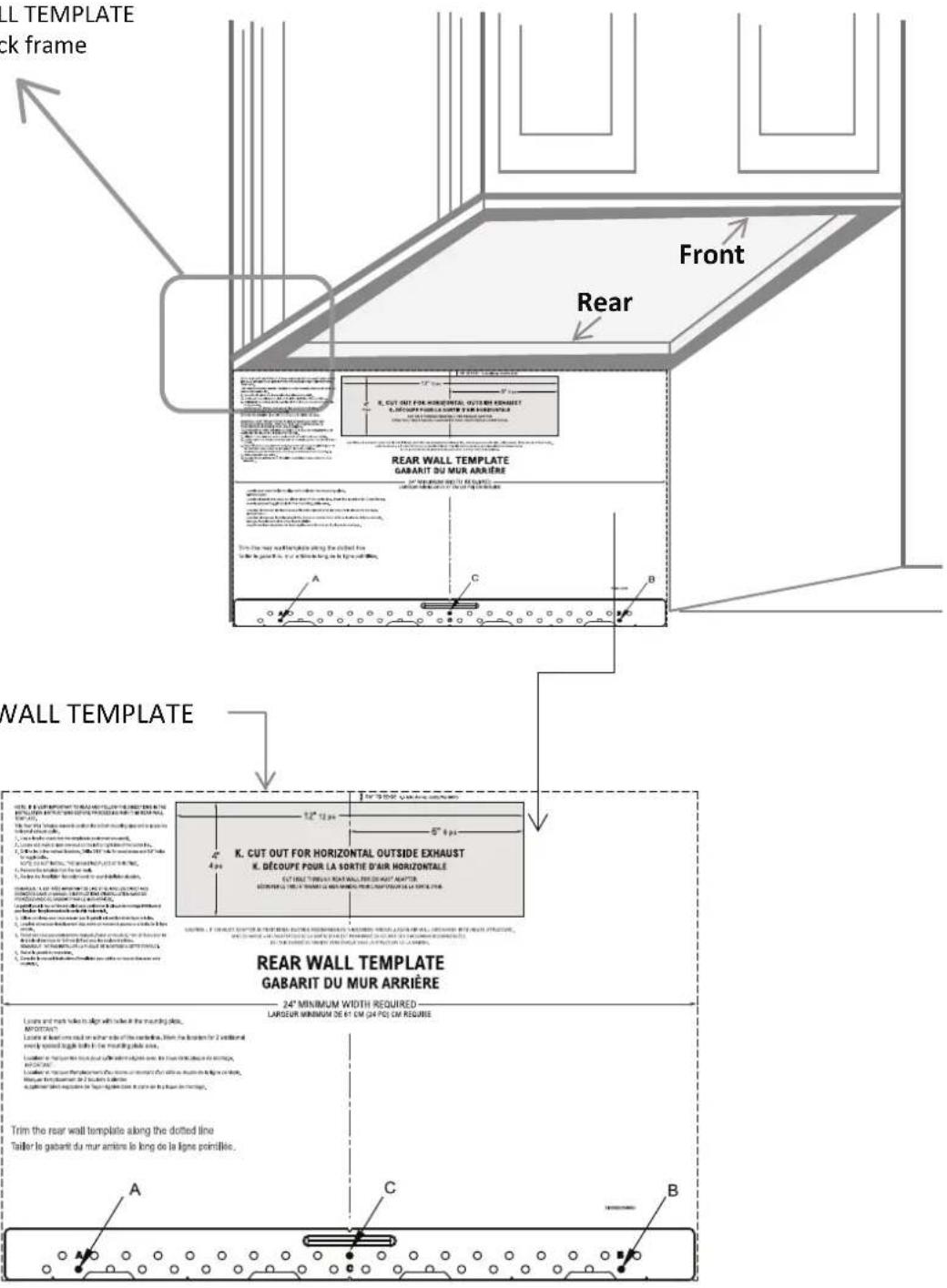
BENEATH FRAMED RECESSED CABINET
TOP LINE OF REAR WALL TEMPLATE
Must align with the back frame
of cabinet bottom
STEP-BY-STEP INSTALLATION GUIDE
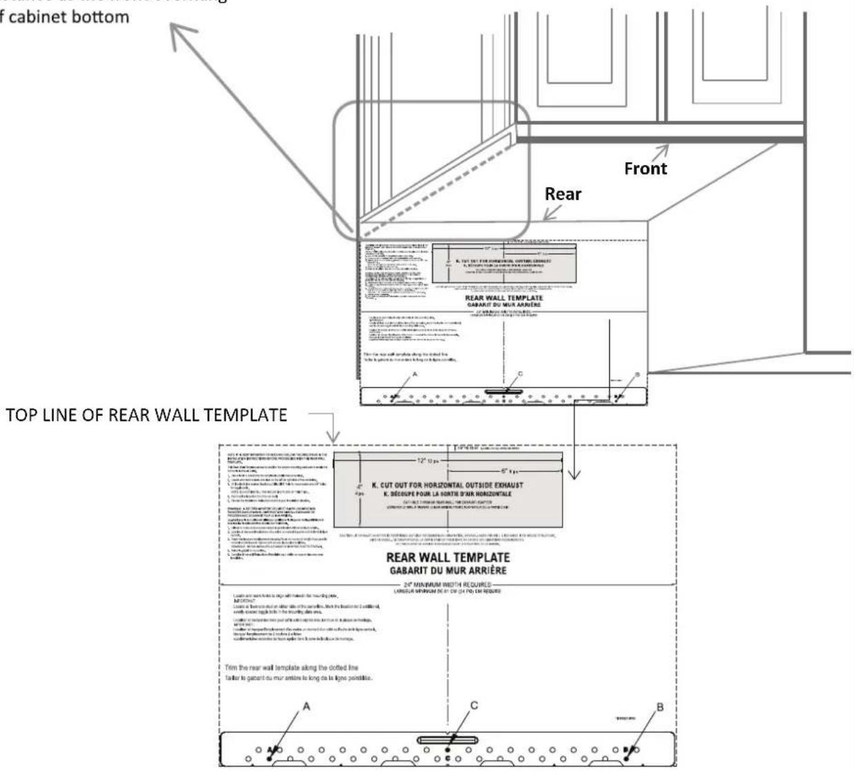
BENEATH FRAMED RECESS BOTTOM CABINET WITH FRONT OVERHANG
TOP LINE OF REAR WALL TEMPLATE
Must align with below cabinet bottom the same distance as the front overhang of cabinet bottom.
Below cabinet bottom the same distance as the front overhang of cabinet bottom
STEP-BY-STEP INSTALLATION GUIDE
Use a level to make sure the cabinet bottom is level. If the cabinets have a front overhang only, with no back or side frame, the top line of Rear Wall Template must align with below cabinet bottom, the same distance as the front overhang depth. This will keep the microwave level.
- Measure the inside depth of the front overhang.
- Draw a horizontal line on the back wall, an equal distance below the cabinet bottom as the inside depth of the front overhang.
- For this type of installation with front overhang only, align top line of Rear Wall Template with this horizontal line, not touching the cabinet bottom as described in step D.
Note: Your cabinets may have decorative trim that interferes with the microwave installation. Remove the decorative trim to install the microwave properly and to make it level.
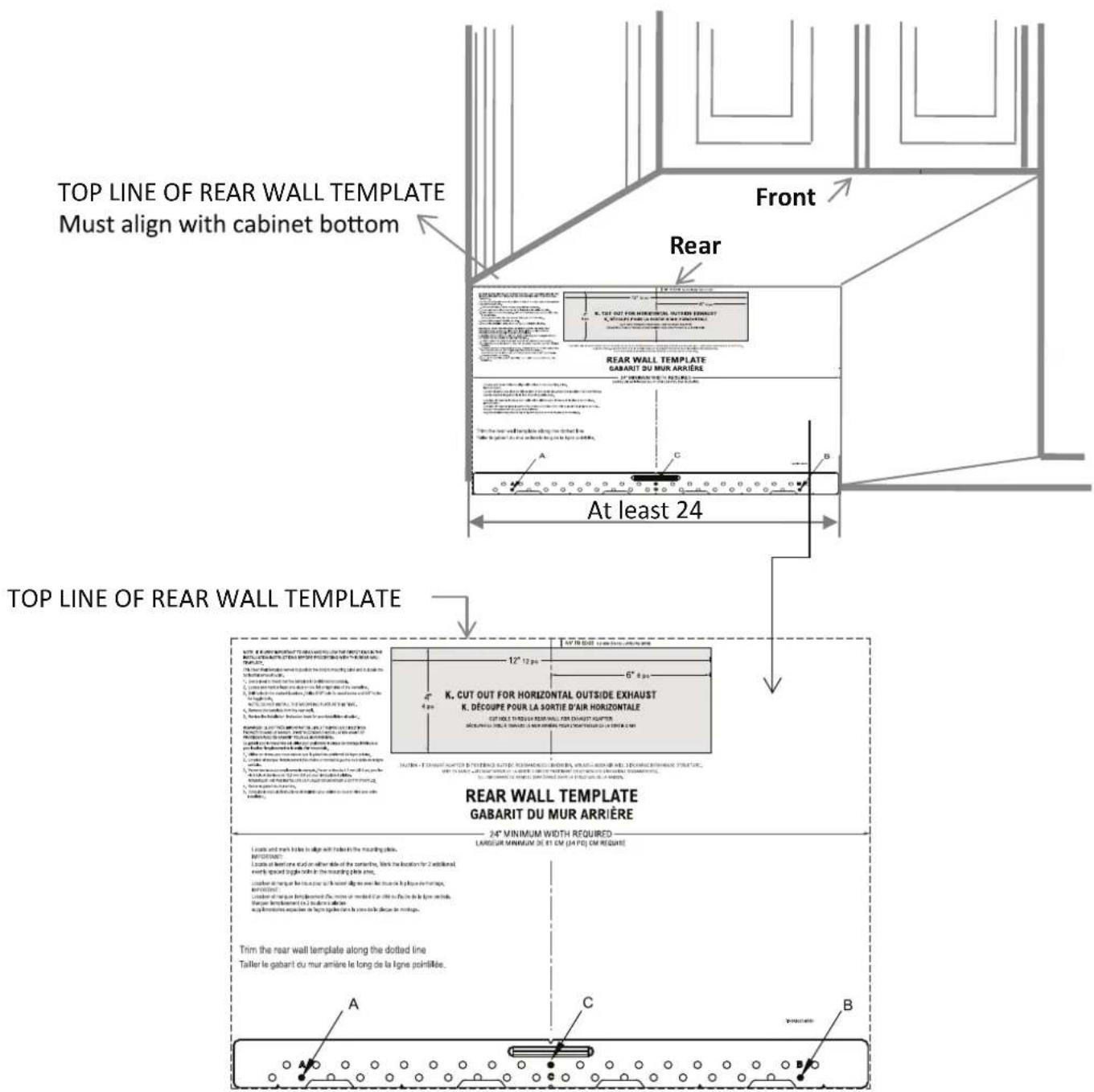
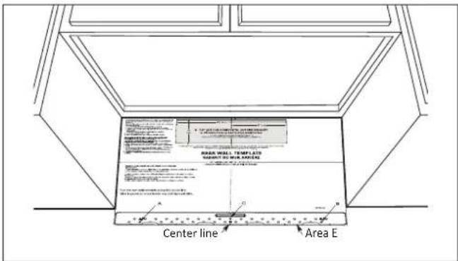
D. ALIGN TOP LINE OF REAR WALL TEMPLATE
⚠️ CAUTION Wear gloves to avoid cutting fingers on sharp edges.
- Using tape measure, draw a vertical line on the wall at the center of the 24" (61 cm) wide space.
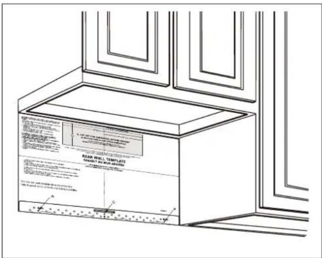
- Tape the Rear Wall Template on the cabinet wall, align the center markers on the Rear Wall Template to the center line on wall, making sure it is level and that the top line of the Rear Wall Template is butted up against the bottom edge of the upper cabinet.
-
While taping the Rear Wall Template on the wall, draw circles on the wall at hole A, B, C (see illustration above/actual plate marked with arrows). THREE HOLES MUST BE USED FOR MOUNTING. (If there are 2 wall studs in right and left side based on center line, four holes must be used for mounting.)
-
Remove the Rear Wall Template and check the marking based on the actual mounting plate (center line, holes A, B, C).
-
Drill holes on the circle marks (A, B, C). Drill a ^3/16 " (4.7 mm) hole at C for lag screw and two ^5/8 " (15.88 mm) holes at A and B for toggle bolts.
Note: DO NOT MOUNT THE PLATE AT THIS TIME.
- If the Rear Wall Template is damaged or unusable, measure and mark the wall with the dimensions described in step E.
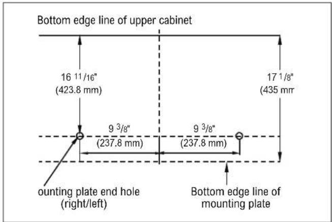
E. MARK REAR WALL OF THE CABINET WITHOUT REAR WALL TEMPLATE
-
The Bottom edge line of Mounting Plate must be 17^1/8 " (435 mm) from the bottom edge line of upper cabinet and must be level.
-
Mounting plate end holes must be 16 "11/16" (423.8 mm) from the bottom edge line of upper cabinet and must be on a equal line with each other. They must each be 93/8" (237.8 mm) from the center line.
INSTALLATION TYPES (CHOOSE A, B OR C)
This microwave oven is designed for adaptation to the following three types of ventilation:
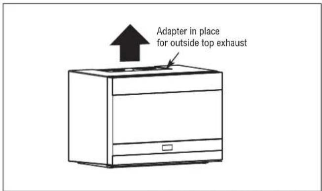
A. OUTSIDE TOP EXHAUST (VERTICAL DUCT)
See page 11.
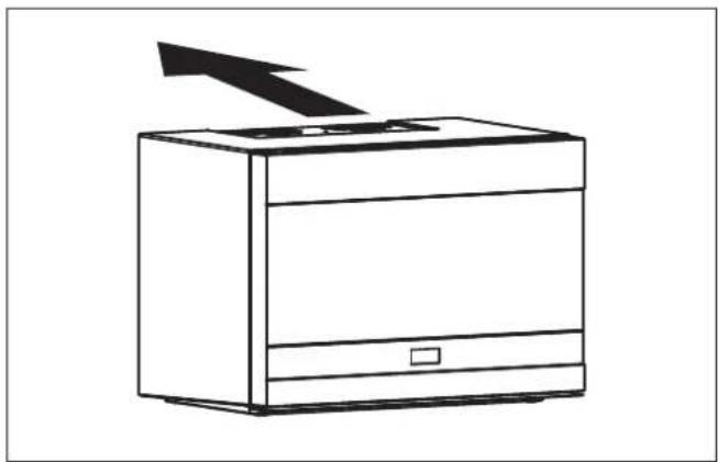
B. OUTSIDE REAR EXHAUST (HORIZONTAL DUCT)
See page 13.
natural_image
Line drawing of a microwave oven with a downward arrow indicating airflow or cooling (no text or symbols)STEP-BY-STEP INSTALLATION GUIDE
C. RECIRCULATING (NON-VENTED DUCTLESS)
See page 17.

natural_image
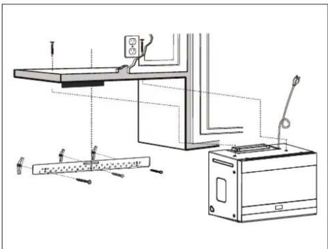
Line drawing of a kitchen appliance with an upward arrow indicating motion (no text or symbols)A. OUTSIDE TOP EXHAUST (VERTICAL DUCT) DEFAULT
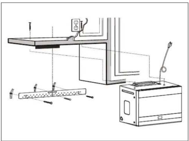
Installation overview
A1. Attach the mounting plate to the wall
A2. Use Top Cabinet Template for preparation of top cabinet
A3. Check for proper damper operation
A4. Mount the microwave oven
A5. Adjust the exhaust adapter
A6. Connect ductwork
natural_image
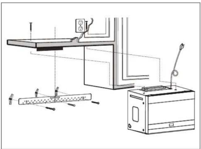
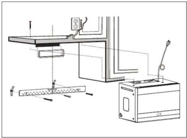
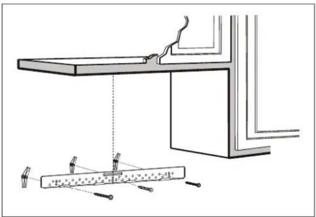
Technical line drawing of a kitchen appliance assembly with tools and components (no text or symbols)A1. ATTACH MOUNTING PLATE TO THE WALL
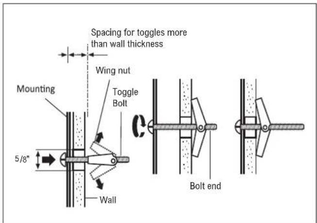
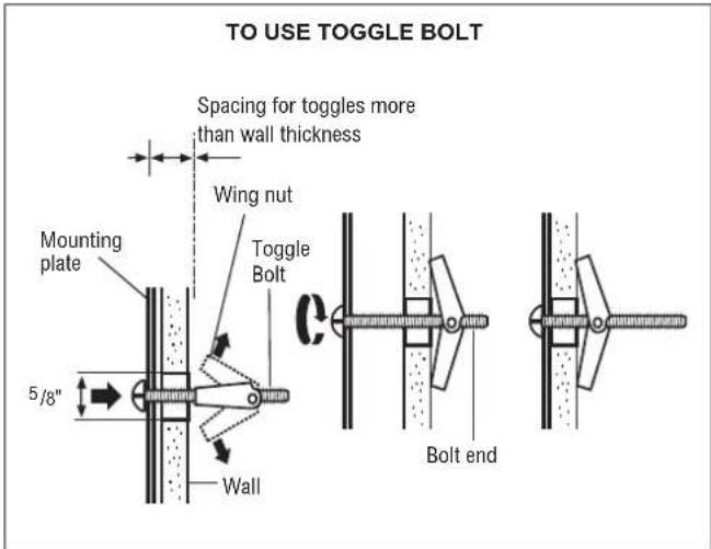
Attach the mounting plate to the wall using the wing nuts and toggle bolts ( ^3/_16 " x 3" / 0.5 x 7.6 cm). At least one lag screw must be used to attach the mounting plate to a wall stud.
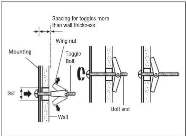
- Insert the toggle bolts ( ^3/16 " x 3" / 0.5 x 7.6 cm) into the mounting plate through the holes designed to go into drywall and attach the wing nuts to ^3/4 " (1.9 cm) onto each toggle bolt ( ^3/_16 " x 3" / 0.5 x 7.6 cm).
- Place the mounting plate against the wall and insert the wing nuts into the holes in the wall to mount the plate.
CAUTION Be careful to avoid pinching fingers between the back of the mounting plate and the wall.
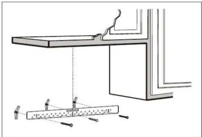
natural_image
Technical line drawing of a structural support system with beams and rods, no text or symbols present- Tighten all bolts. Pull the mounting plate away from the wall to help tighten the bolts.
STEP-BY-STEP INSTALLATION GUIDE
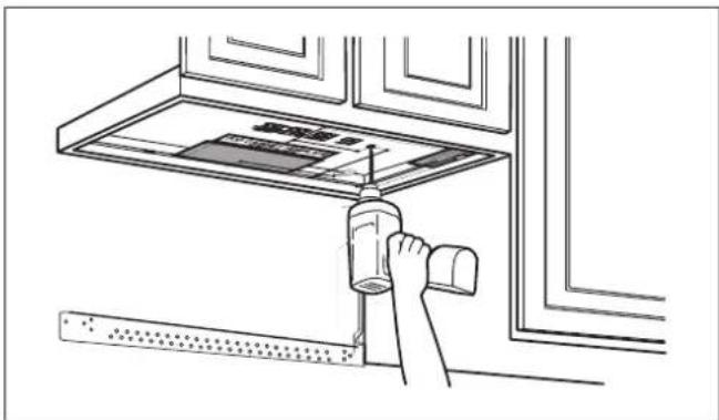
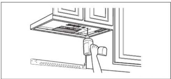
A2. USE TOP CABINET TEMPLATE FOR PREPARATION OF TOP CABINET
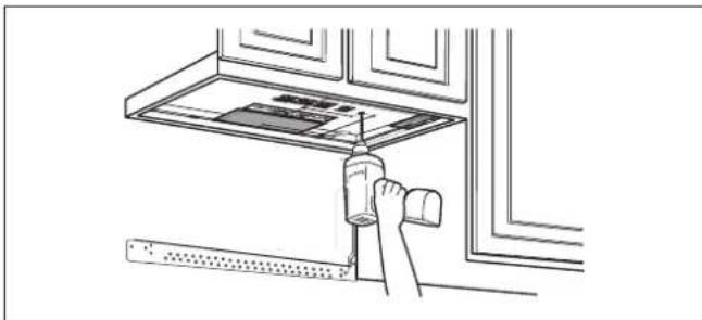
Drill holes for the top support screws, a hole large enough for the power cord to fit through and a cutout large enough for the exhaust adapter.
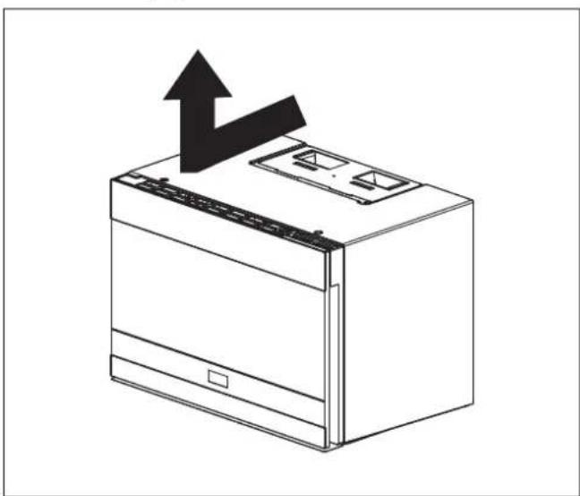
natural_image
Line drawing of a hand using a tool to lift a wall-mounted device (no text or symbols visible)- Read the instructions on the Top Cabinet Template.
- Tape the template underneath the top cabinet bottom.
- Drill the holes, following the instructions on the Top Cabinet Template.
CAUTION Wear safety goggles when drilling holes in the cabinet bottom.
- Place the microwave in its upright position with the top of the unit facing up.
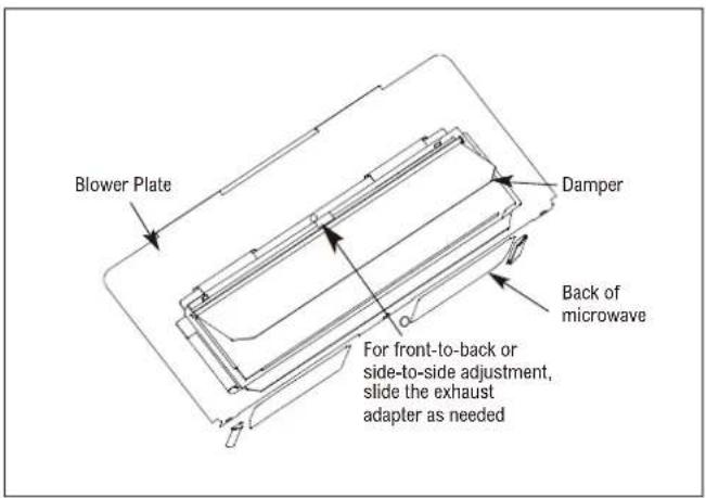
- The exhaust adapter is only used for top exhaust and rear outside exhaust. The exhaust adapter is not used on models vented for recirculation exhaust.
- Make sure tape securing damper is removed and damper pivots easily before mounting microwave.
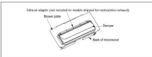
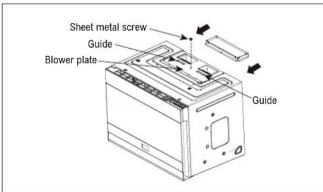
- Attach the exhaust adapter to the blower plate by sliding it into the guides. Secure the adapter with one Sheet Metal Screw provided.
- You will need to make adjustment to ensure proper alignment with your house exhaust duct after the microwave is installed.
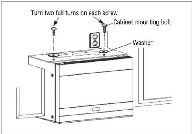
A4. MOUNT THE MICROWAVE OVEN
FOR EASIER INSTALLATION AND PERSONAL SAFETY, WE RECOMMEND THAT TWO PEOPLE INSTALL THIS MICROWAVE OVEN.
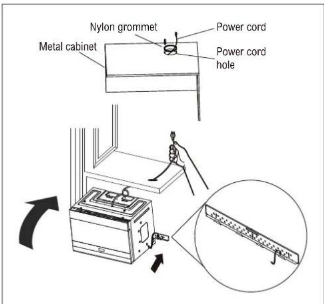
IMPORTANT: Do not grip or use handle during installation. If filler blocks are not used, outer case damage may occur from over tightening screws.
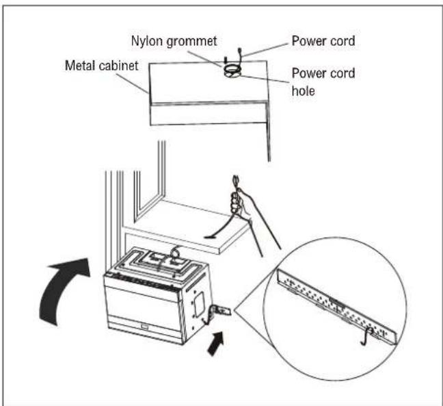
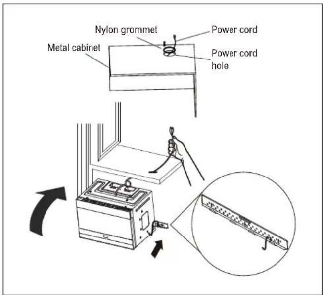
Note: If your cabinet is metal, use the nylon grommet around the power cord hole to prevent cutting of the cord. We recommend using filler blocks if the cabinet front hangs below the cabinet bottom shelf.
When mounting the microwave oven, thread power cord through hole in bottom of top cabinet. Keep it tight throughout steps 1-4. Do not pinch cord or lift oven by pulling cord.
- Lift microwave, tilt it forward and hook slots at back bottom edge onto four lower tabs of mounting plate.
- Rotate front of oven up against cabinet bottom.
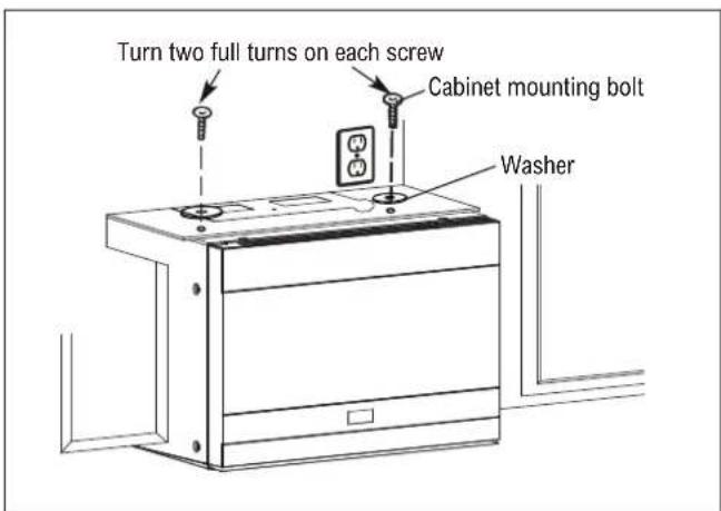
- Attach the microwave oven to the top cabinet.
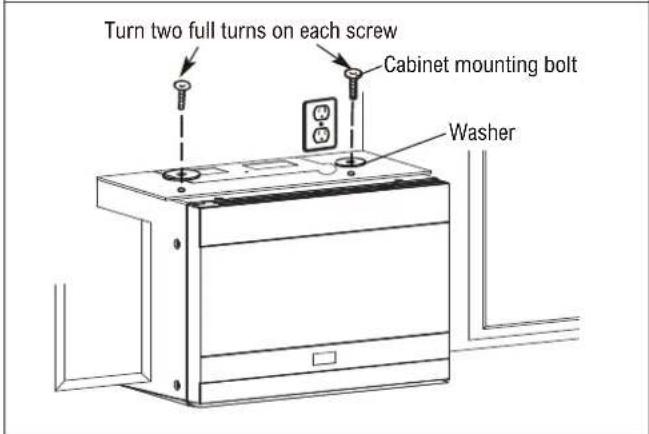
- Insert two cabinet mounting bolts (1/4" x 3" / 0.6 x 7.6 cm) through outer top cabinet holes. Temporarily secure the oven by turning the screw at least two full turns after the threads have engaged. (It will be completely tightened later.) Be sure to keep power cord tight. Be careful not to pinch the cord, especially when mounting flush to the bottom of cabinet.
STEP-BY-STEP INSTALLATION GUIDE
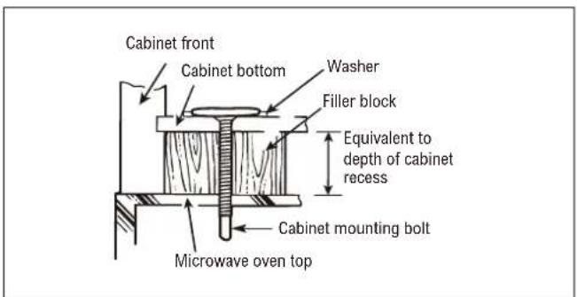
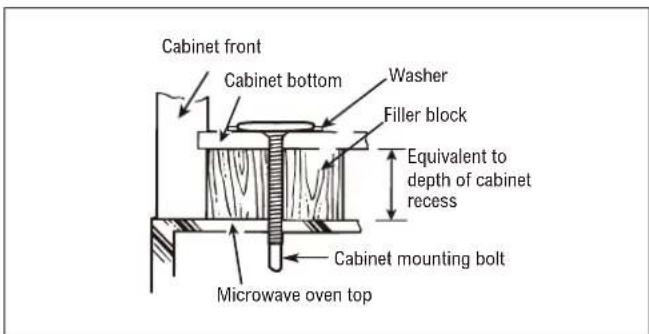
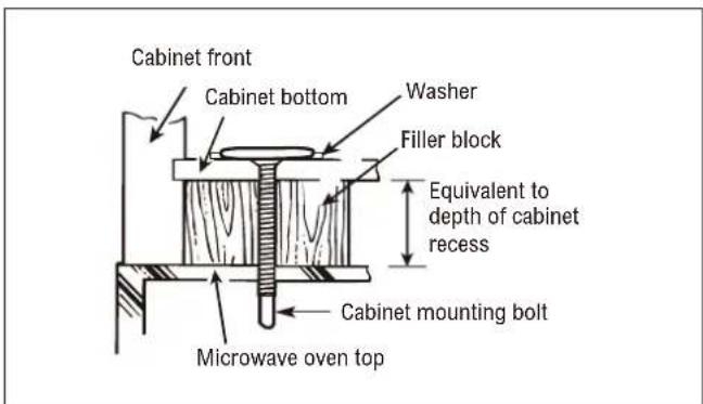
The Filler Block is only used for recessed cabinet and front overhang cabinet (see the type of the cabinet on page 8 - 9). Place the Filler Block to the cabinet bottom before installing the oven.
- Tighten the outer two screws to the top of the microwave oven. While tightening screws, hold the microwave oven in place against the wall and the top cabinet.
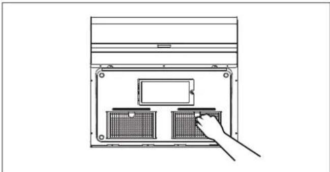
- Install grease filters. See the Operation Manual packed with the microwave.
natural_image
Line drawing of a computer tower with an open panel and a hand inserting a button (no text or symbols)A5. ADJUST THE EXHAUST ADAPTER
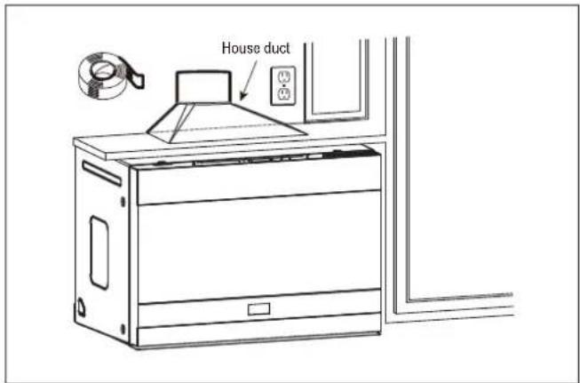
Open the top cabinet and adjust the exhaust adapter to connect to the house duct.
A6. CONNECT DUCTWORK
- Extend the house duct down to connect to the exhaust adapter.
- Seal exhaust duct joints using duct tape.
B. OUTSIDE REAR EXHAUST (HORIZONTAL DUCT)
Installation overview
B1. Prepare the Rear Wall Template for outside back exhaust.
B2. Attach the mounting plate to the wall.
B3. Use Top Cabinet Template for preparation of top cabinet.
B4. Adapt microwave blower for outside back exhaust.
B5. Mount the microwave oven.
natural_image
Technical line drawing of a kitchen appliance assembly with labeled components (no text or symbols)STEP-BY-STEP INSTALLATION GUIDE
B1. PREPARE THE REAR WALL TEMPLATE FOR OUTSIDE BACK EXHAUST
You need to cut an opening (12" x 4" / 30.5 x 10.2 cm rectangular hole) in the Rear Wall Template for outside exhaust.
- Read the instructions on the Rear Wall Template.
- Tape it to the rear wall, lining up with the holes previously drilled for holes A and B in the wall plate.
- Cut the opening, following the instructions of the Rear Wall Template.
B2. ATTACH MOUNTING PLATE TO THE WALL
Attach the mounting plate to the wall using the wing nuts and toggle bolts ( ^3/_16 " x 3" / 0.5 x 7.6 cm). At least one lag screw must be used to attach the mounting plate to a wall stud.
- Insert the toggle bolts ( ^3/16 " x 3" / 0.5 x 7.6 cm) into the mounting plate through the holes designed to go into drywall and attach the wing nuts to ^3/4 " (1.9 cm) onto each toggle bolt ( ^3/_16 " x 3" / 0.5 x 7.6 cm).
natural_image
Technical line drawing of a kitchen appliance assembly with no visible text or symbols- Place the mounting plate against the wall and insert the wing nuts into the holes in the wall to mount the plate.
CAUTION Be careful to avoid pinching fingers between the back of the mounting plate and the wall.
- Tighten all bolts. Pull the mounting plate away from the wall to help tighten the bolts.
B3. USE TOP CABINET TEMPLATE FOR PREPARATION OF TOP CABINET
You need to drill holes for the top support screws and a hole large enough for the power cord to fit through.
- Read the instructions on the Top Cabinet Template.
- Tape it underneath the top cabinet bottom.
- Drill the holes, following the instructions on the Top Cabinet Template.
CAUTION Wear safety goggles when drilling holes in the cabinet bottom.
STEP-BY-STEP INSTALLATION GUIDE
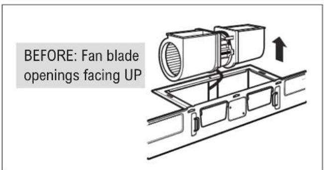
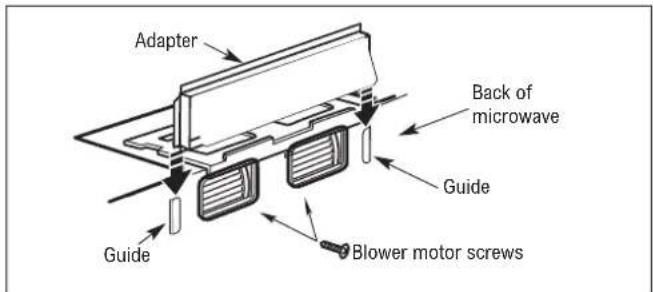
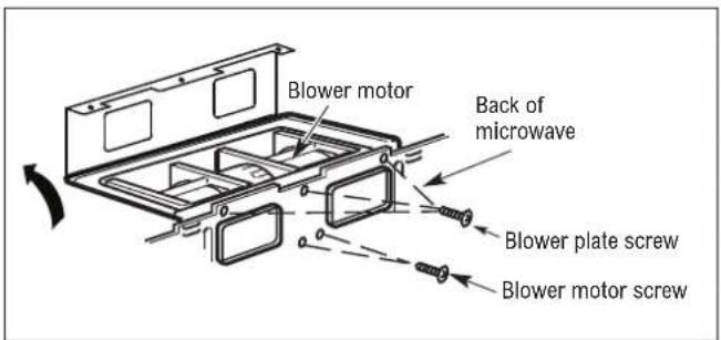
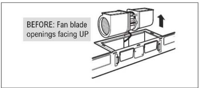
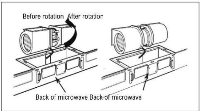
B4. ADAPT MICROWAVE BLOWER FOR OUTSIDE REAR EXHAUST
- Remove and save screw that holds blower motor to microwave. Lift up the blower plate.
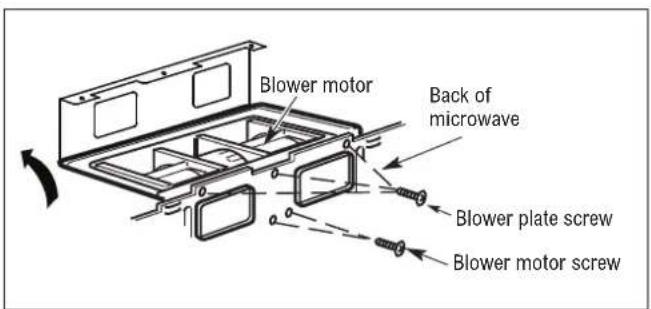
- Carefully pull out the blower unit. The wires will extend far enough to allow you to adjust the blower unit.
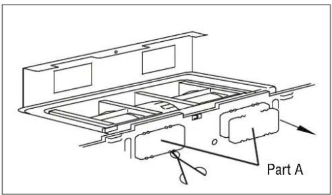
- Remove Parts A with tin snips.
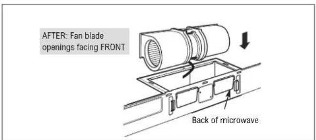
- Rotate blower unit counterclockwise 90^ .
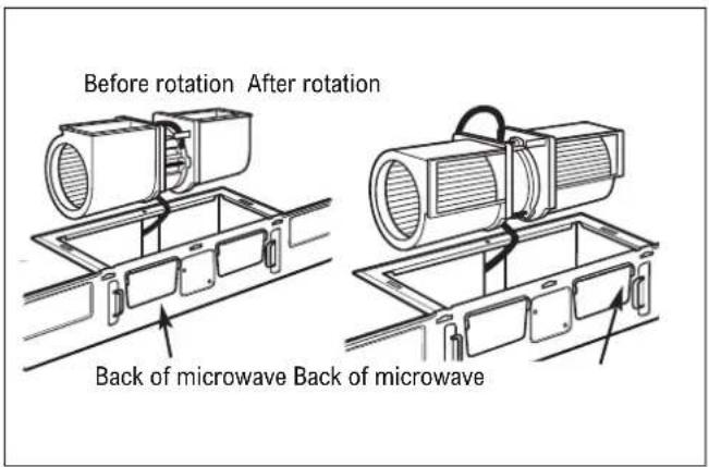
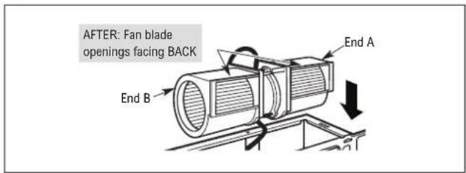
- Place the blower unit back into the opening.
⚠️ CAUTION Do not pull or stretch the blower unit wiring. Make sure the wires are not pinched.
Note: The blower unit exhaust openings should match exhaust openings on rear of microwave oven.
-
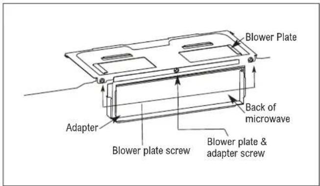
Replace the blower plate in the same position.
-
Attach the exhaust adapter to the rear of the oven by sliding it into the guides at the top center of the back of the oven.
Push in securely until it is in the lower blower motor screw. Take care to assure that the damper hinge is installed so that it is at the top and that the damper swings freely.
- Secure the blower motor unit to the microwave with screws as before.
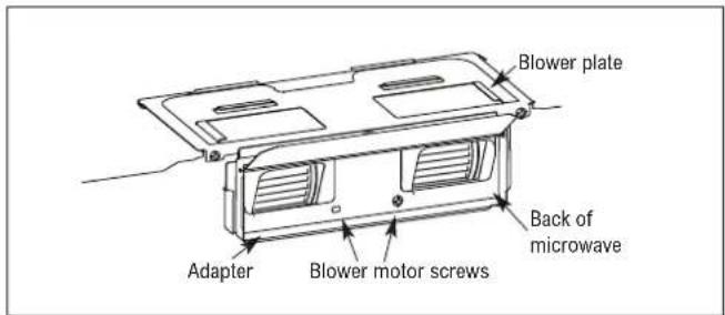
- Secure the blower plate to the microwave with screws. Replace the blower plate in the same position.
STEP-BY-STEP INSTALLATION GUIDE
IMPORTANT: Do not grip or use handle during installation. If filler blocks are not used, outer case damage may occur from over tightening screws.
Note: If your cabinet is metal, use the nylon grommet around the power cord hole to prevent cutting of the cord. We recommend using filler blocks if the cabinet front hangs below the cabinet bottom shelf.
When mounting the microwave oven, thread power cord through hole in bottom of top cabinet. Keep it tight throughout steps 1 - 4. Do not pinch cord or lift oven by pulling cord.
- Lift microwave, tilt it forward and hook slots at back bottom edge onto four lower tabs of mounting plate.
- Rotate front of oven up against cabinet bottom.
- Attach the microwave oven to the top cabinet.
- Insert two cabinet mounting bolts (1/4" x 3" / 0.6 x 7.6 cm) through outer top cabinet holes. Temporarily secure the oven by turning the screw at least two full turns after the threads have engaged. (It will be completely tightened later.) Be sure to keep power cord tight. Be careful not to pinch the cord, especially when mounting flush to the bottom of cabinet.
The Filler Block is only used for recessed cabinet and front overhang cabinet (see the type of the cabinet on pages 8 - 9). Place the Filler Block to the cabinet bottom before installing the oven.
- Tighten the outer two screws to the top of the microwave oven. While tightening screws, hold the microwave oven in place against the wall and the top cabinet.
- Install grease filters. See the Operation Manual packed with the microwave.
natural_image
Line drawing of a laptop front panel with two internal compartments and a hand pointing to the screen (no text or symbols)STEP-BY-STEP INSTALLATION GUIDE
C. RECIRCULATING (NON-VENTED DUCTLESS)
Installation overview
C1. Attach the mounting plate to the wall
C2. Use Top Cabinet Template for preparation of top cabinet
C3. Adapt blower for recirculation
C4. Mount the microwave oven
C5. Change the charcoal filter
natural_image
Technical line drawing of a kitchen appliance assembly with tools and components (no text or symbols)C1. ATTACH MOUNTING PLATE TO THE WALL
Attach the mounting plate to the wall using the wing nuts and toggle bolts ( ^3/_16 " x 3" / 0.5 x 7.6 cm). At least one lag screw must be used to attach the mounting plate to a wall stud.
- Insert the toggle bolts ( ^3/16 " x 3" / 0.5 x 7.6 cm) into the mounting plate through the holes designed to go into drywall and attach the wing nuts to ^3/4 " (1.9 cm) onto each toggle bolt ( ^3/_16 " x 3" / 0.5 x 7.6 cm).
- Place the mounting plate against the wall and insert the wing nuts into the holes in the wall to mount the plate.
CAUTION
Be careful to avoid pinching fingers between
the back of the mounting plate and the wall.
natural_image
Technical line drawing of a structural support frame with a ruler and tool, no text or symbols present- Tighten all bolts. Pull the mounting plate away from the wall to help tighten the bolts.
C2. USE TOP CABINET TEMPLATE FOR PREPARATION OF TOP CABINET
You need to drill holes for the top support screws, a hole large enough for the power cord to fit through.
natural_image
Line drawing of a hand using a tool to lift a wall-mounted device (no text or symbols present)- Read the instructions on the Top Cabinet Template.
- Tape the template underneath the top cabinet bottom.
- Drill the holes, following the instructions on the Top Cabinet Template.
CAUTION
Wear safety goggles when drilling holes in the
cabinet bottom.
STEP-BY-STEP INSTALLATION GUIDE
C3. ADAPT BLOWER FOR RECIRCULATION
- Remove and save screw that holds blower motor to microwave. Lift up the blower plate.
- Carefully pull out the blower unit. The wires will extend far enough to allow you to adjust the blower unit.
- Rotate blower unit 90°.
- Place the blower unit back into the opening.
CAUTION Do not pull or stretch the blower unit wiring. Make sure the wires are not pinched.
Note: The blower unit exhaust openings should match exhaust openings on rear of microwave oven.
- Replace the blower plate in the same position.
IMPORTANT: Do not grip or use handle during installation. If filler blocks are not used, case damage may occur from over tightening screws.
Note: If your cabinet is metal, use the nylon grommet around the power cord hole to prevent cutting of the cord. We recommend using filler blocks if the cabinet front hangs below the cabinet bottom shelf.
When mounting the microwave oven, thread power cord through hole in bottom of top cabinet. Keep it tight throughout steps 1 - 4. Do not pinch cord or lift oven by pulling cord.
- Lift microwave, tilt it forward and hook slots at back bottom edge onto four lower tabs of mounting plate.
- Rotate front of oven up against cabinet bottom.
- Attach the microwave oven to the top cabinet.
- Insert two cabinet mounting bolts (1/4" x 3" / 0.6 x 7.6 cm) through outer top cabinet holes. Temporarily secure the oven by turning the screw at least two full turns after the threads have engaged. (It will be completely tightened later.) Be sure to keep power cord tight. Be careful not to pinch the cord, especially when mounting flush to the bottom of cabinet.
STEP-BY-STEP INSTALLATION GUIDE
The Filler Block is only used for recessed cabinet and front overhang cabinet (see the type of the cabinet on pages 8 - 9). Place the Filler Block to the cabinet bottom before installing the oven.
- Tighten the outer two screws to the top of the microwave oven. While tightening screws, hold the microwave oven in place against the wall and the top cabinet.
- Install grease filters. See the Operation Manual included with the microwave.

natural_image
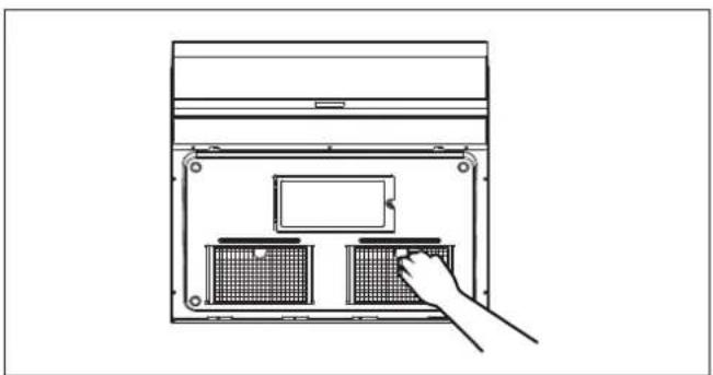
Line drawing of a device interior with two labeled storage units and a hand pointing to one (no text or symbols)C5. CHANGE THE CHARCOAL FILTER
The charcoal filter is used for nonvented, recirculated installation. The filter should be changed every 6 to 12 months depending on use.
- Remove two screws of the louver on the top of the oven by using a #1 Phillips screwdriver.
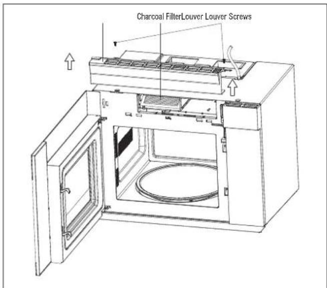
- Open the door, remove the louver and take the used charcoal filter out.
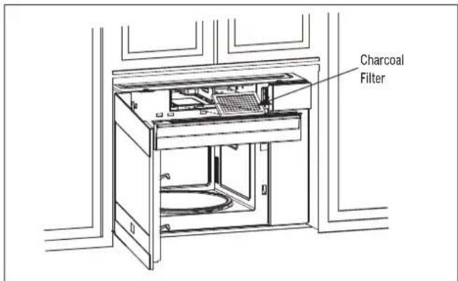
- Install the new charcoal filter. When properly installed, the wire mesh of the filter should be visible from the front.
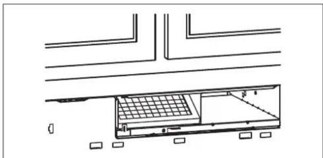
natural_image
Architectural line drawing of a building interior with structural beams and a grid-patterned enclosure (no text or symbols)- Replace the louver and the screws.
CONSIGNES DE SÉCURITÉ IMPORTANTES
AVANT DE COMMENCER
natural_image
Technical line drawing of a mechanical housing assembly with internal components and mounting brackets (no text or symbols)natural_image
Line drawing of a portable air conditioner unit with a black arrow pointing to the top panel (no text or symbols)GUIDE D'INSTALLATION ÉTAPE PAR ÉTAPE
C. RECIRCULATION (NON VENTILÉ, SANS CONDUIT)
Consultez la page 17.
natural_image
Line drawing of a kitchen appliance with an upward arrow indicating motion (no text or symbols)A. SORTIE D'ÉVACUATION EXTÉRIEURE PAR LE HAUT (CONDUIT VERTICAL) PAR DÉFAUT
natural_image
Technical line drawing of a kitchen appliance setup with a microwave oven, standboard, and electrical panel (no text or labels)A1. FIXER LA PLAQUE DE MONTAGE AU MUR
natural_image
Technical line drawing of a structural assembly with beams and supports, no text or symbols presentnatural_image
Line drawing of a hand using a tool to lift a wall-mounted device (no text or symbols visible)natural_image
Line drawing of a computer rack with two fans and a monitor, showing a hand inserting a fan into the rack (no text or symbols)A5. AJUSTER L'ADAPTATEUR D'ÉVACUATION
natural_image
Technical line drawing of a kitchen appliance assembly including a microwave oven, wall-mounted unit, and cleaning tools (no text or labels)B1. PRÉPARER LE GABARIT MURAL ARRIÈRE POUR LA SORTIE D'ÉVACUATION ARRIÈRE À L'EXTÉRIEUR.
natural_image
Technical line drawing of a kitchen appliance assembly with no visible text or symbolsnatural_image
Line drawing of a hand using a tool to clean or install a wall-mounted device (no text or symbols visible)natural_image
Diagram of a computer tower with two grilles and a monitor, showing a hand inserting a component (no text or symbols present)C. RECIRCULATION (NON VENTILÉ, SANS CONDUIT)
natural_image
Technical line drawing of a kitchen appliance assembly with tools and components (no text or symbols)C1. FIXER LA PLAQUE DE MONTAGE AU MUR
natural_image
Technical line drawing of a structural support system with a beam and ruler, no text or symbols presentGUIDE D'INSTALLATION ÉTAPE PAR ÉTAPE
natural_image
Line drawing of a hand using a tool to lift a wall-mounted device (no text or symbols present)natural_image
Line drawing of a computer tower with two internal compartments and a hand pointing to one (no text or symbols)C5. CHANGER LE FILTRE AU CHARBON
natural_image
Architectural line drawing of a building interior with structural beams and a grid-patterned storage unit (no text or symbols)You chose THOR Kitchen to enhance your culinary journey and we're stoked to have you in the club. Think of it as a secret society of really savvy people, such as yourself, choosing professional power and performance at an affordable price.

Register your product by following the steps below.
WARRANTY REGISTRATION

Scan theQR code or visit thorkitchen.com/warranty
Input your product info and select register

You're done. Let's get cookin'.

For additional information and product support, visit thorkitchen.com/service
thorkitchen.com | #COOKLIKEAGOD


- IMPORTANT SAFETY INSTRUCTIONS
- BEFORE YOU BEGIN
- ELECTRICAL GROUNDING INSTRUCTIONS
- CAUTION FOR PERSONAL SAFETY
- GENERAL INFORMATION
- HOOD EXHAUST
- OUTSIDE TOP EXHAUST (EXAMPLE ONLY)
- OUTSIDE REAR EXHAUST (EXAMPLE ONLY)
- EXHAUST CONNECTION
- MAXIMUM DUCT LENGTH
- ELBOWS, TRANSITIONS, WALL AND ROOF CAPS, ETC.
- MOUNTING SPACE
- Notes:
- STEP-BY-STEP INSTALLATION GUIDE
- PLACEMENT OF THE MOUNTING PLATE
- REMOVE THE MICROWAVE OVEN AND MOUNTING PLATE FROM CARTON
- FIND THE WALL STUDS
- THE MICROWAVE MUST BE MOUNTED TO AT LEAST ONE WALL STUD.
- DETERMINE TOP LINE OF REAR WALL TEMPLATE LOCATION UNDER YOUR CABINET
- BENEATH FRAMED RECESS BOTTOM CABINET WITH FRONT OVERHANG
- TOP LINE OF REAR WALL TEMPLATE
- ALIGN TOP LINE OF REAR WALL TEMPLATE
- ⚠️ CAUTION Wear gloves to avoid cutting fingers on sharp edges.
- MARK REAR WALL OF THE CABINET WITHOUT REAR WALL TEMPLATE
- INSTALLATION TYPES (CHOOSE A, B OR C)
- OUTSIDE TOP EXHAUST (VERTICAL DUCT)
- OUTSIDE REAR EXHAUST (HORIZONTAL DUCT)
- RECIRCULATING (NON-VENTED DUCTLESS)
- OUTSIDE TOP EXHAUST (VERTICAL DUCT) DEFAULT
- A1. ATTACH MOUNTING PLATE TO THE WALL
- A2. USE TOP CABINET TEMPLATE FOR PREPARATION OF TOP CABINET
- A4. MOUNT THE MICROWAVE OVEN
- A5. ADJUST THE EXHAUST ADAPTER
- A6. CONNECT DUCTWORK
- B1. PREPARE THE REAR WALL TEMPLATE FOR OUTSIDE BACK EXHAUST
- B2. ATTACH MOUNTING PLATE TO THE WALL
- B3. USE TOP CABINET TEMPLATE FOR PREPARATION OF TOP CABINET
- B4. ADAPT MICROWAVE BLOWER FOR OUTSIDE REAR EXHAUST
- C1. ATTACH MOUNTING PLATE TO THE WALL
- CAUTION
- C2. USE TOP CABINET TEMPLATE FOR PREPARATION OF TOP CABINET
- C3. ADAPT BLOWER FOR RECIRCULATION
- C5. CHANGE THE CHARCOAL FILTER
- CONSIGNES DE SÉCURITÉ IMPORTANTES
- AVANT DE COMMENCER
- GUIDE D'INSTALLATION ÉTAPE PAR ÉTAPE
- RECIRCULATION (NON VENTILÉ, SANS CONDUIT)
- SORTIE D'ÉVACUATION EXTÉRIEURE PAR LE HAUT (CONDUIT VERTICAL) PAR DÉFAUT
- A1. FIXER LA PLAQUE DE MONTAGE AU MUR
- A5. AJUSTER L'ADAPTATEUR D'ÉVACUATION
- B1. PRÉPARER LE GABARIT MURAL ARRIÈRE POUR LA SORTIE D'ÉVACUATION ARRIÈRE À L'EXTÉRIEUR.
- C1. FIXER LA PLAQUE DE MONTAGE AU MUR
- C5. CHANGER LE FILTRE AU CHARBON
- WARRANTY REGISTRATION
Brand : Thor
Model : TOR24SS
Category : Microwave Oven