HP15P004SS - Compressor Hulk Power - Free user manual and instructions
Find the device manual for free HP15P004SS Hulk Power in PDF.

User questions about HP15P004SS Hulk Power
0 question about this device. Answer the ones you know or ask your own.
Ask a new question about this device
Download the instructions for your Compressor in PDF format for free! Find your manual HP15P004SS - Hulk Power and take your electronic device back in hand. On this page are published all the documents necessary for the use of your device. HP15P004SS by Hulk Power.
USER MANUAL HP15P004SS Hulk Power
Operating Instructions
EMAX designs and manufactures products for safe operation. However, operators and maintenance persons are responsible for maintaining safety. All safety precautions are included to provide a guideline for minimizing the possibility of accidents and property damage while equipment is in operation. Keep these instructions for reference.

natural_image
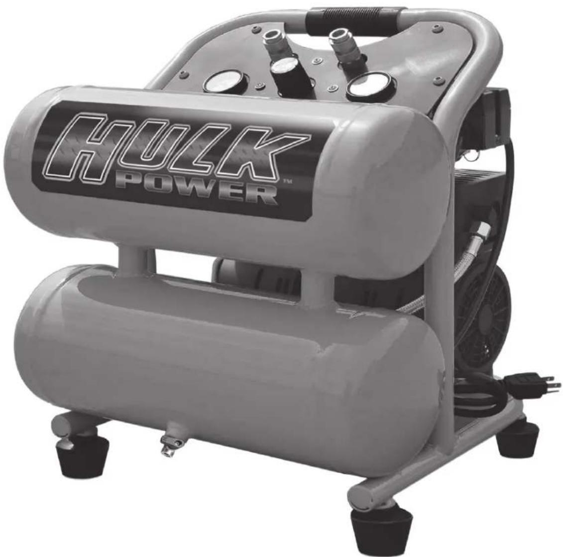
Exterior view of a HULK POWER air compressor unit (no visible text or symbols on the device body)Portable Air Compressor
Model #: HP15P004SS
UPC: 815002013954
Contents
Model Specifications 2
Description 3
Get to know your compressor....3
Safety Information 4
Basic Guidelines 4
Breathable Air 5
Pressurized Components ....5
Personal Protective Equipment....5
Inspection 5
Installation 5
Area 5
Electrical Safety 6
Operation 6
Safety Rules 6
Air Tool Cautions 7
Power Source Connection 8
Power Requirements 8
Grounding Instructions 8
Connect to power source 8
Getting Started 8
Assembly 8
Installing the air filter 8
Operation 8
Before operating your air compressor: ...8
General Overview....9
Installation and Location 9
Connecting to Power Source 9
Extension Cords 9
Attaching an air hose 9
Drain Valve....9
Pressure Switch 10
Adjusting the air pressure 10
Shutting off your compressor....10
Cold Weather Starting....10
Maintenance 10
Daily 10
Monthly 10
Storage....10
Troubleshooting 11
Parts List 12
Schematic Drawing 13
Warranty Statement 14
Model Specifications
• Model: HP15P004SS
- Motor: 120V \~ 60Hz, 7A
- Power: 1 HP
• Max. pressure: 120 psi
• No-load speed: 1700 rpm
- Air delivery:
3.9 cfm @ 40 psi
2.7 cfm @ 90 psi
• Tank size: 2 x 2 gal. (7.6 L)
- Noise: 41 dB(A)
• Weight: 49.9 lb. (22.6 kg)
Description
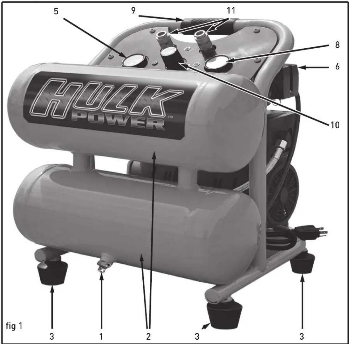
Get to know your compressor
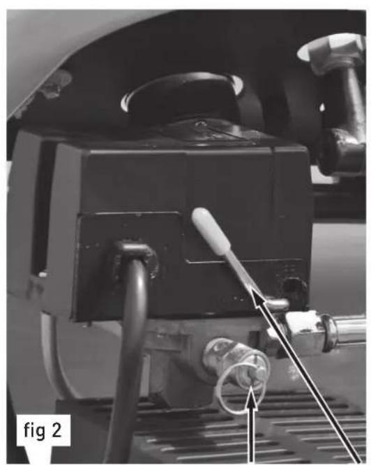
Please refer to fig 1 and 2.
- TANK DRAIN VALVE
(located on bottom of tank) - The tank drain valve can be opened to allow moisture and compressed air to be released from the air tank.
▲WARNING
The tank drain valve should always be opened slowly to
avoid damage to equipment and possible injury.
- TANK -
six gallon (22.7 liters) tank
- RUBBER FOOT
Reduces compressor vibration and movement.
- SAFETY VALVE -
The safety valve automatically relieves pressure from the air tank in the event of excessive pressure build up. Safety Valve is preset at factory. Do not attempt to make any adjustments to the safety valve. Periodically pull the ring on the safety valve end to check that it is working
properly.
- RESERVOIR AIR PRESSURE GAUGE -
Indicates pressure of compressed air built up in the tank.
- PRESSURE SWITCH -
Controlled by the red tipped power switch lever which turns the air compressor on and off. When switch lever is pulled up, compressor is turned off. When lever is moved down to the "Auto" position, the pressure switch is engaged and will start the compressor pump automatically when tank pressure is below the factory-set minimum. The pressure switch continues to monitor the pressure and turns the pump off when the pressure reaches the factory-set maximum.
NOTICE
Always make sure that the
compressor power switch is in the
OFF position before performing any maintenance or plugging the compressor into a power supply.
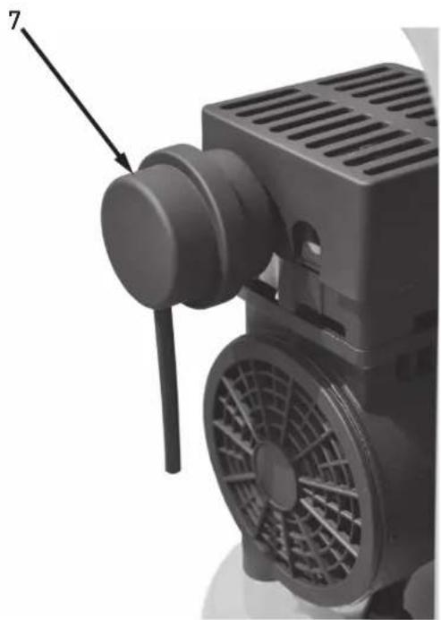
7. AIR FILTER -
Ensures the air being pressurized is free of contaminants and reduces the amount of noise the pump generates.
NOTICE Notice indicates important information, that if not followed, may cause damage to equipment.
natural_image
Close-up of a mechanical device with hoses and a central component, labeled 'fig 2' (no readable text or symbols beyond label)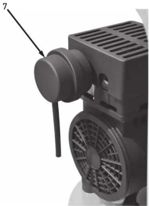
natural_image
Close-up of a black industrial fan or motor with a labeled component (7), showing no visible text or symbols.- OUTPUT AIR PRESSURE GAUGE -
Shows the pressure of the air as it leaves the compressor.
- HANDLE -
Convenient, rubber gripped handle allows for easy transport of your air compressor.
- AIR REGULATOR -
The air regulator controls the output air pressure. Turn regulator clockwise to increase air pressure, counter-clockwise to decrease air pressure.
- AIR COUPLER -
Convenient brass quick-disconnect air coupler allows for fast easy connection to an air hose.
Safety Information
This manual contains very important information to know and understand. This is provided for SAFETY and to PREVENT EQUIPMENT PROBLEMS. To help understand this information, observe the following:
DANGER
Danger indicates an imminently
hazardous situation which, if not cult in death or serious injury.
▲WARNING
Warning indicates a potentially
Hazardous situation which, if not avoided, could result in death or serious injury.
CAUTION
Caution indicates a potentially
avoided, may result in minor or moderate injury.
Read all manuals included with this product carefully. Be thoroughly familiar with the controls and the proper use of the equipment
CALIFORNIA PROPOSITION 65
▲WARNING
This product or its power cord may contain chemicals known to
the State of California to cause cancer and birth defects or other reproductive harm. Wash hands after handling.
Basic Guidelines
- Allow only trained, authorized persons who have read and understood these operating instructions to use this compressor. Failure to follow the instructions, procedures and safety precautions in this manual can result in accidents and injuries.
- NEVER start or operate the compressor under unsafe conditions. Tag the compressor, disconnect and lock out all power to it to prevent accidental start-up until the condition is corrected.
-
Install, use and operate the compressor only in full compliance with all pertinent OSHA regulations and all applicable Federal, State & Local Codes, standards and regulations.
-
NEVER modify the compressor and/or controls in any way.
- Keep a first aid kit in a convenient place. Seek medical assistance promptly in case of injury. Avoid infection by caring for any small cuts and burns promptly.
Breathable Air
- NEVER use air from this compressor for breathable air except in full compliance with OSHA Standards 29 CFR 1910 and any other Federal, State or Local codes or regulations.
DANGER

Death or serious injury can result from inhaling compressed air without using proper safety equipment. See OSHA standards on safety equipment.
- DO NOT use air line anti-icer systems in air lines supplying respirators or other equipment used to produce breathable air. DO NOT discharge air from these systems in unventilated or other confined areas.
Pressurized Components
- This equipment is supplied with a ASME designed pressure vessel protected by an ASME rated relief valve. Pull the ring before each use to make sure the valve is functional. DO NOT attempt to open valve while the machine is under pressure.
-
Improper maintenance could lead to the air tank bursting or exploding.
-
Drain air tank after each use or daily to prevent moisture buildup in the air tank. Rust can weaken the air tank and cause leaks or bursting. If rust is detected, replace tank immediately.
- Do not attempt repairs to the air tank by welding, drilling or other modifications. Such modifications may weaken the air tank and cause a hazardous condition.
- If the air tank develops a leak, replace it immediately. Never repair, weld or make modifications to the air tank or its attachments.
- Do not make adjustments to the factory-set pressures.
- Never exceed attachments' manufacturer's maximum-allowable pressure rating.
- Do not use plastic pipe or lead tin solder joints for a discharge line as the may not withstand the high heat developed during air compression.
Personal Protective Equipment
Be sure all operators and others around the compressor and its controls comply with all applicable OSHA, Federal, State and local
regulations, codes and standards relating to personal protective equipment. This includes respiratory protective equipment, protection for the extremities, protective clothing, protective shields and barriers, electrical protective equipment, and personal hearing protective equipment.
- Eye protection should be worn at all times when operating this tool. Use ANSI approved safety glasses. Everyday eyeglasses are NOT safety glasses. Dust mask, non-skid safety shoes, hard hat, or hearing protection should be used in appropriate conditions.
- Wear proper apparel. Loose clothing, gloves, neckties, rings, bracelets, or other jewelry may present a potential hazard when operating this tool. Please keep all apparel clear of the tool.
Inspection
Inspect compressor prior to any use. Check for external damage that might have occurred during transit. Be careful of moving parts. Report any damage to delivery carrier immediately.
⚠ WARNING Do not operate unit if damaged during shipping, handling or use. Damage may result in bursting and cause injury or property damage.
Installation
Area
- Install compressor in a clean, dry and well-lit area. Be sure installation area can maintain a temperature range between 35^ - 110^ F ( 2^ - 43^ C).
▲CAUTION If ambient temperature drops below 32^ F ( 0^ C), be sure to protect safety/relief valves and drain valves from freezing. NEVER operate compressor with temperatures below 15^ F (-9.5°C) or above 125^ F ( 52^ C).
- Allow sufficient space around compressor for maintenance access and adequate airflow. Mount unit leaving a minimum of 15 inches (38 cm) of clearance.
- Use shims to level compressor if installation area is not flat. This will avoid excessive vibration and premature pump wear.
▲DANGER DO NOT install compressor in boiler room, paint spray room, or area where sandblasting occurs. Make sure inlet air is away from exhaust fumes or other toxic, noxious or corrosive fumes or substances.
-
If acid is used in operating environment or air is dust laden, pipe intake to outside, fresh air. Increase pipe size by one size for every 20 feet of run. Be sure to install protective hood around intake filter.
-
Insulate cold water or other low temperature pipes that pass overhead to avoid condensation dripping on compressor which could cause rust and/or motor shorting.
Electrical Safety
DANGER

Be sure only trained and authorized personnel maintain this compressor in accordance with all applicable federal, state and local codes, standards and regulations. Follow all NEC
(National Electric Code) standards especially those concerning equipment grounding conductors.
- Follow all NEC and local codes for electrical wiring. Allow only authorized Polar Air service person or certified electrician to install electrical components.
-
Put unit on dedicated circuit and make sure no other electrical equipment is wired into it. Failure to wire unit on independent circuit can cause circuit overload and/or imbalance in motor phasing. Install proper No Fuse Breaker (NFB) according to kW output of compressor.
-
Ensure incoming service has adequate ampere rating.
-
Ensure supply line has the same electrical characteristics (voltage, cycles and phase) as the electric motor.
-
Refer to amp load information on the specifications label and use correctly sized wiring. Be sure to consider distance between power supply and machine.
-
Install surge protection device between power supply and compressor motor.
-
Make sure to install properly sized breakers and fuses.
-
The unit must be properly grounded. DO NOT connect ground wire to air or cooling lines.
-
If the tool is equipped with three-pin plug, it should be plugged into a three-pin electrical socket. Never remove the ground pin.
-
Avoid body contact with grounded surfaces such as pipes, radiators, ranges, and refrigerators. There is an increased risk of electric shock if your body is grounded.
-
To reduce the risk of electrical shock or injury, do not expose tool to moisture. Don't use this tool in damp or wet locations. Keep out of rain.
-
Do not abuse cord. Never use the cord to carry tools or pull the plug from an outlet. Keep cord away from heat, sharp edges or moving parts. Check for damage and replace damaged cords immediately before connecting to power supply. Damaged cords increase the risk of electric shock.
-
Always disconnect the tool from power source before making any adjustments, storing, servicing, or changing accessories. Such preventative safety measures reduce the risk of starting the tool accidentally.
- Keep away from flammables. Do not attempt to operate this tool near flammable materials or combustibles. Failure to comply may cause serious injury or death.
- Risk of Fire or Explosion. Do not spray flammable liquid in a confined area. Spray area must be well ventilated. Do not smoke while spraying or spray where spark or flame is present. Keep compressors as far from spraying area as possible.
Operation
Safety Rules
- Make sure all operators receive product training, read and understand all instructions.
▲WARNING

Keep all flammable, combustible, poisonous and noxious materials away from operating area. Make sure there are no oily rags, trash, leaves, litter or other combustible materials in
operating area. Keep suitable, fully charged fire extinguishers nearby when servicing and operating the compressor.
- NEVER allow modifications to compressor structure or controls.
- Keep all ignition sources away from exposed electrical parts.
- Keep all persons clear of compressor during start-up and operation.
- NEVER operate the compressor with the fan, coupling or other guards removed.
- DO NOT engage in horseplay with air hoses as death or serious injury may result.
- Make sure to provide adequate ventilation while operating the compressor. If combustible substances are spilled, clean up immediately.
- When checking or when refilling air line anti-icer systems with antifreeze compound, shut off compressor and allow it to cool. Keep sparks, flames and other ignition sources away and DO NOT permit smoking in the vicinity.
- Stop compressor and disconnect power if a hazardous condition arises.
- Wear snug fitting clothing and confine long hair when around compressor. Keep all body parts and clothing away from couplings, flywheel and other moving parts of the equipment.
▲WARNING

Keep all persons away from the discharge opening of hoses or tools or other points of compressed air discharge. If the machine is installed in an enclosed area, be sure to vent
the relief valve outside of the structure or to an unoccupied area.
▲WARNING
Always make sure main power is oil before touching moving parts of compressor.
- Never exceed the pressure rating of any component in system.
- Protect material and air lines from damage or puncture. Keep hose and power cable away from sharp objects, moisture, chemicals, oil, etc.
- Check condition of hoses before each use. Do not use a damaged hose. If hose is damaged, replace immediately.
- Read, understand and comply with all warning labels on unit.
- Drain tank of moisture after each use. If compressor is not to be used for extended periods of time, leave tank drain valve open to allow moisture to completely drain from tank.
-
Do not tamper with Safety Valve. The Safety Valve is factory set for your model air compressor. Any user adjustments to Safety Valve will automatically void warranty.
-
Air compressors get hot while in operation. NEVER touch the motor, the discharge tubing or compressor pump while in operation.

-
The compressor turns itself on and off automatically while the pressure switch is turned on.
-
The air pressure switch is set at the factory for optimum performance of your equipment. Never attempt to bypass or remove this switch as serious damage to equipment or personal injury could result from excessive air pressure.
-
Compressed air from the unit may contain carbon monoxide. Air produced is not suitable for breathing purposes.
-
Always use a respirator when spraying paint or chemicals.
Air Tool Cautions
- DO NOT use air tools that are rated below the maximum rating of the compressor. Select air tools, air hoses, pipes, valves, filters and other fittings accordingly. DO NOT exceed manufacturer's rated safe operating pressures for these items.
- Make sure all hose connections are adequately secured to prevent tools or hose ends from being accidentally disconnected.
- Remove adjusting keys or wrenches before turning the tool on. A wrench or key that is left attached to a moving part of the tool may result in personal injury.
- Keep work area clean and well lit. Cluttered or dark work areas invite accidents.
- Keep children away. All children should be kept away from the work area. Never let a child handle a tool without strict adult supervision.
- Store idle tools out of the reach of children and untrained persons. Tools may be dangerous in the hands of untrained users.
- Do not operate any tool if under the influence of alcohol or drugs. Read warning labels on prescriptions to determine if your judgment or reflexes are impaired while taking drugs. If there is any doubt, do not attempt to operate.
- Do not force tool. Use the correct tool for your application. The correct tool will do the job better and safer at the rate for which it was designed.
- Do not use the tool if the switch does not turn it on and off. Any tool that cannot be controlled with the switch is dangerous and must be repaired.
- Check for damage. Check your tool regularly. If part of the tool is damaged it should be carefully inspected to make sure that it can perform its' intended function correctly. If in doubt, the part should be repaired. Refer all servicing to a qualified technician. Consult your dealer for advice.
- Maintain tools with care. Keep tools sharp and clean. Properly maintained tools, with sharp cutting edges, are less likely to bind and are easier to control.
Feet Meters Feet Meters Feet Meters Feet Meters
Amp Rating
25 8 50 15 100 30 125 40
3-10 amp 18 ga. 16 ga. 14 ga. 14 ga.
10.1 - 12 amp 16 ga. 16 ga. 14 ga. 14 ga.
12.1 - 16 amp 14 ga. 12 ga. Not Recommended
Use only UL or CSA approved extension cords
Power Source Connection
Power Requirements
This tool is designed to operate on a properly grounded 120 volt, 60 Hz, single phase alternating current (AC) power source fused with a 15 amp time delayed circuit breaker. It is recommended that a qualified electrician verify the ACTUAL VOLTAGE at the receptacle into which the tool will be plugged and confirm that the receptacle is properly grounded. The use of the proper circuit size can eliminate nuisance circuit breaker tripping when using your tool. Improper performance, and/or, damage to the tool will result if operated on inadequate, or excessive power.
CAUTION DO NOT OPERATE THIS TOOL if the ACTUAL power source
voltage is less than 105 volts AC or greater than 132 volts AC.
Grounding Instructions
In the event of an electrical malfunction or short circuit, grounding reduces the risk of electric shock. The motor of this machine is wired for 120 V single phase operation and is equipped with a 3-conductor cord and a 3-prong grounding plug to fit a grounded
A
fig 3
B
C
type receptacle (B, fig 3). Do not remove the 3rd prong (grounding pin) to make it fit into an old 2-hole wall socket or extension cord. If an adaptor plug is used (C, fig 3) it must be attached to the metal screw of the receptacle.
NOTICE The use of an adaptor plug is illegal in some areas, including Canada.
Check your local codes. If you have any doubts or if the supplied plug does not correspond to your electrical outlet, consult a qualified electrician before proceeding.
Connect to power source
Consult a qualified electrician for proper installation of receptacle at the source of power. This tool must be grounded while in use to protect the operator from electrical shock. If you are not sure if your outlet is
properly grounded, have it checked by a qualified electrician. Make sure the tool is turned OFF when connecting the power cord to a properly grounded 120 Volts, 60 Hz, single phase, 15 amp power source.
Getting Started
Unpack your compressor.
Before operating your tool, check the contents of the box to make sure you have everything you will need. Items included in the box:
- Air Compressor
- Air Filter
- Owner's Manual
NOTICE Save packaging in case you need to return the compressor for servicing or
repair.
Assembly
NOTICE Before performing any assembly or maintenance, make sure compressor
is turned o and unplugged from the power supply.
Place compressor on level ground. It is designed to function properly at an incline of no greater than 15 degrees.
Using the bolts, nuts and washers provided, attach the two wheels to the wheel mounts at the bottom of the tank opposite the handle.
Installing the air filter
The air filter should be installed into the top left side of motor head (looking from the front to the back of the air compressor like in position 7, fig 2, above).
- Thread the air filter into motor head port located under the plastic shroud.
- Carefully screw the air filter (fig 2.7) into the cylinder head by turning the air filter clockwise, hand tight.
NOTICE DO NOT over-tighten the air □ter.
- Be sure the short length of flexible hose is inserted into the hole in the air filter housing. This increases the noise-reduction capabilities of your compressor.
Operation
Before operating your air compressor:
- Inspect for damage before using the air compressor, make sure the air tank is not
damaged, inspect all parts for damage, and check that all pipes and hoses are firmly connected.
- Do not use the air compressor if any damage is found. If damaged, have an authorized service center inspect and test the air compressor to ensure that is working properly.
- Pull the ring on the safety valve before each use to make sure the valve is functional.
- Depending on the CFM draw of the tools being operated, your new air compressor can be used for operating paint sprayers, air tools, grease guns, airbrushes, caulking guns, abrasive blasters, tire & plastic toy inflation, spraying weed killer and insecticides, etc. Proper adjustment of the air pressure regulator is necessary for all of these operations. Refer to the air pressure specifications provided with the tool you are using.
General Overview
Installation and Location
Locate the compressor in a clean, dry and well ventilated area. The compressor should be located 12 to 18 inches (30 to 45 cm) from walls or any other obstruction which would interfere with airflow. Compressor should be located in a temperature-controlled area between 32° and 95° fahrenheit (0° and 35°C). Place the compressor on a fi rm, level surface. The compressor is designed with heat dissipation fi ns which allow for proper cooling. Keep the fi ns (and all other parts which collect dust or dirt) clean. A clean compressor runs cooler and provides longer service. Do not place rags, containers or other material on top of the compressor.
Connecting to Power Source
This air compressor is designed to operate on a properly grounded 120 volt, 60 Hz, single phase, alternating current (AC) power source with a fused 20 amp time-delayed fuse or circuit breaker. It is recommended that a qualified electrician verify the ACTUAL VOLTAGE at the receptacle into which the unit will be plugged and confirmed that the receptacle is properly fused and grounded. The use of the proper circuit size can eliminate nuisance circuit breaker tripping while operating your air compressor.
Extension Cords
- For optimum air compressor performance an extension cord should not be used unless absolutely necessary.
- If you must choose between an electrical extension cord and a longer air hose, choose the latter. It is far better for the life of the compressor. If necessary, care must be taken in selecting an extension cord appropriate for use with your specific air compressor.
- Use a heavy-gauge extension, since very thin or very long cord may cause voltage drop and result in loss of power in the compressor and overheating. Select a properly grounded extension cord which will mate directly with the power source receptacle and the air
compressor power cord without the use of adapters. Make certain that the extension cord is properly wired and in good electrical condition.
- Maximum length of extension cord should be 50 feet (15 meters). Minimum wire size of extension cord should be 12 gauge.
Attaching an air hose
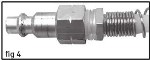
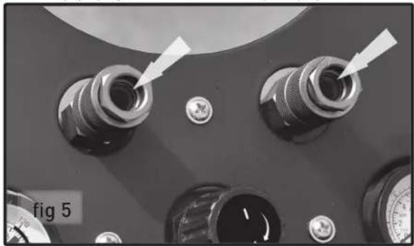
Your air compressor is supplied with two 1/4" push-connect air couplers (fi g 5). With a factory installed air coupler, your compressor is ready to accept air hoses equipped with 1/4" male air connectors (fi g 4).
NOTICE Use only air hoses rated for use with 120 psi air pressure or higher.
To install an air hose equipped with a 1/4" male connector (fi g 4):
natural_image
Close-up of a metallic mechanical component with threaded end and hexagonal nuts (no text or symbols visible)- Simply push the "connector" or "plug" into the fi tting (fi g 5) and it automatically engages.
natural_image
Close-up of a mechanical component with multiple connectors and adjustment knobs (no visible text or symbols)- Verify that air hose is securely connected to air coupler by pulling on the air hose.
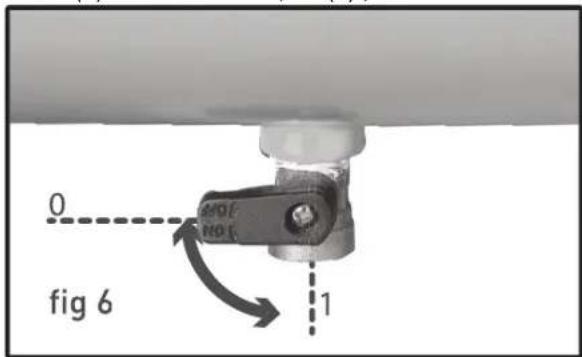
Drain Valve
- Make sure the drainage valve (fi g 6) is closed (0) and not in the open (1) position.
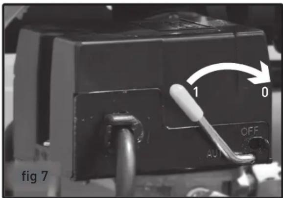
Pressure Switch
- Check that the pressure switch is moved clockwise to the OFF position (fi g 7.0).
- Ensure that the power supply you are going to use is operating normally.
- Insert the power supply cord into the power supply socket.
- Turn the pressure switch on (fi g 7.1), moving the lever to the AUTO position.
- On the reservoir pressure gauge (fi g 8.5), you can watch pressure build in the tank until the pump stops at the factory-set pressure, about 115 to 120 psi.
- This first time running your compressor and periodically thereafter, check for air leaks. If the gauge indicates pressure is going down in the tank or you hear leakage, you could apply soapy water to all joints in the air transport piping. Tighten these joints if bubbles form.
Adjusting the air pressure
Your air compressor is supplied with an air pressure regulator. This regulator (fi g 8.10) adjusts the air
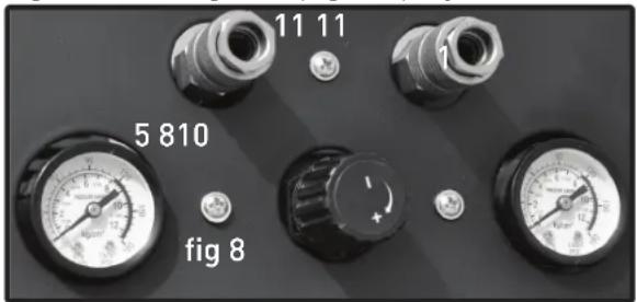
pressure supplied to the hose through the couplers (fi g 8.11).
- To increase air pressure, turn air regulator knob (fi g 8.10) clockwise.
- To decrease air pressure, turn air regulator knob counterclockwise.
- Use the outlet pressure gauge (fi g 8.8) to see the resulting pressure.
Shutting off your compressor
- Move the pressure switch to the OFF position (fi g 7.0).
- Unplug the compressor from the electrical power.
- If not draining the tank, reduce tank pressure through the air hose.
- Drain the tank by slowly opening the drain valve (fi g 6.1). Place a catch basin under the valve to protect the surface from water damage.
Cold Weather Starting
Temperatures below freezing (32 °F / 0 °C) cause the metal parts of your air compressor to contract and that makes starting more difficult. To assist the air compressor in starting in cold weather, follow these tips:
- Try to keep the air compressor stored in temperatures above 32 °F ( 0 °C ).
- Open the air tank drain valve and release all air pressure from the air tank before attempting to start in cold weather. (After air is released from air tank, close drain valve.)
- Pull the ring on the safety valve before each use to make sure the valve is functional.
- Plug the air compressor directly into a 120 volt electrical outlet. Do not use an extension cord when starting your air compressor in cold weather.
Maintenance
Daily
- Before each use,
- check for any unusual noise or vibration.
- be sure all nuts and bolts are tight.
- After each use, drain condensation from the air tank.
Monthly
- Inspect air system for leaks by applying soapy water to all joints. Tighten these joints if leaks are discovered.
Storage
When storing your compressor:
- Be sure the unit is turned OFF.
- Unplug it from power source.
- Rotate the regulator to set the outlet pressure to zero.
- Release air pressure from all hoses and air tank(s).
- Drain all moisture from air tank(s).
- Fully close drain valve(s).
- Protect electrical cord and air hoses from damage (such as being stepped on or driven over). Wrap all cords and hoses loosely around the (cooled) air compressor.
- Place air compressor in a cool, dry, safe, and indoor location.
Troubleshooting
Always inspect the compressor before use, and make sure it is in good working condition. Make sure all air vents are clear. Check the power cable to make sure it is intact and free from cracks, bare wires etc. Avoid using solvents when cleaning plastic parts, most plastics are susceptible to damage from the various types of commercial solvents.
| Trouble Possible Cause Corrective Action | ||
| Compressor will not start 1. Blown fuse or circuit breaker tripped | 1. Replace or reset fuse/circuit breaker | |
| 2. Loose electrical connections 2. Check wiring connections | ||
| Low pressure 1. Restricted air filter 1. Replace air filter | ||
| 2. Defective check valve 2. Replace check valve | ||
| 3. Air leak in safety valve 3. Check valve by pulling on ring. If condition persists, replace valve | ||
| Safety valve releases Defective pressure switch Replace pressure switch | ||
| Pressure in tank falls 1. Air leaks at joints 1. Allow the compressor to build pressure in the tank, to the max pressure if possible. Spray or brush soapy water on all air connections and look for bubbles. Tighten leaky connections. Do not over-tighten.2. If the problem continues, contact customer support for further advice. | ||
| Unloader valve leaks when pump is not running | Unloader valve seal defective Allow air in the air tank out until all pressure is released. Remove the unloader valve plug and clean the valve seal. If damaged, replace seal and re-install. | |
| Compressor stopped and will not re-start | 1. Thermal overload protector has engaged due to motor overheating | 1. Check that the main supplied voltage corresponds to the compressor specifications. An inadequate extension cord (too thin or too long) can cause the motor to overheat due to voltage drop. Excessive use (over 1 hour continuous) can cause motor overheating. Allow the motor to cool down. |
| 2. Motor windings burn-out | Contact customer support | |
| Motor does not start and makes a humming sound | Capacitor burn-out | Contact customer support |
| Motor does not start or starts slowly | Low voltage electrical supply to motor | Check that the main supplied voltage corresponds to the compressor specifications.An inadequate extension cord (too thin or too long) can cause the motor to overheat due to voltage drop.Check power quality at outlet |
| Compressor runs noisily and metallic sounds are heard Compressor will not come to max pressure | Head gasket or reed valve damaged. | Stop the compressor and contact customer support |
| Compressor doesn't provide as much air as when new and/or cuts off after a much shorter time period. | 1. Tank has reduced capacity due to water retention2. Pressure switch is out of adjustment | 1. Open drain valve to release water2. Contact customer support |
| Pump unit does not stop when the tank reaches maximum working pressure. | Defective or pressure switch out of adjustment | Stop the compressor immediately (risk of explosion) and contact customer support |
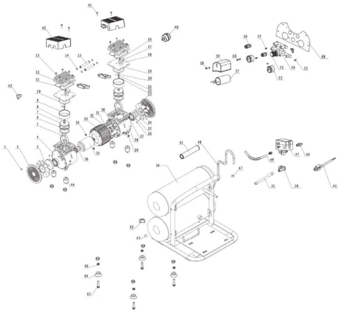
Parts List
| No. | Description |
| 1 Fan screw | |
| 2 Fan cover | |
| 3 Left fan | |
| 4 Left crankcase | |
| 5 Connecting rod | |
| 6 Piston ring | |
| 7 Pressure plate | |
| 8 Pressure plate screw | |
| 9 Cylinder | |
| 10 Cylinder O-Ring | |
| 11 Cylinder head O-Ring | |
| 12 Cylinder head | |
| 13 Cylinder head screw | |
| 14 Connecting hose O-Ring | |
| 15 Connecting hose | |
| 16 Pan head screw | |
| 17 Limit block | |
| 18 Exhaust valve plate | |
| 19 Valve plate | |
| 20 Air inflow valve plate | |
| 21 Metal strengthen sheet | |
| 22 Screw | |
| 23 Right fan | |
| 24 Crank | |
| 25 Bearing | |
| 26 Holding screw | |
| 27 Cheese head screw | |
| 28 Right crankcase | |
| 29 Leading-out line guard circle | |
| 30 Motor screw | |
| 31 Screw | |
| 32 Gasket | |
| 33 Stator | |
| 34 Bolt | |
| No. | Description |
| 35 | Rotor |
| 36 | Bearing |
| 37 | Capacitor |
| 38 | N/A |
| 39 | Air tank |
| 40 | Air filter |
| 41 | Heat cover screw |
| 42 | Plastic head cover |
| 43 | Elbow |
| 44 | Shock strut |
| 45 | Power cord with plug |
| 46 | Safety valve |
| 47 | Pressure switch |
| 48 | Unloading pipe |
| 49 | Air flow pipe |
| 50 | Check valve |
| 51 | Exhaust pipe |
| 52 | Regulator |
| 53 | Gauge |
| 54 | Manifold |
| 55 | Bolt |
| 56 | 1/4” Quick connect |
| 57 | Screw |
| 58 | Bolt |
| 59 | Capacitor cover |
| 60 | Washer |
| 61 | Hand grip |
| 62 | Drain valve |
| 63 | Cap |
| 64 | Cushion foot |
| 65 | Bolt |
| 66 | Washer |
| 67 | Unloading pipe nut |
| 68 | Panel |
Schematic Drawing
Warranty Statement
HULK makes every effort to ensure that this product meets high quality and durability standards. HULK warrants to the original retail consumer a 2-year limited warranty as of the date the product was purchased at retail and that each product is free from defects in materials. Warranty does not apply to defects due directly or indirectly to misuse, abuse, negligence or accidents, repairs or alterations and lack of maintenance. HULK shall not be liable for death, injuries to persons or property or for incidental, special or consequential damages arising from the use of our products. To take advantage of this warranty, the manufacturer part must be returned for examination by the retailer. Shipping and handling charges may apply. If a defect is found, HULK will either repair or replace the product.
Mode d'emploi
natural_image
Exterior view of a HULK POWER air compressor unit (no visible text or symbols on the device body)natural_image
Close-up of a mechanical device with hoses and a labeled component (no readable text or symbols)