
HL800 - Food Processor Hobart - Free user manual and instructions
Find the device manual for free HL800 Hobart in PDF.

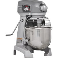
| Product type | Professional food processor (mixer-beater) |
| Brand | Hobart |
| Model | HL800 |
| Bowl capacity | 80 pints (approx. 38 liters) |
| Motor power | 3.0 HP |
| Speeds | STIR (stir) + 4 mixing speeds (1 to 4) |
| Timer | Digital SmartTimer™ with count-up and countdown, Shift-on-the-Fly™ function |
| Bowl lift | Motorized, switch controlled |
| Guard | Removable, with safety system (switch) |
| Power supply | Single-phase or three-phase, depending on configuration |
| Dimensions (approx.) | Not specified in the manual |
| Weight (approx.) | Not specified in the manual |
| Bowl material | Stainless steel |
| Compatible agitators | Flat beater B, wing whip C, standard wire whip D, dough hook ED, heavy-duty whip I, pastry knife P |
| Optional accessories | Ingredient chute, splash cover, bowl truck, bowl scraper |
| Usage | Professional (catering, bakery, pastry) |
| Maintenance | Lubrication of slides, planetary seal, agitator shaft and transmission twice a year; daily cleaning with damp cloth |
| Cleaning | Bowl and agitators washed with hot water and soapy solution; do not use hose or pressure washer |
| Safety | Locked guard, locked bowl, safety switches, emergency stop (STOP button) |
| Warranty | Contact Hobart customer service for terms |
| Repairability | Spare parts available from Hobart; service by authorized technician recommended |
| General information | Keep the user manual nearby; follow safety instructions |
Frequently Asked Questions - HL800 Hobart
User questions about HL800 Hobart
0 question about this device. Answer the ones you know or ask your own.
Ask a new question about this device
Download the instructions for your Food Processor in PDF format for free! Find your manual HL800 - Hobart and take your electronic device back in hand. On this page are published all the documents necessary for the use of your device. HL800 by Hobart.
USER MANUAL HL800 Hobart
natural_image
Exterior view of a modern K-DAV mixing robot with control panel and mesh chamber (no visible text or symbols)
FOOD EQUIPMENT GROUP
701 S. RIDGE AVENUE
TROY, OHIO 45373
937 332-3000
www.hobartcorp.com
TABLE OF CONTENTS
GENERAL....3
Safety Guidelines....4
Operation Guidelines 4
Dust Hazard 5
Warning Symbol....5
Warranty Disclaimer....5
General Information 5
INSTALLATION....6
Unpacking 6
Location 6
Electrical Connections 7
OPERATION 8
Initial Checks....8
Mixer Components 9
Controls....12
Bowl Placement....13
Agitator....14
Power Bowl Lift 14
Prepare For Mixing 15
Timer Operation (SmartTimer™)....15
Operating Notes......16
Unloading....17
Wire Cage (Fig. 13)....17
CLEANING 19
MAINTENANCE....20
Interlock Safety System 20
Lubrication 20
Transmission Belt....21
Adjustments ......21
TROUBLESHOOTING 23
Troubleshooting Guide....23
Service 23
AGITATORS AND ATTACHMENTS....24
Available Agitators and Attachments....24
INSTALLATION, OPERATION AND CARE OF LEGACY+® MIXERS
60-QUART through 140-QUART
SAVE THESE INSTRUCTIONS
GENERAL
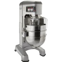
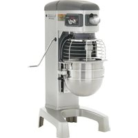
This Operation Manual is for the Hobart Legacy+® 60-Qt through 140-Qt Floor Mixers which are available in three different bowl sizes. Visit the website www.hobartcorp.com to see additional mixer sizes available from Hobart.
| Device | Bowl Size (Qt) | Motor Horsepower | Hub | Mixing Speeds |
| HL600 | 60-Qt | 2.7 HP Motor | #12 | STIR, plus four mixing speeds |
| HL600C 60 | -Qt 2.7 HP Motor #12 | Correctional Mixer, STIR, plus four mixing speeds | ||
| HL662 60 | -Qt 2.7 HP Motor #12 | Pizza Mixer, two mixing speeds | ||
| HL800 | 80-Qt | 3.0 HP Motor | N/A | STIR, plus four mixing speeds |
| HL800C 80 | -Qt 3.0 HP Motor N/A | Correctional Mixer, STIR, plus four mixing speeds | ||
| HL1400 | 140-Qt | 5.0 HP Motor | N/A | STIR, plus four mixing speeds |
| HL1400C | 140-Qt | 5.0 HP Motor | N/A | Correctional Mixer, STIR, plus four mixing speeds |
All sizes of Hobart Maximum Heavy Duty Floor Mixers feature a digital SmartTimer™ with Shift-on-the-Fly™ Controls and a power bowl lift as standard equipment.
A variety of agitators and accessories are available. These are described in a separate Use and Applications Handbook available on our website at www.hobartcorp.com.
Step down bowl sizes and agitators are available for the 60-Qt through 140-Qt mixers (e.g. 40-Qt bowl for 60-Qt mixer). Please see the website or contact you authorized Hobart Distributor for more information.
SAFETY GUIDELINES
- All operators must be properly trained in the safe operation of the mixer and attachments.
- To avoid risk of serious injury follow all precautions and instructions in this manual when installing, operating, and servicing the mixer.
- To avoid risk of serious injury, keep hands, feet, clothing, and utensils away from the bowl, bowl support, slideways, and agitator when the mixer is in operation or any of the components are moving.
- Do not operate the mixer if it is not in proper operating condition.
- Disconnect power to the mixer and follow lockout-tagout procedures before moving or servicing the mixer.
- Do not operate the mixer if parts are disassembled.
- Do not override safety switches on the mixer.
- When moving the mixer make sure it is stable to avoid tipping and keep hands and feet clear of the bottom of the mixer to avoid pinching.
- Use the STOP button to stop the mixer. Never open the wire cage or use the power bowl lift to stop the mixer.
- Do not wear loose clothing around the mixer.
- Do not inhale dust particles from mixing ingredients. Exposure to dust (including flour) may be harmful to health. When mixing ingredients that develop dust use the STIR speed until the dust is eliminated and follow the instructions in the DUST HAZARD section below.
- Do not install or leave an agitator on the mixer without a bowl in place.
- Do not use excessive force when operating, which could affect the stability of the mixer.
- Use the correct sized bowl only with agitators for that sized bowl. Double check the sizes when using a reduced sized bowl, by consulting the mixer accessories chart available at www.hobartcorp.com.
- Ensure the bowl, agitator, and wire cage are correctly fitted to the mixer.
- Stop the mixer before adding more ingredients unless using a food chute.
- Have your mixer regularly serviced; at least twice a year for typical usage. Mixers may require more or less service depending on frequency of use.
- Use the mixer in a well-lit area.
- Ensure this manual is kept in an easily accessible place near the mixer for future reference.
- Do not clean the mixer with scouring powder or a scouring pad.
- Do not clean aluminum agitators in dishwashers.
- Do not hose or pressure clean the mixer. It is important to adhere to the cleaning instructions detailed in the CLEANING section of the manual.
DUST HAZARD
In order to minimize any dust hazard, follow the instructions detailed below.
When mixing ingredients care must be taken to avoid the inhalation of dust particles e.g. flour. Reference should be made to the product supplier's data sheets to ensure adequate precautions and protections are taken.
Ingredients such as flour must be added carefully to minimize air-borne dust particles.
Carefully slit the bag while holding it in the lower part of the bowl. When mixing dry ingredients use the lowest speed and a splash cover to minimize dust emission. Mix the ingredients in the bowl using the lowest speed until the risk of producing any dust is eliminated. Fit suitable dust extraction equipment.
WARNING SYMBOL
To identify the safety messages in this manual, the following symbol has been used.
WARNING The WARNING symbol is located in the manual before information corresponding to the safe use of the mixer.
WARRANTY DISCLAIMER
Installations and repairs carried out by non-authorized service technicians may affect the mixer warranty. Using other than original replacement parts may affect the mixer warranty. Technical alterations to the mixer may affect the mixer warranty.
For warranty information, please contact Hobart Customer Care.
GENERAL INFORMATION
Hobart reserves the right to alter the design of its products without prior notice. If you have questions regarding mixer details not included in this manual, contact your local Hobart Service Office.
INSTALLATION
UNPACKING
The mixer was inspected before leaving the factory. The carrier assumes full responsibility for the safe delivery of the mixer upon acceptance of the mixer for shipping. The customer must check for possible shipping damage immediately upon receipt before moving, installing, or modifying the mixer.
If damage is found, keep all original packaging materials for inspection purposes. The customer must complete the following steps to report the damage.
- Carrier's local terminal must be notified within 5 business days of shipment receipt (note time, date, and who was spoken to), and follow up and confirm with written or electronic communication.
- Notify Hobart customer care at (800) 333-7447 within 5 business days of shipment receipt.
LOCATION
Prior to installation, test the electrical service to ensure that it matches the specifications on the mixer data plate.
Place the mixer in its operating location. There should be adequate space around the mixer for the user to operate the controls and to install and remove bowls. The area above and to the right side of the mixer should allow the top and side covers to be removed for routine maintenance and servicing.
Select a suitable flat and level surface that can support the weight of the mixer and contents of a full bowl.
Once in position, the mixer must be leveled:
- Remove the two top cover screws and the top cover.
- Place a level on the top rim of the large pulley (Fig. 1). Slide shims under the base contact surface of the mixer as required to level it front-to-back and side-to-side.
- Do not replace the top cover until installation is completed.
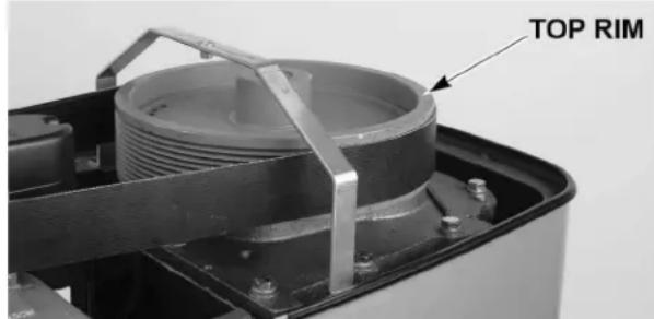
Fig. 1
80-Qt and 140-Qt mixers may be bolted to the floor using studs. Floor anchoring hardware is included with some models.
- Place the mixer in its operating location.
- Mark the floor using the four holes in the base as a template.
- Move the mixer for access to the floor.
- Using a 5/8" diameter bit, drill four holes in floor to a depth of 2".
- Drive floor anchors flush with the surface of the concrete.
-
Expand the anchor with the setting tool provided. Anchor is properly expanded when shoulder of setting tool is flush with the top of the anchor.
-
Place the mixer in its operating location over the drilled holes.
-
Install studs through the base and into the floor anchors.
-
Install flat washers, lock washers, and nuts onto the studs and tighten.
-
Saw off all threads flush with the top of the nut and remove any sharp edges.
ELECTRICAL CONNECTIONS
⚠ WARNING Electrical and grounding connections must comply with the applicable portion of the National Electrical Code and/or other local electrical codes.
⚠ WARNING Disconnect the electrical power to the mixer and follow lockout / tagout procedures.
A hole for 3/4"-trade-size conduit is located at the top of the pedestal. Make electrical connections per the wiring diagram located on the inside of the top cover.
Single-Phase Mixer:
- Connect field supply lead wires to L1 and L2.
- Connect ground wire to ground lug on the mixer.
- Cut off stripped portion of L3 on Legacy+ ® Mixer and wrap securely with electrical tape to insulate the exposed conductor.
Three-Phase Mixer:
- Connect field supply lead wires to L1, L2, and L3.
- Connect ground wire to ground lug on the mixer.
OPERATION
INITIAL CHECKS
⚠ WARNING To avoid risk of serious injury, keep hands, feet, clothing, and utensils away from the bowl, bowl support, slideways, and agitator when the mixer is in operation or when any of the components are moving.
WARNING This food mixer is only for professional use by properly trained persons.
⚠ WARNING Ensure operators have read and understood this manual and have received proper training.
⚠ WARNING Do not use the mixer without the interlocked wire cage in place.
The Legacy+® mixer is equipped with SmartTimer™ controls and a power bowl lift. Other operating parts (Fig. 3, Fig. 4, and Fig. 5) and their functions are described throughout the Operation section.
The wire cage must be in position or the mixer will not operate.
The bowl must stay in the locked position on the bowl support or the mixer will not operate.
If the bowl support is not all the way up (mix position), the mixer will not operate unless the START button is pressed and held.
If the bowl support is not in the mix position and the START button is pressed and held, the mixer will operate only in STIR speed.
Check Lubrication Before Use
This mixer is shipped with oil in the transmission. Check oil level before starting mixer (Fig. 2). Refer to the Lubrication section for applicable lubrication procedures.
Wiring Check
- Turn the SPEED dial pointer to STIR.
-
Apply power to the mixer. With the bowl locked into place, the bowl support all the way up and wire cage closed, momentarily run the machine by pushing the START and then STOP buttons.
-
Verify that the bowl lift raises and lowers per the switch direction arrows. If not, proceed to step 3a below.
a. Refer to the Electrical Connections section and follow all warnings and instructions to correct the lead wires.
Transmission Fill Plug / Oil Dipstick
natural_image
Mechanical assembly diagram showing internal components like pulley and gears (no text or labels visible)Fig. 2
MIXER COMPONENTS
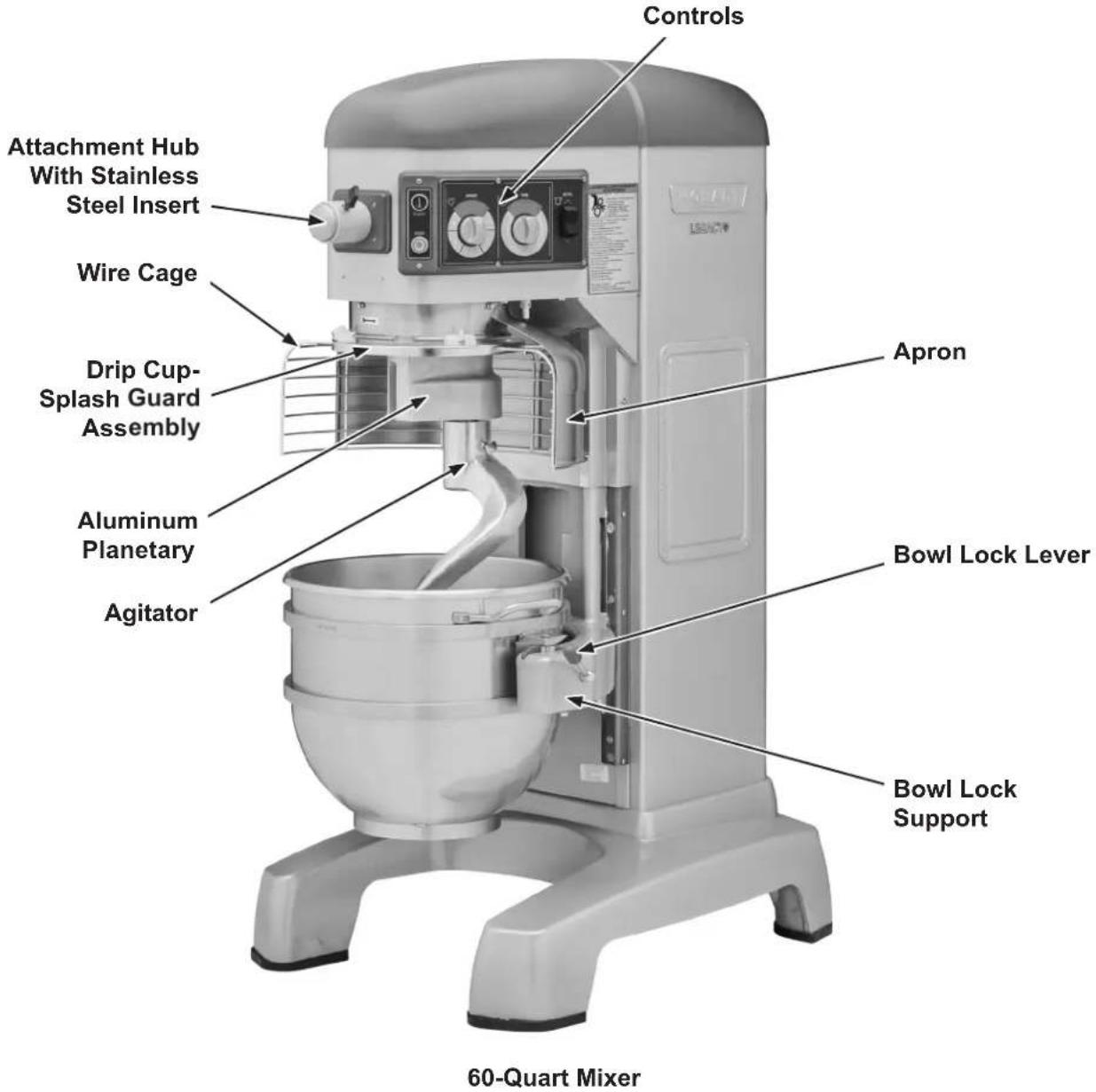
Fig. 3
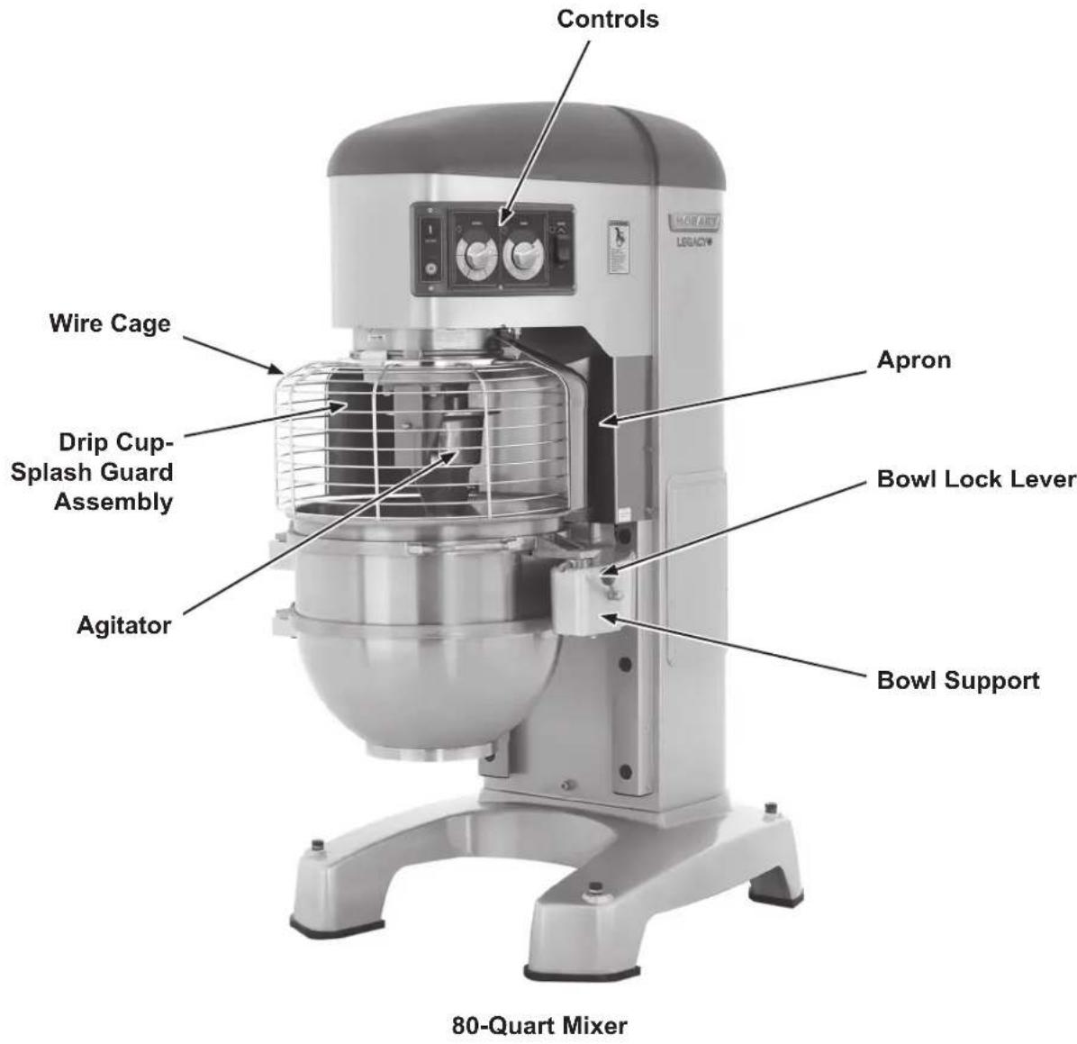
Fig. 4

Fig. 5
CONTROLS
Models HL600 and HL600C
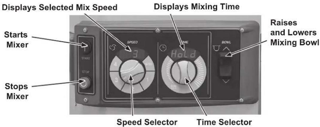
Fig. 6
| HL600 and HL600C Mixer Speeds | |
| STIR (Slow) For incorporating ingredients | |
| SPEED 1 (Low) For heavy mixtures such as pizza dough, heavy batters, and potatoes | |
| SPEED 2 (Medium-Low) For mixing cake batters, mashing potatoes, and developing bread dough | |
| SPEED 3 (Medium-High) For incorporating air into batches, as well as finishing whipped items | |
| SPEED 4 (High) For maximum, accelerated air incorporation into light batches |
Model HL662
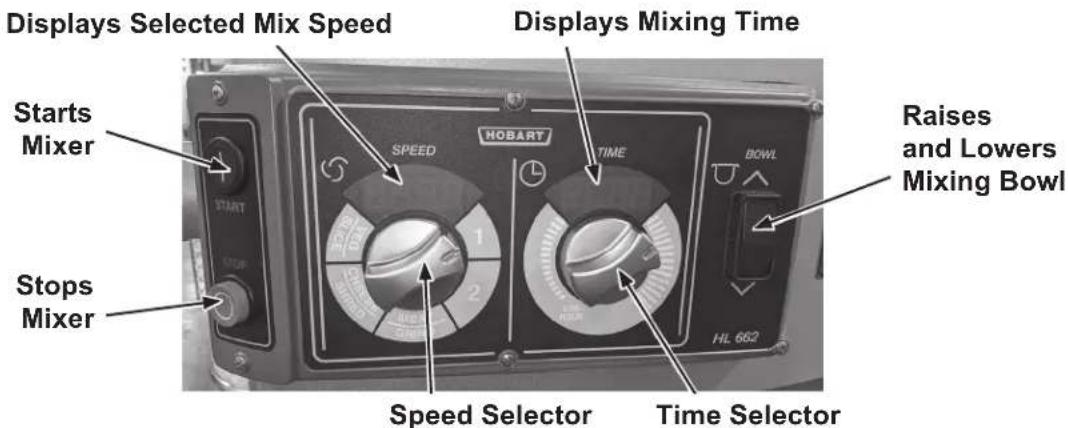
Fig. 7
| HL662 Mixer Speeds | |
| SPEED 1 (Slow) For heavy mixtures such as pizza dough, heavy batters, and potatoes | |
| SPEED 2 (Low) For developing pizza dough | |
| MEAT GRIND For grinding meat | |
| CHEESE SHRED For shredding cheese | |
| VEGETABLE SLICE For slicing vegetables |
Models HL800, HL800C, HL1400, and HL1400C
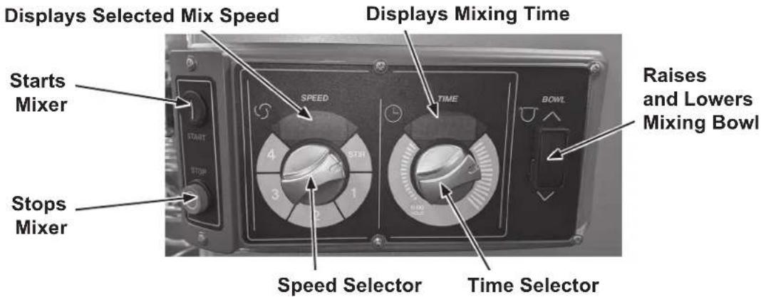
Fig. 8
| HL800, HL800C, HL1400, and HL1400C Mixer Speeds | |
| STIR (Slow) For incorporating ingredients | |
| SPEED 1 (Low) For heavy mixtures such as pizza dough, heavy batters, and potatoes | |
| SPEED 2 (Medium-Low) For mixing cake batters, mashing potatoes, and developing bread dough | |
| SPEED 3 (Medium-High) For incorporating air into batches, as well as finishing whipped items | |
| SPEED 4 (High) For maximum, accelerated air incorporation into light batches |
BOWL PLACEMENT
NOTICE The bowl must be installed onto the bowl support before the agitator is installed. The bowl is heavy and must be correctly handled and lifted to avoid personal injury.
To Install
- Fully lower the bowl support by pressing and holding the down arrow on the bowl switch (Fig. 6, Fig. 7, and Fig. 8).
- Position the bowl so the alignment pins on the left side of the bowl support (Fig. 9) fit in the holes in the bowl.
- Swing the bowl into the locked position on bowl support (Fig. 9).
To Remove
NOTICE Before lowering the bowl onto a bowl truck, always unlock the bowl and swing the bowl out slightly.
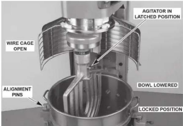
Fig. 9
- Lower the bowl by pressing and holding the down arrow on the bowl switch (Fig. 6, Fig. 7, and Fig. 8).
- Unlock bowl and swing out slightly from the locked position.
- Open the wire cage and remove the agitator.
AGITATOR
To install an agitator, the bowl must be on the bowl support and fully lowered.
To Install
- Open the wire cage. Refer to the Wire Cage section as needed.
- Place the agitator inside the bowl and align the horizontal slot on the agitator with the agitator shaft pins.
- Hold the agitator and pull the plunger pin of the agitator out (Fig. 10).
- Slide the agitator up the agitator shaft until it stops and latches.
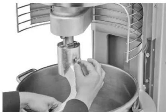
natural_image
Close-up of hands operating a kitchen mixer with a bowl of water (no visible text or symbols)Fig. 10
To Remove
- Open the wire cage. Refer to the Wire Cage section as needed.
- Lower the bowl by pressing and holding the down arrow on the bowl switch (Fig. 6, Fig. 7, and Fig. 8)
- Hold the agitator and pull the plunger of the agitator out (Fig. 10). Slide the agitator down off the agitator shaft.
POWER BOWL LIFT
NOTICE Before lowering the bowl onto a bowl truck, always unlock bowl and swing bowl out slightly (Fig. 11).
To raise the bowl, the bowl must be in the locked position. Push and hold the up arrow on the bowl switch.
To lower the bowl, push and hold the down arrow on the bowl switch.
To Raise the Bowl While Mixing
To raise the bowl while the agitator is mixing the product (when required by recipe or when using the bowl scraper attachment):
- Close the wire cage, then select a mixing speed on the SPEED dial.
- Select a count-down time or HOLD for continuous count-up mixing. Refer to the Timer Operation section as needed.
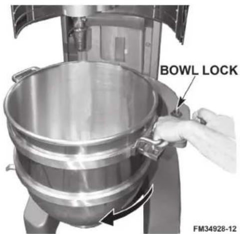
Fig. 11
-
While pressing and holding the up arrow on the bowl switch, press and hold the START button. The mixer runs only in stir speed while the bowl is rising.
-
When the bowl reaches the mix position, release the START button. The mixer automatically changes to the selected mixing speed.
NOTICE Mixing speed and time can be adjusted any time during the mixing operation without stopping the mixer.
PREPARE FOR MIXING
- Open the wire cage. Refer to the Wire Cage section as needed.
- Place the mixing bowl on the bowl support.
- Pour ingredients into the bowl.
- Swing the bowl to the locked position.
- Place the agitator inside the bowl, then attach it to the agitator shaft (Fig. 12).
- Return the wire cage to the front-center position (Fig. 13).
- Push and hold the up arrow on the bowl switch until the bowl reaches the mix position and stops.
- The mixer is now ready for mixing. Refer to the Timer Operation section.
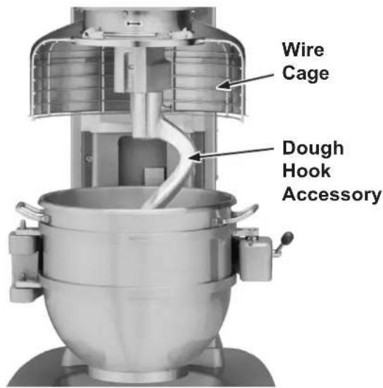
Fig. 12
TIMER OPERATION (SmartTimer™)
Using the Count-Up Mode (Continuous Mixing)
- Turn the SPEED dial to select a mix speed (the SPEED setting can be changed at any time during mixing).
NOTICE Only use STIR for incorporating ingredients. Do not use to develop dough products.
- Set the timer on hold by turning the TIME selector counterclockwise until "Hold" appears in the TIME window.
- Press the START button to begin mixing. The timer starts to count up from 00:00.
NOTICE If the wire cage is opened at any time, mixing stops. To resume mixing, close the wire cage and press the START button.
- Press the STOP button to stop the mixer; the mixing time is displayed in the TIME window.
- Press the START button to resume mixing if needed.
NOTICE When the timer reaches 20:00 minutes, it rolls over to 00:01 and continues counting until the STOP button is pressed.
Using the Count-Down Mode (Timed Mixing)
- Turn the SPEED dial to select a mix speed.
a. If the count-up mode was used for the previous batch, the desired time needs to be entered.
b. If the count-down mode was used for the previous batch, the previous time is displayed. If a different time is needed, turn the TIME selector to the desired time.
- Press the START button to begin mixing; the timer starts counting down from the set time.
a. To stop the mixer at any time, press the STOP button. To resume mixing, press the START button. For example: The mixer is started at SPEED 1 for 30 seconds and is stopped after 10 seconds. Pressing the START button will resume mixing.
b. If the mixer is stopped and a new time setting is entered, pressing the START button saves the new time setting on the current speed selection. For example: The mixer is started at SPEED 1 for 30 seconds and is stopped after 10 seconds. A new time is entered by turning the TIME selector. The new time replaces the initial 30 seconds for SPEED 1 after the START button is pressed.
c. If the time is changed while mixing, the mixer operates until the new time expires. The adjustment to the time is not stored.
d. If the speed is changed while mixing, the time reverts to the previously set time for the selected speed and counts down.
⚠ WARNING The agitator does not stop immediately. To avoid risk of serious injury, keep hands, clothing, and utensils out of the mixing bowl and away from the agitator as the agitator winds down.
NOTICE If the wire cage is opened at any time, the mixing stops. To resume the mixing, close the wire cage and press the START button.
- When the timer reaches 00:00, the mixer stops; a beeper sounds for 3 seconds. The count-down timer displays the last-entered time.
OPERATING NOTES
- Only use STIR for incorporating ingredients. Do not use it to develop dough products.
- If the mixer is stopped during mixing, the timer also stops. The timer starts again (with the time remaining) when the START button is pressed.
- The SPEED window displays the current SPEED selection.
- Turn the TIME selector clockwise to take the mixer out of the hold mode.
UNLOADING
- After the mixer has stopped, and the agitator comes to rest, unlock the bowl and swing-out slightly. Press and hold the down arrow on the bowl switch to lower the bowl.
- Open the wire cage assembly.
- Remove the agitator from the agitator shaft.
- Remove the bowl from the bowl support.
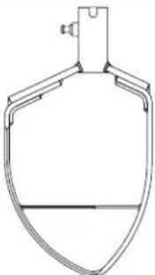
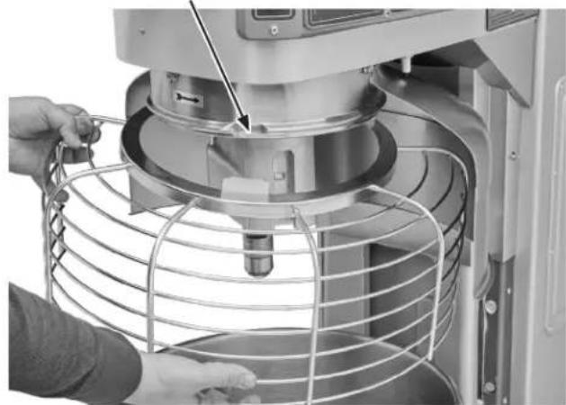
WIRE CAGE (Fig. 13)
The wire cage can be rotated out of the way to add ingredients or to access the bowl and agitator.
Note how the grooves on the retainer shoes allow the wire cage to ride around the circular ridge of the planetary drip cup.
• To open the wire cage: rotate it to your left.
• To close the wire cage: rotate it to your right until it stops in the front-center, closed position.
NOTICE The wire cage must be returned to the closed position for the mixer to operate.
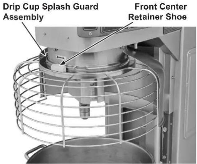
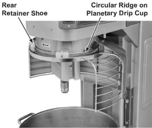
Fig. 13
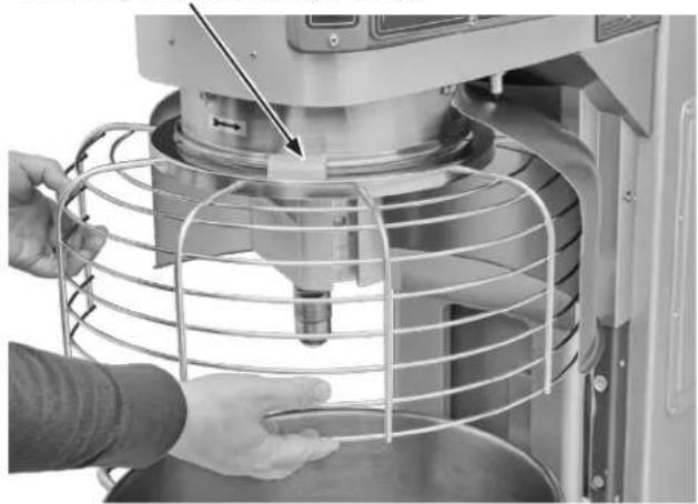
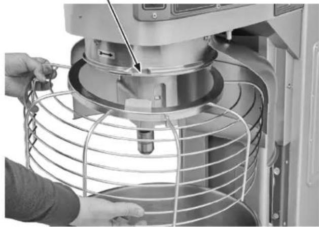
Remove and Clean Wire Cage (Fig. 14)
-
Lower the bowl. Remove the agitator and bowl.
-
While holding the wire cage securely with both hands, rotate it to your left until the front-center retainer shoe reaches the gap in the circular ridge of the planetary drip cup.
-
Lower the front of the wire cage and move the wire cage slightly to the rear so the rear retainer shoes clear the ridge of the drip cup. The wire cage can now be removed.
Front Center Retainer Shoe
natural_image
Close-up of hands operating a kitchen mixer with a mesh cage and tool, no visible text or symbolsGap in Circular Ridge
natural_image
Close-up of a kitchen mixer with a hand adjusting the rim, showing internal components and no visible text or symbols.Fig. 14
-
Wash the wire cage in a sink, rinse with clear water, and dry with a clean cloth.
-
The stainless steel splash guard can be wiped off and/or washed with a cloth or sponge using warm, soapy water. Rinse with clear water and dry with a clean cloth.
Reinstall Wire Cage
-
Position the ring of the wire cage so the front-center retainer shoe is positioned below the gap in the circular ridge of the planetary drip cup.
-
Position the grooves so the rear retainer shoes straddle the circular ridge on the planetary drip cup.
-
Lift the front of the wire cage so the front-center retainer shoe passes up through the gap in the circular ridge on the planetary drip cup.
-
Rotate the wire cage to your right until all three retainer shoes straddle the ridge on the drip cup.
CLEANING
⚠ WARNING Disconnect the electrical power to the mixer and follow lockout / tagout procedures.
New mixer bowls and accessories (beaters, whips, and dough arms) should be thoroughly washed with hot water and a mild soap solution, rinsed with either a mild soda or vinegar solution and thoroughly rinsed with clear water before being used. This cleaning procedure should also be followed for bowls and agitators before whipping egg whites or whole eggs.
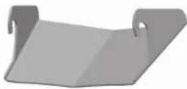
The mixer should be thoroughly cleaned daily. DO NOT use a hose to clean the mixer; it should be washed with a clean, damp cloth. The base allows ample room for cleaning under the mixer. The apron (Fig. 3, Fig. 4, and Fig. 5) may be removed for cleaning by loosening the thumb screws. DO NOT wipe down slideways (Fig. 15) when cleaning.
The drip cup-splash guard assembly (Fig. 3, Fig. 4, and Fig. 5) should be removed periodically and wiped clean.
For cleaning the wire cage refer to the Wire Cage section.
MAINTENANCE
⚠ WARNING Disconnect the electrical power to the mixer and follow lockout / tagout procedures.
⚠ WARNING Do not remove any covers or loosen any fittings while the mixer is operating. Ensure the electrical supply has been isolated before attempting to service or move the mixer.
WARNING The electronic drive control is fitted with high voltage capacitors. Isolate the mixer from the mains and allow the capacitors to discharge for 5 minutes before removing any covers.
⚠ WARNING Only Hobart trained service personnel or other properly trained and qualified personnel should carry out service.
INTERLOCK SAFETY SYSTEM
Regular inspection of the mixer's safety system is necessary to check the operation of the wire cage and bowl support interlock switches. Inspections must be performed no less than once a year.
A spare parts manual is available from Hobart Resource Center. For continued safe and reliable operation of this mixer, it is recommended that servicing is only carried out by Hobart trained service personnel.
LUBRICATION
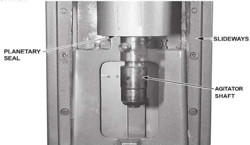
Fig. 15
Slideways
The slideways (Fig. 15) should be lubricated approximately twice a year. To reach these areas, fully lower the bowl support and remove the apron (Fig. 3, Fig. 4, and Fig. 5), which is secured by thumb screws. Wipe a thin coat of Lubriplate 630AA on the bowl pad area of the bowl supports and on each slideway. Install the apron.
Planetary Seal
Occasionally, the planetary seal (Fig. 15) may become dry and begin to squeak. To correct this, work a little lubrication (mineral oil) under the lip of the seal.
Agitator Shaft
The agitator shaft (Fig. 15) should be lubricated twice a year with a thin coat of mineral oil.
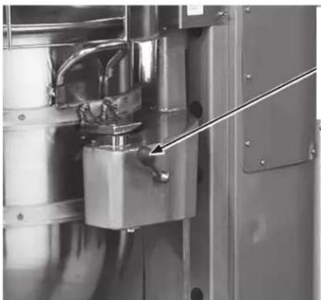
Transmission
To check the oil level, remove the top cover, which is secured by two screws. Remove the Transmission Fill Plug (Fig. 16) and check the oil level. If the oil level is below the line on the oil dipstick, add a small amount of the recommended transmission oil until it returns to the proper level. Do not overfill the transmission, as leakage may result. Contact your local Hobart Service Office for the recommended transmission oil.
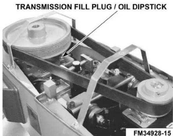
Fig. 16
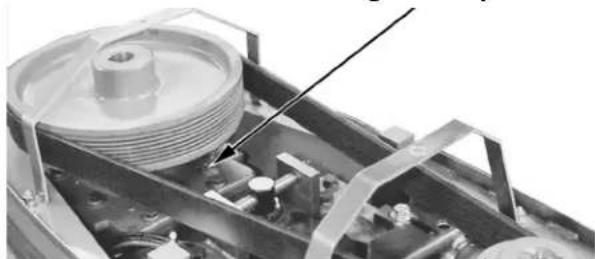
TRANSMISSION BELT
The transmission belt should be inspected yearly for wear and replace by a Hobart Service Technician if worn.
ADJUSTMENTS
Agitator Clearance
The agitator clearance should be checked periodically. The agitator must not touch the bowl, and the maximum clearance between the bottom of the bowl and an agitator is:
| Agitator Models Max Clearance | ||
| B Flat Beater HL600 | 0, HL600C, HL800, HL800C, HL1400, HL1400C 1/8" (3 mm) | |
| ED Dough Arm | HL600, HL600C, HL800, HL800C 5/16" (8 mm) | |
| HL1400, HL1400C 11/16" (17 mm) | ||
Install a bowl and agitator (e.g., beater). If the bowl and beater come into contact before the bowl support reaches its stop, adjust the stop screw. Refer to the Adjust the Bowl/Agitator Clearance section.
Measure Clearance
Pour enough flour in the bowl to cover the bottom of the bowl where the beater travels. With the bowl fully raised (beater should not touch the bottom of the bowl), briefly run the mixer at the lowest speed.
Turn off the mixer, disconnect the electrical power supply, and measure the depth of flour where the beater has traced a path. This measurement should be taken at several points around the bowl to assure accuracy.
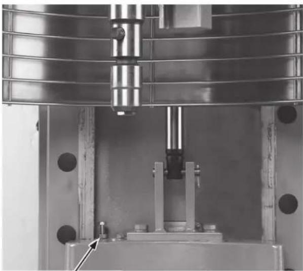
Adjust the Bowl/Agitator Clearance
- Remove the apron (Fig. 3, Fig. 4, and Fig. 5) (which is secured by thumbscrews).
- Adjust the stop screw on the left side (80-Qt and 140-Qt) and the right side (60-Qt).
- Loosen the bottom locking nut, (Fig. 17) and turn the stop screw counterclockwise to increase the clearance or clockwise to decrease the clearance.
- Tighten the locking nut while holding the stop screw.
• After the adjustments are made, replace the apron and secure it with the thumbscrews.
• Reconnect the electrical power supply.
- Carefully operate the bowl lift several times to check the adjustment.
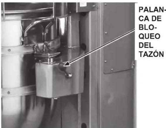
Bowl Lock Lever (Fig. 18)
• Occasionally debris may collect and cause the lever to move slowly.
- Pour very warm water around lock pin to flush out food particles that may have collected there. The water should flow through, around the pin. Be sure to have a cloth or dish under to bowl support to catch the water and food particles.
- Lubricate the pin with a thin coat of Lubriplate 630AA.
natural_image
Industrial machine with metallic components and a mechanical assembly (no visible text or symbols)STOP SCREW AND STOP NUT
Fig. 17
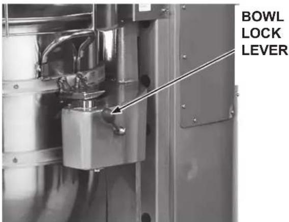
Fig. 18
TROUBLESHOOTING
TROUBLESHOOTING GUIDE
| Symptoms Possible Causes | |
| Mixer will not start. • Circuit | protector is in open position - check fuse or disconnect switch.Mixer is overloaded.Wire cage is not in the closed, front-center position.Bowl is not in closed (locked) position. |
| Agitator touches bowl. • Bowl | is not in closed (locked) position.Improper agitator clearance - refer to the Maintenance section for adjustment procedure.Agitator is not installed properly. |
| Planetary seal squeaks. • Seal | requires occasional lubrication - refer to the Maintenance section. |
| Timer displays error code (ErXX). | If the error code is flashing - disconnect electrical power from mixer for 1 minute, then reconnect. If symptoms still exist, contact your local Hobart Service office. |
SERVICE
If service is needed on this equipment, contact your local Hobart Service office @ 1-888-4HOBART.
AGITATORS AND ATTACHMENTS
Attachments for attachment hub and agitators are covered in a separate Use and Application Handbook available on our website at www.hobartcorp.com Follow the instructions accordingly.
AVAILABLE AGITATORS AND ATTACHMENTS
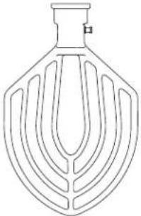 | 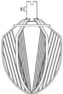 | 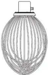 | 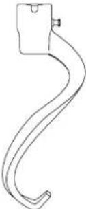 |
| “B” Flat BeaterMulti-purpose agitatortypically used for mashedpotatoes, cakes, waffles,sugar cookies, pies,shortening, icings, and more. | “C” Wing WhipHeavy whipping suchas potatoes, butter,mayonnaise, and light icing. | “D” Wire WhipMaximum blending of airinto light products suchas egg whites,meringue,whipped cream, and more. | “ED” Dough ArmMixing, folding andstretching dough such asbread, pasta, pizza, donut,and more. |
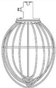 |  |  | 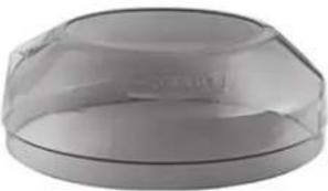 |
| “I” Wire WhipHeavy whipping such assponge cages, and lightmarshmallow. | “P” Pastry KnifeCutting action for combiningingredients such as pastryand pie dough. | Ingredient ChuteAdd ingredients to mixingbowls during operationwithout interruption. | Splash CoverControls the splash of lightingredients during mixing. |
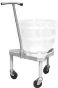 | 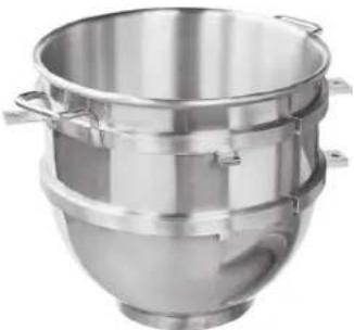 | 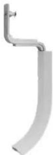 | |
| Bowl TruckMinimize strain from movinglarge, heavy mixing bowls. | Stainless BowlReliably holds ingredients. Available in stepdown sizese.g. 40-Qt bowl on 140-Qt mixer. | Bowl ScraperContinuously scrapes thesides of the bowl. | |
F48154 Rev. B (January 2025) PRINTED IN U.S.A.
HOBART
LEGACY
natural_image
Exterior view of a modern K-DAV mixing robot with control panel and mesh chamber (no visible text or symbols)
FOOD EQUIPMENT GROUP
701 S. RIDGE AVENUE
TROY, OHIO 45373
937 332-3000
www.hobartcorp.com
TABLA DE CONTENIDO
GENERAL....26
natural_image
Mechanical assembly diagram showing internal components with no visible text or symbolsFig. 2
natural_image
Close-up of hands operating a kitchen mixer with a bowl of food (no visible text or symbols)Fig. 10
natural_image
Close-up of hands cleaning a kitchen mixer with a mesh net and tool (no visible text or symbols)natural_image
Close-up of hands operating a kitchen mixer with a mesh cage (no visible text or symbols)Fig. 14
natural_image
Industrial machine with metal components and a central shaft assembly (no visible text or symbols)TORNILLO Y TUERCA DE TOPE
Fig. 17
natural_image
Exterior view of a modern multi-tiered mixing console with control panel and mesh chamber (no visible text or symbols)
FOOD EQUIPMENT GROUP
701 S. RIDGE AVENUE TROY, OHIO 45373
937 332-3000
www.hobartcorp.com
TABLE DES MATIÈRES
RENSEIGNEMENTS GÉNÉRAUX....49
natural_image
Mechanical assembly diagram showing internal components with no visible text or symbolsFig. 2
natural_image
Close-up of hands operating a kitchen mixer with a metal bowl (no visible text or symbols)Fig. 10
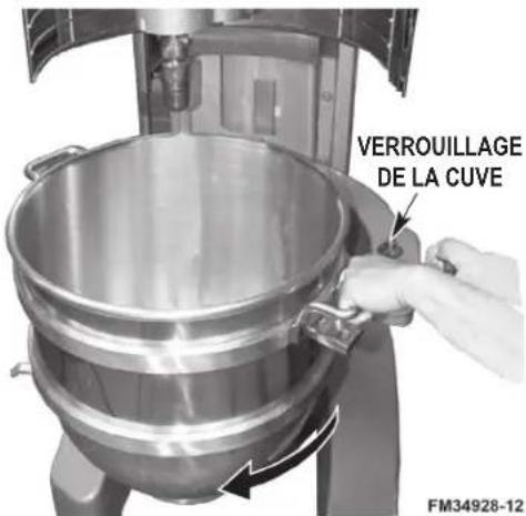
Fig. 11
PRÉPARATION POUR LE MÉLANGE
natural_image
Close-up of a kitchen mixer with mesh cage and control panel (no visible text or symbols)Patin de retenue avent centre
natural_image
Close-up of a kitchen mixer with a bowl of food inside (no visible text or symbols)Fig. 13
natural_image
Close-up of hands operating a kitchen mixer with a metal mesh cage and a small object inserted (no visible text or symbols)Circulaire La Crête
natural_image
Close-up of hands operating a kitchen mixer with a mesh cage (no visible text or symbols)Fig. 14
natural_image
Industrial machine with metallic components and a central press or actuator assembly (no visible text or symbols)VIS D'ARRÊT ET ÉCROU D'ARRÊT
Fig. 17
natural_image
Close-up of a metallic industrial machine with a lever and control panel (no visible text or symbols)LEVIER
DE VER-
ROUIL-
LAGE DE
LA CUVE
Fig. 18
DÉPANNAGE
GUIDE DE DÉPANNAGE
- TABLE OF CONTENTS
- GENERAL....3
- INSTALLATION....6
- OPERATION 8
- CLEANING 19
- MAINTENANCE....20
- TROUBLESHOOTING 23
- AGITATORS AND ATTACHMENTS....24
- INSTALLATION, OPERATION AND CARE OF LEGACY+® MIXERS
- 60-QUART through 140-QUART
- SAVE THESE INSTRUCTIONS
- GENERAL
- SAFETY GUIDELINES
- DUST HAZARD
- WARNING SYMBOL
- WARRANTY DISCLAIMER
- GENERAL INFORMATION
- INSTALLATION
- UNPACKING
- LOCATION
- ELECTRICAL CONNECTIONS
- Single-Phase Mixer:
- Three-Phase Mixer:
- OPERATION
- INITIAL CHECKS
- Check Lubrication Before Use
- Wiring Check
- CONTROLS
- Model HL662
- BOWL PLACEMENT
- To Install
- To Remove
- AGITATOR
- POWER BOWL LIFT
- To Raise the Bowl While Mixing
- PREPARE FOR MIXING
- TIMER OPERATION (SmartTimer™)
- Using the Count-Up Mode (Continuous Mixing)
- Using the Count-Down Mode (Timed Mixing)
- OPERATING NOTES
- UNLOADING
- WIRE CAGE (Fig. 13)
- Remove and Clean Wire Cage (Fig. 14)
- Reinstall Wire Cage
- CLEANING
- ⚠ WARNING Disconnect the electrical power to the mixer and follow lockout / tagout procedures.
- MAINTENANCE
- INTERLOCK SAFETY SYSTEM
- Slideways
- Planetary Seal
- Agitator Shaft
- Transmission
- TRANSMISSION BELT
- ADJUSTMENTS
- Agitator Clearance
- Measure Clearance
- Adjust the Bowl/Agitator Clearance
- Bowl Lock Lever (Fig. 18)
- TROUBLESHOOTING
- SERVICE
- AGITATORS AND ATTACHMENTS
- HOBART
- LEGACY
- TABLA DE CONTENIDO
- GENERAL....26
- TABLE DES MATIÈRES
- RENSEIGNEMENTS GÉNÉRAUX....49
- PRÉPARATION POUR LE MÉLANGE
- DÉPANNAGE
Brand : Hobart
Model : HL800
Category : Food Processor