NT65GS - Stapler HiKOKI - Free user manual and instructions
Find the device manual for free NT65GS HiKOKI in PDF.


| Product Type | Gas nailer (stapler/nailer) with lost head |
| Brand | HiKOKI (formerly Hitachi Power Tools) |
| Model | NT65GS |
| Dimensions (L × H × W) | 260 mm × 278 mm × 85 mm |
| Weight (with battery and fuel cell) | 1.8 kg (4.0 lbs) |
| Power Source | Li-Ion battery 3.6 V (model EBM315, 1.5 Ah) + fuel cell (ref. 728-981) |
| Fastener Type | 16-gauge finish nails (straight) – length from 32 mm to 65 mm |
| Magazine Capacity | 100 nails (2 strips) |
| Nailing Speed | Intermittent: 2 nails/s; continuous: 1000 nails/h |
| Trigger System | Full sequential trigger mechanism (contact + trigger) |
| Depth Adjustment | Yes, via adjustment wheel (half-turn per notch) |
| Belt Hook | Yes, reversible left/right |
| Surface Protection | Removable nose cap to protect the workpiece |
| Safety | Push lever (safety); auto-stop if magazine empty or less than 6-9 nails |
| Operating Temperature Range | 0 °C to 40 °C (32 °F to 104 °F) |
| Max Storage Temperature | 50 °C (120 °F); keep out of direct sunlight |
| Battery Charger | Model UC3SML, input 12 V DC (cigarette lighter or AC adapter), charging time ~60 min for EBM315 |
| Routine Maintenance | Clean the magazine and contact arm; lubricate with HiKOKI specific oil |
| Spare Parts and Repairability | Repairs exclusively by an authorized HiKOKI service center; use of genuine parts mandatory |
| Supplied Accessories | Safety glasses, battery, charger, cigarette lighter plug, AC adapter, Allen keys, nose cap, box |
Frequently Asked Questions - NT65GS HiKOKI
User questions about NT65GS HiKOKI
0 question about this device. Answer the ones you know or ask your own.
Ask a new question about this device
Download the instructions for your Stapler in PDF format for free! Find your manual NT65GS - HiKOKI and take your electronic device back in hand. On this page are published all the documents necessary for the use of your device. NT65GS by HiKOKI.
USER MANUAL NT65GS HiKOKI
natural_image
Technical line drawing of a mechanical device with no visible text or symbols
natural_image
Technical line drawing of a mechanical assembly (no text or symbols)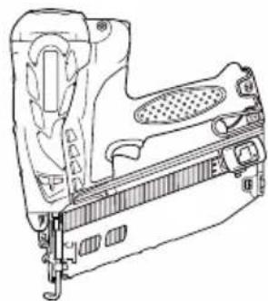
natural_image
Technical line drawing of a mechanical device with no visible text or symbols
natural_image
Technical line drawing of a mechanical device with no visible text or symbolsNT65GS NT65GA NT65GB NT50GS
DANGER
Improper use of this Nailer can result in death or serious injury! This Manual contains important information about product safety. Read and understand this Manual before operating the Nailer. Never allow anyone who has not reviewed this manual.
DANGER
ADJUSTING THE NAILING DEPTH ...... 28
USING THE HOOK 28
USING THE NOSE CAP 29
CLEARING A JAM 29
MAINTENANCE
MAINTENANCE AND INSPECTION 31
SERVICE AND REPAIRS 32
PARTS LIST 104
TABLE DE MATIERES
Français
Page
INFORMATION IMPORTANTE 35
DEFINITION DES MOTS DE SIGNALISATION .... 35
EXPLICATION DE L'ACTION DE CLOUAGE DU CLOUEUR metabo HPT .... 35
SECURITE
CONSIGNES DE SECURITE IMPORTANTES POUR L'UTILISATION DU CLOUEUR .... 36
CONSIGNES DE SÉCURITÉ IMPORTANTES À L'ÉGARD DE LA PILE À COMBUSTIBLE 41
CONSIGNES DE SÉCURITÉ IMPORTANTES POUR LE CHARGEUR DE BATTERIE..... 42
CONSIGNES DE SÉCURITÉ IMPORTANTES POUR L'UTILISATION DE LA BATTERIE ET DU CHARGEUR DE BATTERIE ..... 43
PRÉCAUTIONS À RESPECTER LORS DE L'UTILISATION DU CHARGEUR DE BATTERIE AVEC UNE SOURCE D'ALIMENTATION 12 V CC EMBARQUÉE .... 44
MISE AU REBUT D'UNE BATTERIE USÉE .. 44
RESPONSABILITES DE L'EMPLOYEUR ..... 44
UTILISATION
NOM DES PIÈCES 46
SPECIFICATIONS 48
Page
SELECTION DES CLOUS 49
ACCESSOIRES 51
ACCESSOIRES STANDARD 51
ACCESSOIRES EN OPTION 51
APPLICATIONS 51
MÉTHODE DE RECHARGE 51
natural_image
Silhouette of a person reading a book (no text or symbols)Read and understand tool labels and all of the operating instructions, safety precautions and warnings in this manual before operating or maintaining this nailer.
Failure to follow warnings could result in DEATH or SERIOUS INJURY.
Most accidents that result from the operation and maintenance of Nailers are caused by the failure to observe basic safety rules or precautions. An accident can often be avoided by recognizing a potentially hazardous situation before it occurs, and by observing appropriate safety procedures.
Basic safety precautions are outlined in the "SAFETY" section of this Manual and in the sections which contain the operation and maintenance instructions.
Hazards that must be avoided to prevent bodily injury or machine damage are identified by DANGERS and WARNINGS on the Nailer and in this Manual.
Never use this Nailer for applications other than those specified in this Manual.
DEFINITIONS OF SIGNAL WORDS
DANGER indicates an imminently hazardous situation which, if not avoided, will result in death or serious injury.
WARNING indicates a potentially hazardous situation which, if not avoided, could result in death or serious injury.
CAUTION indicates a potentially hazardous situation which, if not avoided, may result in minor or moderate injury, or may cause machine damage.
NOTE emphasizes essential information.
EXPLANATION OF THE NAILING ACTION OF THE metabo HPT NAILER
○This tool has a FULL SEQUENTIAL ACTUATION MECHANISM.
First, press the push lever against the workpiece; next, pull the trigger to drive the nail.
Follow the same sequence to continue driving nails.
SAFETY
IMPORTANT SAFETY INSTRUCTIONS FOR USING NAILERS
READ ALL INSTRUCTIONS

natural_image
Silhouette of a person reading a book (no text or symbols)This Nailer is powered by internal combustion device. This Nailer shall only be used with dispensers for combustible gas which are listed in this instruction manual.
DANGER
1. OPERATORS AND OTHERS IN WORK AREA MUST WEAR SAFETY GLASSES WITH SIDE SHIELDS.

natural_image
Simple line drawing of a person wearing sunglasses (no text or symbols)When operating the Nailer, always wear safety glasses with side shields, and make sure others in work area wear safety glasses, too. Safety glasses must conform to the requirements of American National Standards Institute, ANSI Z87.1 and provide protection against flying particles both from the front and side.
The employer must enforce the use of safety glasses by the Nailer operator and others in work area.
2. NEVER USE IN PRESENCE OF FLAMMABLE LIQUIDS OR GASES.

natural_image
Silhouette of a flame with flames, no text or symbols presentThis Nailer must not be used in a combustible environment or in presence of flammable liquids or gases, e.g. lacquer, paint, benzine, thinner or gasoline.
This Nailer produces hot exhaust gases that may ignite flammable materials and produces sparks during operation.
3. DO NOT TOUCH AROUND THE EXHAUST OUTLET.

natural_image
Simple diagram of three parallel upward arrows above a horizontal line, no text or symbols present.This Nailer produces hot exhaust gases that may flammable materials. The push lever and nose will become hot and get heated up after prolonged or rapid use.
Do not touch with bare hands.
SAFETY — Continued
DANGER
4. EXPLOSION AND FIRE HAZARD.

natural_image
Silhouette of a flame-like shape with jagged edges, resembling a stylized fire or smoke plume (no text or symbols)
The fuel cell is an aerosol dispensers with flammable contents.
Pressured container and the propellant will remain in the fuel cell.
Failure to follow instructions may result in explosion or fire.
Keep the Nailer, fuel cells and battery away from sunshine and from temperature exceeding 120^ F ( 50^ C).

Fuel cell and/or battery may burst, releasing flammable gas.
Do not pierce or burn the container, even after use.
Do not incinerate, refill, reclaim or recycle the fuel cell.
Do not spray to a naked flame or any incandescent material.
Keep away from ignition sources – No smoking.
Keep out of the reach of children.
WARNING
5. NEVER POINT TOOL AT YOURSELF OR OTHERS IN WORK AREA.

natural_image
Silhouette of a human hand with a medical instrument inserted, no text or symbols presentAlways assume the Nailer contains fasteners.
Never point the Nailer at yourself toward yourself or others, whether it contains fasteners or not. If fasteners are mistakenly
driven, it can lead to severe injuries.
Never engage in horseplay with the Nailer.
Respect the Nailer as a working implement.
6. KEEP FINGERS AWAY FROM TRIGGER WHEN NOT DRIVING FASTENERS TO AVOID ACCIDENTAL FIRING.
Never carry the Nailer with finger on trigger since you could drive a fastener unintentionally and injure yourself or someone else.
Always carry the Nailer by the handle only.
7. ALWAYS WEAR EAR AND HEAD PROTECTION.
Always wear ear protection to protect your ears from loud noise.
Always wear head protection to protect your head from flying objects.
8. USE OUTSIDE OR WELL-VENTILATED AREAS.
natural_image
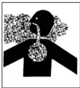
Abstract black-and-white illustration of a human head with a pipe and smoke, no text or symbols present.This Nailer exhausts carbon monoxide which are a danger to health when inhaled.
This Nailer shall not be used in enclosed or poorly ventilated areas.
Do not inhale.
9. OPERATE WITHIN PROPER TEMPERATURE RANGE.
The operating environment for this device is between 32^ F ( 0^ C) and 104^ F ( 40^ C) so ensure use within this temperature range.
The device may fail to operate below 32^ F ( 0^ C) or above 104^ F ( 40^ C).
SAFETY — Continued
WARNING
10. STORE NAILER PROPERLY WITH FUEL CELL AND BATTERY REMOVED.

When not in use, the Nailer, fuel cell and battery should be store in tool case and in a dry place.
Store indoors at temperature below 120°F (50°C).
Keep the Nailer, fuel cell and battery out of direct sunlight and out of in a vehicle. Keep out of reach of children. Look the storage area.
11. KEEP WORK AREA CLEAN.
Cluttered areas invite injuries. Clear all work areas of unnecessary tools, debris, furniture, etc.
12. KEEP VISITORS AWAY.
Do not let visitors handle the Nailer.
All visitors should be kept safely away from work area.
13. DRESS PROPERLY.
Do not wear loose clothing or jewelry as they can be caught in moving parts.
Rubber gloves and nonskid footwear are recommended when working outdoors.
Wear protective hair covering to contain long hair.
14. CHECK PUSH LEVER BEFORE USE.
The Push Lever and Chamber operate in conjunction for this device.
Remove fuel cell and battery, and then make sure the push lever operates properly. (The push lever may be called "Safety".) Never use the Nailer unless the push lever is operating properly, otherwise the Nailer could drive a fastener unexpectedly. Do not tamper with or remove the push lever, otherwise the push lever becomes inoperable.
Pull the Feeder knob with the device facing upward and press down the Push lever then confirm that the Push lever securely returns to its original position.
The Push lever operation becomes especially heavy in low temperatures and drive operations may not function.
15. KEEP ALL SCREWS AND COVERS TIGHTLY IN PLACE.
Keep all screws and covers tightly mounted. Check their condition periodically.
Never use the Nailer if parts are missing or damaged.
16. DO NOT LOAD FASTENERS WITH TRIGGER OR PUSH LEVER DEPRESSED.
When loading fasteners into the Nailer,
1) do not depress the trigger;
2) do not depress the push lever; and
3) keep the Nailer pointed downward.
17. KEEP FACE, HANDS AND FEET AWAY FROM FIRING HEAD DURING USE.
Never place your face, hands or feet closer than 8 inches (200 mm) from the firing head.
A serious injury can result if the fasteners are deflected by the workpiece, or are driven away from the point of entry.
18. PLACE NAILER PROPERLY ON WORKPIECE.
Do not drive fasteners on top of other fasteners or with the Nailer at too steep of an angle; the fasteners can ricochet and hurt someone.
19. DO NOT DRIVE FASTENERS INTO THIN BOARDS OR NEAR CORNERS AND EDGES OF WORKPIECE.
The fasteners can be driven through or away from the workpiece and hit someone.
20. NEVER DRIVE FASTENERS FROM BOTH SIDES OF A WALL AT THE SAME TIME.
The fasteners can be driven into and through the wall and hit a person on the opposite side.
SAFETY — Continued
WARNING
21. CHECK FOR LIVE WIRES.
Avoid the risk of severe electrical shock by checking for live electrical wires that may be hidden by walls, floors or ceilings. Turn off the breaker switch to ensure there are no live wires.
22. DO NOT OVERREACH.
Keep proper footing and balance at all times.
23. NEVER USE NAILER WHICH IS DEFECTIVE OR OPERATING ABNORMALLY.
If the Nailer appears to be operating unusually, making strange noises, or otherwise appears defective, stop using it immediately and arrange for repairs by a metabo HPT authorized service center.
24. TAKE FUEL CELL AND BATTERY OUT OF NAILER WHEN:
1) doing maintenance and inspection;
2) clearing a jam;
3) it is not in use;
4) leaving work area;
5) moving it to another location; and
6) handing it to another person.
Never attempt to clear a jam or repair the Nailer unless you have taken fuel cell and battery out of the Nailer and removed all remaining fasteners from the Nailer.
The Nailer should never be left unattended since people who are not familiar with the Nailer might handle it and injure the themselves.
25. STAY ALERT.
Watch what you are doing. Use common sense.
Do not operate the Nailer when you are tired.
The Nailer should never be used by you if you are under the influence of alcohol, drugs or medication that makes you drowsy.
26. HANDLE NAILER CORRECTLY.
Operate the Nailer according to this Manual.
Never allow the Nailer to be operated by children, individuals unfamiliar with its operation or unauthorized personnel.
27. NEVER USE NAILER FOR APPLICATIONS OTHER THAN THOSE SPECIFIED IN THIS MANUAL.
28. HANDLE NAILER CAREFULLY.
Do not drop the Nailer or strike the Nailer against hard surfaces; and do not scratch or engrave signs on the Nailer. Handle the Nailer carefully.
29. MAINTAIN NAILER WITH CARE.
Keep the Nailer clean and lubricated for better and safer performance.
30. USE ONLY PARTS, ACCESSORIES OR FASTENERS SUPPLIED OR RECOMMENDED BY metabo HPT.
Unauthorized parts, accessories, or fasteners may void your warranty and can lead to malfunction and resulting injuries.
Only service personnel trained by metabo HPT, distributor or employer shall repair the Nailer.
31. NEVER MODIFY OR ALTER A NAILER.
Doing so may cause it to malfunction and personal injuries may result.
SAFETY — Continued
IMPORTANT SAFETY INSTRUCTIONS FOR FUEL CELL
READ ALL INSTRUCTIONS
DANGER

natural_image
Silhouette of a flame-like object with multiple sharp edges, resembling a stylized fire or smoke plume (no text or symbols)Fuel cell, fuel and propellant are flammable under pressure. Explosion / Fire Hazard
Failure to follow all instructions may result in fire and explosion when handling dispensers for combustible gas for the purpose of storage, transportation, inserting into and taking out of the tool and disposal.

Do not smoke when handling the fuel cell.
WARNING

natural_image
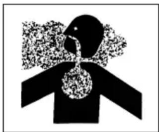
Abstract black-and-white graphic of a human head with abstract patterns, no text or symbols present.Do not inhale its contents.
In case of being inhaled ; the person affected should be taken into the open air and brought into a comfortable position.
Expanding gases cause low temperatures.
Fluid gases might cause injuries when getting in touch with skin or eyes.
In case of contact with skin ; wash the contact surface carefully with warm water and soap and apply a skin cream when dry.
In case of contact with eyes ; rinse the open eyes under running water.
Contact a doctor if necessary.
Store in well-ventilated area.
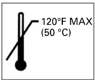
Do not store above 120^ F ( 50^ C) (e.g. direct sunlight or in a vehicle).
Do not expose to an open flame and sparks.
Do not puncture or open the fuel cell.
Do not refill, reclaim or recycle the fuel cell.
Dispose of according to local regulations for aerosol products.
Do not dispose of fuel cell with other scrap for recycling.
Keep out of reach of children.
SAFETY — Continued
IMPORTANT SAFETY INSTRUCTIONS FOR BATTERY CHARGER

WARNING
Death or serious bodily injury could result from improper or unsafe use of battery chargers.
To avoid these risks, follow these basic safety instructions:
READ ALL INSTRUCTIONS
- This manual contains important safety and operating instructions for battery charger Model UC3SML.
- Before using battery charger, read all instructions and cautionary markings on (1) battery charger, (2) battery, and (3) product using battery.
- To reduce risk of injury, charge metabo HPT rechargeable battery type EBM315. Other type of batteries may burst causing personal injury and damage.
- Do not expose battery charger to rain or snow.
- Use of an attachment not recommended or sold by the battery charger manufacturer may result in a risk of fire, electric shock, or injury to persons.
- To reduce risk of damage to electric plug and cord, pull by plug when disconnecting battery charger.
- Make sure cord is located so that it will not be stepped on, tripped over, or otherwise subjected to damage or stress.
- An extension cord should not be used unless absolutely necessary. Use of improper extension cord could result in a risk of fire and electric shock.
If extension cord must be used make sure:
a. That blades of extension cord are the same number, size, and shape as those of plug on battery charger;
b. That extension cord is properly wired and in good electrical condition; and
c. That wire size is large enough for AC ampere rating of battery charger as specified in Table 1.
Table 1 RECOMMENDED MINIMUM AWG SIZE FOR EXTENSION CORDS FOR BATTERY CHARGERS
| AC Input Rating Amperes* | AWG Size of Cord | |||
| Equal to or but less Length of Cord, Feet (Meter) greater than than 25 (7.5) 50 (15) 100 (30) 150 (45) | ||||
| 0 | 2 | 1 | 8 | 18 |
| 2 | 3 | 1 | 8 | 18 |
| 3 | 4 | 1 | 8 | 18 |
* If the input rating of a battery charger is given in watts rather than in amperes, the corresponding ampere rating is to be determined by dividing the wattage rating by the voltage rating – for example:
$$ \frac {1 , 2 5 0 \text { watts }}{1 2 5 \text { volts }} = 1 0 \text { amperes } $$
- Do not operate battery charger with damaged cord or plug-replace them immediately.
- Do not operate battery charger if it has received a sharp blow, been dropped, or otherwise damaged in any way; take it to a qualified serviceman.
- Do not disassemble battery charger; take it to a qualified serviceman when service or repair is required. Incorrect reassembly may result in a risk of electric shock or fire.
- To reduce risk of electric shock, unplug charger from receptacle before attempting any maintenance or cleaning. Removing the battery will not reduce this risk.
- This battery charger might be attached to metabo HPT battery operated tools as a standard accessory. In this case, please confirm Instruction Manual of the metabo HPT battery operated tools before using the battery charger.
SAFETY — Continued
IMPORTANT SAFETY INSTRUCTIONS FOR USE OF THE BATTERY AND BATTERY CHARGER
You must charge the battery before you use the Nailer. Before using the model UC3SML battery charger, be sure to read all instructions and cautionary statements on it, the battery and in this manual. REMEMBER: USE ONLY metabo HPT BATTERY TYPE EBM315. OTHER TYPES OF BATTERIES MAY BURST AND CAUSE INJURY! Follow these instructions to avoid the risk of injury:
WARNING
●Improper use of the battery or battery charger can lead to serious injury. To avoid these injuries:
- NEVER disassemble the battery.
- NEVER incinerate the battery, even if it is damaged or is completely worn out. The battery can explode in a fire.
- NEVER short-circuit the battery.
- NEVER insert any objects into the battery charger's air vents. Electric shock or damage to the battery charger may result.
- NEVER charge outdoors. Keep the battery away from direct sunlight and use only where there is low humidity and good ventilation.
- NEVER charge when the temperature is below 50^ F ( 10^ C) or above 104^ F ( 40^ C).
- NEVER connect two battery chargers together.
- NEVER insert foreign objects into the hole for the battery or the battery charger.
-
NEVER use a booster transformer when charging.
-
NEVER use an engine generator or DC power to charge.
- NEVER store the battery or battery charger in places where the temperature may reach or exceed 104^ F ( 40^ C).
- ALWAYS operate charger on standard household electrical power (120 volts). Using the charger on any other voltage may overheat and damage the charger.
- ALWAYS wait at least 15 minutes between charges to avoid overheating the charger.
- ALWAYS disconnect the power cord from its receptacle when the charger is not in use.
PRECAUTIONS WHEN USING THE BATTERY CHARGER WITH A DC 12V IN-CAR POWER SOURCE
- Use the battery charger correctly. Do not use the battery charger other than with a DC 12V in-car power source. The battery charger is solely for use on minus-grounded vehicles. Make sure that the minus pole of the car battery is connected to the car body.
- Keep your attention focused on driving the car.
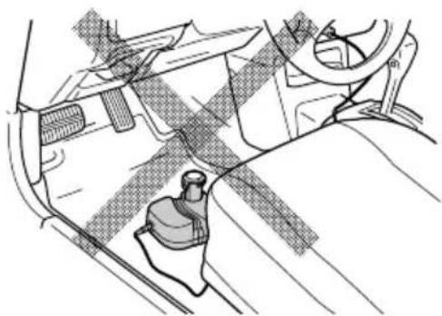
If you use the battery charger while driving, fasten the battery charger in place so that it does not move inadvertently and distract your attention from driving. Do not place the battery charger or battery under the driver's seat, irrespective of whether it is charging or not, as it may get under the brake pedal or the cable may get wrapped around the driver's feet and cause an accident. - Do not manipulate the battery charger or battery while driving as this may cause an accident.
SAFETY — Continued
- Do not leave the battery charger or battery within reach of children as this may result in an accident.
- Be use to use the cable provided.
Using a different cable could result in a fire or accident due to overheating. - Do not place the battery charger on a blanket-type car seat cover or car mat during charging as this may result in a fire or accident due to overheating.
- Do no expose the battery charger to direct sunlight during charging as this may result in a fire.
- Do not leave the vehicle unattended during charging.
DISPOSAL OF THE EXHAUSTED BATTERY

WARNING
- Do not dispose of the exhausted battery. The battery must explode if it is incinerated. The product that you have purchased contains a rechargeable battery. The battery is recyclable. At the end of it's useful life, under various state and local laws, it may be illegal to dispose of this battery into the municipal waste stream. Check with your local solid waste officials for details in your area for recycling options or proper disposal.
EMPLOYER'S RESPONSIBILITIES
- Ensure that this MANUAL is available to operators and personnel performing maintenance.
- Ensure that Nailers are used only when operators and others in work area are wearing EYE PROTECTOR.
- Enforce the use of EYE PROTECTOR by operators and others in work area.
- Keep Nailers in safe working order.
- Maintain Nailers properly.
- Ensure that Nailers which require repair are not further used before repair.
SAVE THESE INSTRUCTIONS
AND
MAKE THEM AVAILABLE TO
OTHER USERS
AND
OWNERS OF THIS TOOL!
OPERATION
NOTE:
The information contained in this Manual is designed to assist you in the safe operation of the Nailer.
Some illustrations in this Manual may show details or attachments that differ from those on your own Nailer.
NAME OF PARTS
1. Gas Finish Nailer

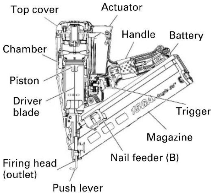

○Battery (EMB315)

2. Gas Brad Nailer
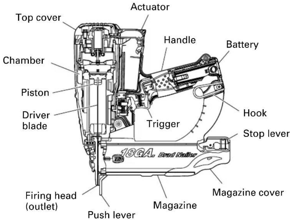
3. Battery Charger (UC3SML)

Charger connecting plug

Cigarette lighter connecting plug
Charger connecting plug

SPECIFICATIONS
1. Gas Finish Nailer
| Model NT65GS NT65GB NT65GA | |||
| DimensionsLength × Height × Width | 10-1/4" × 11" × 3-3/8"(260 mm × 278 mm × 85 mm) | 10-5/8" × 11-1/8" × 3-3/8"(268 mm × 282 mm × 85 mm) | 12" × 12" × 5"(307 mm × 305 mm × 126 mm) |
| Weight 3.7 lbs. (1.7 kg) 4.2 lbs. (1.9 kg) | |||
| Includes battery and fuel cell 4.0 lbs. (1.8 kg) 4.4 lbs. (2.0 kg) | |||
| Nail capacity 100 nails (2 strips) | 100 nails (1 strip) | ||
| Cycle rate | Intermittent: 2 nails per second 1 nail per secondContinuous: 1,000 nails per hour Continuous:900 nails per hour | ||
| Battery | EBM315 (1.5 Ah)Li-ion battery, 3.6 V | ||
| Fuel Cell | Type No. 728-981······sold separately | ||
2. Gas Brad Nailer
| Model | NT50GS |
| DimensionsLength × Height × Width | 10-5/8" × 11-1/8" × 3-3/8"(270 mm × 281 mm × 85 mm) |
| Weight | 3.7 lbs. (1.7 kg) |
| Includes battery and fuel cell | 4.0 lbs. (1.8 kg) |
| Nail capacity | 100 nails (1 strip) |
| Cycle rate | Intermittent: 2 nails per secondContinuous: 1,000 nails per hour |
| Battery | EBM315 (1.5 Ah)Li-ion battery, 3.6 V |
| Fuel Cell | Type No. 728-981······sold separately |
3. Battery Charger (UC3SML)
| Input power source | DC 12V |
| Charging time | Approx. 60 minutes EBM315 |
| Charger | Charging voltage DC 3.6 VCharging current DC 1.5 A |
| Weight | 0.4 lbs (0.2 kg) |
NOTE: The charging time may vary according to temperature and power source voltage.
NAIL SELECTION

WARNING
- Be sure to use only the genuine metabo HPT nails for the NT65GS, NT65GB, NT65GA or the NT50GS. The use of any other nails can result in tool malfunction and/or nail breakdown, leading to serious injuries.
Only nails shown in the Table below can be driven with this Nailer.
Dimensions of nails
16 Gauge finish nails (straight)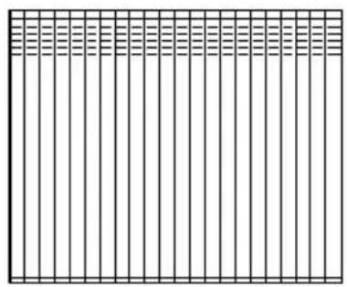 | Min. | Max. |
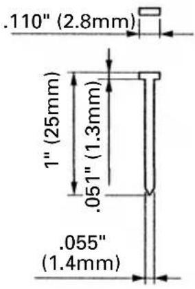 .065"(1.65mm) .065"(1.65mm) | 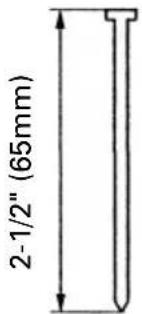 |
16 Gauge finish nails (Angle: 20°) | Min. | Max. |
 .065"(1.65mm) .065"(1.65mm) | 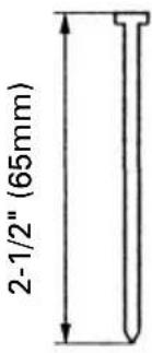 |
| 15 Gauge finish nails (Angle: 34°) | Min. | Max. |
| (3.0mm) .095" (2.4mm) .12" .045" .072" (1.8mm) | C 2-1/2" (65mm) |
| 18 Gauge brad nails (straight) | Min. | Max. |
| .075" (1.9mm) 5/8" (16mm) .043" (1.1mm) .039" (1mm) | 2" (50mm) |
ACCESSORIES

DANGER
●Accessories other than those shown below can lead to malfunction and resulting injuries.
STANDARD ACCESSORIES

①Safety glasses ....1
②Battery 1
③Charger 1
④Cigarette lighter connecting plug ..... 1
⑤AC adapter ....1
⑥Allen wrench for M4 screw 1
⑦Allen wrench for M5 screw 1
⑧Nose cap (mounted on tool) (except NT50GS) 1
⑨Nose cap (mounted on tool)
(only NT50GS) ....1
⑩Case 1
OPTIONAL ACCESSORIES
sold separately
○Fuel Cell (Code No. 728-981)
○Lubricant oil (Code No. 885-546, No. 728-986)
○Degreaser/cleaner (Code No. 728-985)
NOTE: Accessories are subject to change without any obligation on the part of metabo HPT.
APPLICATIONS
○Nailing as finishing process for areas around the doors, windows as well as edgings.
○Securing the bottom of drawers. Making various cases and cabinets.
○Cabinet and picture frame assembly, furniture trim.
○On-site and mobile home trim and molding.
CHARGING METHOD
NOTE: Before plugging into the receptacle, make sure the following points.
○The power source voltage is stated on the nameplate.
○The cord is not damaged.

WARNING
●Do not charge at voltage higher than indicated on the nameplate. If charged at voltage higher than indicated on the nameplate, the charger will burn up.
- Insert the charger connecting plug into the connecting socket of the charger.
- Connect to the power source.
When using the AC adapter
Insert the AC adapter into the receptacle.

WARNING

natural_image
Black and white illustration of a hand with a lightning bolt symbol (no text or numbers)●Do not use the electrical cord if damaged. Have it repaired immediately.
When using the cigarette lighter connecting plug
○Secure the battery charger in place in the car.
Use the strap supplied with the battery charger to fasten the battery charger in place and prevent it from moving inadvertently.

natural_image
Line drawing of a car's seatbelt with a cable and handle attachment (no text or symbols)
WARNING
- Do not place the battery charger or battery under the driver's seat. Secure the battery charger in place to prevent it from moving inadvertently as this may lead to an accident.
natural_image
Technical line drawing of a mechanical component or bracket assembly (no text or symbols)○Insert the cigarette lighter connecting plug into the cigarette lighter socket. If the plug is loose and falls out of the cigarette lighter socket, repair the socket.
As the socket may be faulty, you are recommended to contact your local car dealer. Continued use of the socket may result in an accident due to overheating.
- Insert the battery to the battery charger.

natural_image
Line drawing of a mechanical device with a cylindrical component inserted into a housing, connected to a cable (no text or symbols present)- Charging
When the battery is connected to the battery charger, charging will commence and the pilot lamp will light on.
NOTE: If the pilot lamp does not light, pull out the plug from the receptacle and check if the battery is properly mounted.
When the battery is fully charged, the pilot lamp will go out.
NOTE: The battery charging time becomes longer when a temperature is low or the voltage of the power source is too low.
When the pilot lamp does not go off even if more than four hour has passed after start of the charging, stop the charging and contact your metabo HPT AUTHORIZED SERVICE CENTER.
○Regarding the temperature of the rechargeable battery.
The temperatures for rechargeable batteries are as shown in the table below, and batteries that have become hot should be cooled for a while before being recharged.
Table 2
| Rechargeable batteries | Temperature at which the battery can be recharged |
| EBM315 | 32°F — 122°F (0°C — 50°C) |
○Regarding recharging time
Table 3 shows the recharging time required according to the type of battery.
Table 3 Recharging time (approx. min.) at 20°C
| Battery voltage (V) | Battery capacity (Ah) | |
| 1.5 Ah | ||
| 3.6 EBM | 315 60 min. | |
NOTE: The recharging time may vary according to the ambient temperature and the power supply voltage.
- Disconnect battery charger from the receptacle or cigarette lighter socket.
CAUTION
- Do not pull the plug out of the receptacle by pulling on the cord. Make sure to grasp the plug when removing from receptacle to avoid damaging cord.
- Remove the battery from the battery charger.
Supporting the battery charger with hand, pull out the battery from the battery charger.
Do not leave the battery charger or battery in the car.
Regarding electric discharge in case of new batteries, etc.
As the internal chemical substance of new batteries and batteries that have not been used for an extended period is not activated, the electric discharge might be low when using them the first and second time. This is a temporary phenomenon, and normal time required for recharging will be restored by recharging the batteries 2 – 3 times.
How to make the batteries perform longer.
○Recharge the batteries before they become completely exhausted.
When you feel that the power of the tool becomes weaker, stop using the tool and recharge its battery. If you continue to use the tool and exhaust the electric current, the battery may be damaged and its life will become shorter.
○Avoid recharging at high temperatures.
A rechargeable battery will be hot immediately after use. If such a battery is recharged immediately after use, its internal chemical substance will deteriorate, and the battery life will be shortened. Leave the battery and recharge it after it has cooled for a while.
CAUTION
- When the battery charger has been continuously used, the battery charger will be heated, thus constituting the cause of the failures. Once the charging has been completed, give 15 minutes rest until the next charging.
●If the battery is recharged when it is warm due to battery use or exposure to sunlight, the pilot lamp may not light.
The battery will not be recharged. In such a case, let the battery cool before charging. - If the battery charger does not work while the battery is mounted correctly, it is probable that the battery or charger is malfunctioning. Take it to your authorized Service Center.
BEFORE OPERATION
Read section titled "SAFETY" (pages 5 – 12).
Make sure of the followings before operation.
WORKING ENVIRONMENT
WARNING

natural_image
Silhouette of a flame with sharp edges, resembling a stylized fire or smoke plume (no text or symbols)

●No flammable gas, liquid or other flammable objects at worksite.
●Use outside or well-ventilated areas.
Do not inhale.
- Keep the Nailer, fuel cell and battery away from sunshine and from temperature exceeding 120°F (50°C).
●Keep away from ignition sources. No smoking.
●Clear the area of children or unauthorized personnel.
COLD WEATHER CARE
○Do not store the Nailer, fuel cell and battery in a cold weather environment. Keep the Nailer, fuel cell and battery in a warm area until beginning the work.
○If the Nailer, fuel cell and battery are already cold, bring it in a warm area and allow the Nailer to warm up before use. Observe temperature limit of max. 120°F (50°C).
Do not expose to an open flame and sparks!
CAUTION
●This Nailer may not drive completely below when; at low temperature fuel cell loose the required propellant force, at high temperature fuel cell overdose.
●Do not use the Nailer in the rain or where excessive moisture is present.
●This Nailer is not recommended for use at altitudes above 5,000 feet (1,500 m), or in temperature below 30°F (0°C).
PREPARING THE FUEL CELL
Read section titled "SAFTY, IMPORTANT SAFETY INSTRUCTIONS FOR FUEL CELL" (page 9).
DANGER

natural_image
Silhouette of a flame with sharp edges, resembling a stylized fire or smoke plume (no text or symbols)

natural_image
Abstract black-and-white illustration of a stylized human figure with abstract patterns (no text or symbols)●The fuel cell is flammable.
●Keep away from ignition sources.
●Do not spray to a naked flame or any incandescent material.
●Do not smoke when handling fuel cell.
- Keep stem of fuel cell away from face or skin. Expanding gases cause low temperatures. Do not contact with gases.
●Do not inhale.
●Keep out of reach of children.
CAUTION
●If the gas leaks from the metering valve or the gas cartridge after attached the metering valve, replace with the new metering valve.
●Do not attempt to reuse the metering valve.
Replace with the new metering valve.
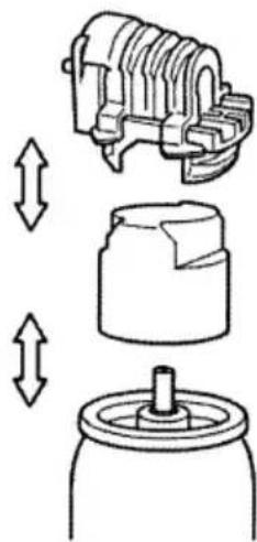
To attach the metering valve to a fuel cell:
(1) Separate the metering valve and the cap from the gas cartridge.
natural_image
Diagram showing mechanical assembly with three views: top view of a motor, side view of a gear or bushing, and bottom view of a cylindrical component (no text or symbols)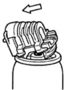
natural_image
Diagram of a mechanical device with internal components and an arrow indicating direction (no text or symbols)(2) Press forward (stem side) and downward on the front side of the metering valve.

natural_image
Hand holding a mechanical component with an arrow indicating downward motion (no text or symbols)(3) Press downward on the rear of the metering valve until it seals.
Check the metering valve:
Press the metering valve stem on fuel cell two or three times against a stationary object and release.
If gas is not dispersed, fuel cell is empty. Replace it.
Observe Safety Regulations.
The fuel cell is now ready to insert into the Nailer.
PREPARING THE BATTERY
Read section titled "SAFETY, IMPORTANT SAFETY INSTRUCTIONS FOR BATTERY CHARGER" (page 10).
You must charge the battery before use.
The charging method of battery is shown in page 18 - 20.
TESTING THE NAILER
DANGER

natural_image
Simple line drawing of a person wearing sunglasses (no text or symbols)●Operators and others in work area MUST wear safety glasses with side shields which conforms to ANSI Z87.1 specifications.
WARNING
●Never use Nailer unless push lever is operating properly.
The machine employs a preventive mechanism for unloaded operation.
The machine enters a state where the push lever cannot be pushed up. This takes place when the magazine is not loaded with nails or when the remaining number of nails becomes less than 6 or 9.
CAUTION
●Use caution not to throw the push lever tip onto wood.
Before actually beginning the nailing work, test the Nailer by using the checklist below. Conduct the tests in the following order. If abnormal operation occurs, stop using the Nailer and contact a metabo HPT authorized service center immediately.
(1) REMOVE ALL NAILS, FUEL CELL AND BATTERY FROM NAILER.
□ALL SCREWS MUST BE TIGHTENED.
☐THE PUSH LEVER AND TRIGGER MUST MOVE SMOOTHLY with pulling back the nail feeder (B). (NT50GS: Unnecessary to pulling back nail feeder)

(2) Installing the battery.
Do not operate the push lever or trigger while installing the battery.
Make sure the battery indicator light is flashing green.
If the battery indicator light is flashing red, the battery doesn't have enough power and it needs to be charged.

BATTERY INDICATOR LIGHT
Flashing GREEN: Enough power remaining (The light turns steady during operation).
Flashing RED: Insufficient power remaining (The light turns steady during operation).
OFF: The battery is extremely empty. Charge the battery.

(3) INSERT FUEL CELL INTO NAILER.
①Push up and pull out the actuator.

②Insert the fuel cell into nailer.

③Insert the stem of fuel cell into the hole of adaptor.
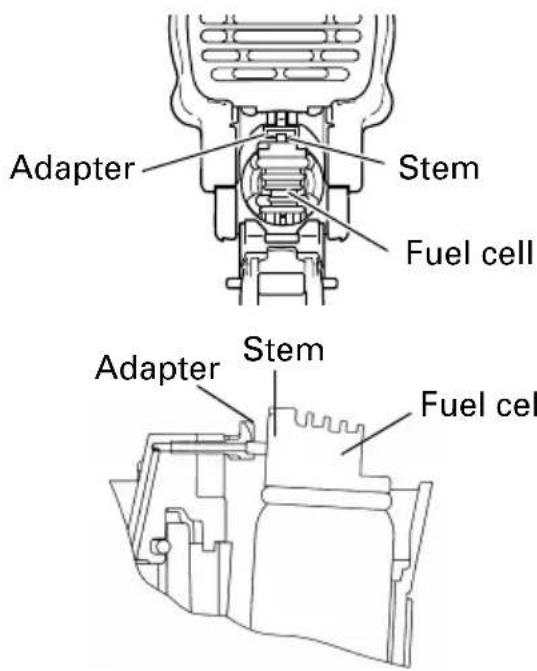
NOTE: Insert a loose adapter according to the instructions in the figure.

④Close the actuator.

(4) Remove the finger from the trigger and press the push lever against the workpiece with pulling back the nail feeder (B). (NT50GS: Unnecessary to pulling back nail feeder)
(5) Separate the push lever from the workpiece. Next, point the nailer downward, pull the trigger and then wait in that position for 5 seconds or longer.
(6) Without touching the trigger, depress the push lever against the workpiece. Pull the trigger.
(7) If no abnormal operation is observed, you may load nails in the Nailer. Drive nails into the workpiece that is the same type to be used in the actual application.
- When loading nails into Nailer, 1) do not pull trigger; 2) do not depress push lever; and 3) keep Nailer pointed downward.
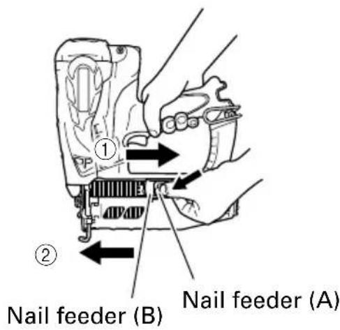
2-Action Nail Feeding!
(1) Insert nail strip into the back of the magazine.
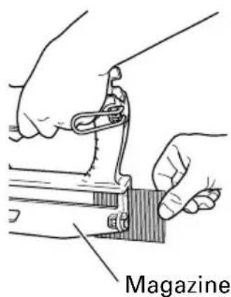
(2) Slide the nail strip forward in the magazine.

natural_image
Line drawing of hands operating a sewing machine with a tool, showing mechanical components and a directional arrow (no text or symbols)(3) Push the nail feeder (A) to engage the nail feeder (B) to the nail strip.

NOTE:
- Quietly push the nail feeder (A) and nail feeder (B) against the nail.
If the nail feeder (A) and nail feeder (B) are released from backward the magazine and bumped against the nail, the connecting adhesive of the nail can be damaged.
●Use nail strip of more than 10 nails.
●Use an unbroken nail strip with nails of all the same length.
The Nailer is now ready to operate.
Removing the nails:
①Pull the nail feeder (B) backward.
②Return the nail feeder (B) forward quietly while pushing the nail feeder (A).
③Pull out nails from the back of the magazine.

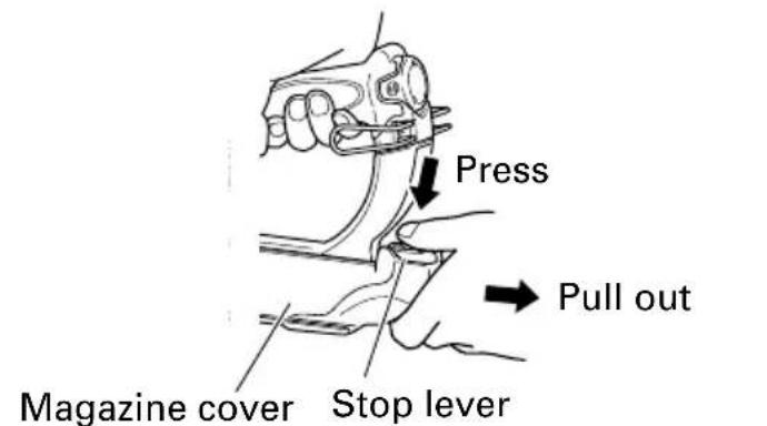
(1) Lightly press the stop lever and gently pull out the magazine cover.
(2) Set nail strip into the magazine and keep the points of nails in contact with Groove.

NOTE:
●The nails shown in page 17 can be loaded onto the side guide groove of the magazine without any adjustment. Always keep the points of nails in contact with Groove.

(3) Slide the nail strip into the blade guide.

Blade guide
(4) Confirm that nail strip is placed with side guide grooves and Groove properly, then push the magazine cover forward to be latched.
NAILER OPERATION
Read section titled "SAFETY" (pages 5 – 12).

DANGER

natural_image
Simple line drawing of a person wearing sunglasses (no text or symbols)●Operators and others in work area MUST wear safety glasses with side shields which conforms to ANSI Z87.1 specifications.

natural_image
Silhouette of a flame with multiple sharp peaks against a white background (no text or symbols)
natural_image
Simple diagram of three parallel upward arrows above a horizontal line, resembling heat or steam (no text or symbols)

●Never use in presence of fl am m a b le liquids or gases.
●Do not touch around the exhaust outlet with bare hands. The push lever and nose will become hot and get heated up after prolonged or rapid use.
● Explosion and fire hazard. Keep away from sunshine and from temperature exceeding 120°F (50°C).
●Keep away from ignition source.
●No smoking.

WARNING

natural_image
Silhouette of a hand with a pen inserted, no text or symbols present
natural_image
Silhouette of a human head with a circular object inside, surrounded by abstract patterns (no text or symbols)●NEVER point tool at yourself or others in work area.
●Keep fingers AWAY from trigger when not driving nails to avoid accidental firing.
●Use outside or well-ventilated area.
●Do not inhale its contents.
natural_image
Black-and-white illustration of a hand with a lightning bolt symbol indicating electrical hazard (no text or labels)●Do not use the electrical cord if damaged.
Have it repaired immediately.
●Never place your face, hands or feet closer than 8 inches (200 mm) from firing head when using.
- Do not drive nails on the top of other nails or with Nailer at too steep of an angle; nails can ricochet and hurt someone.
●Do not drive nails into thin boards or near corners and edges of workpiece. Nails can be driven through or away from workpiece and hit someone.
●Never drive nails from both sides of a wall at the same time. Nails can be driven into and through the wall and hit a person on the opposite side.
●Never use Nailer which is defective or operating abnormally.
●Do not use Nailer as hammer.
●Disconnect battery and fuel cell from Nailer when:
1) it is not in use;
2) leaving work area;
3) moving it to another location; and
4) handing it to another person.
●Be careful of unwanted fastener.
If pulling the trigger more when not driving nail at the temperature below 30^ F ( 0^ C), an wanted fastener will be driven.
This Nailer is equipped with a FULL SEQUENTIAL ACTUATION MECHANISM.
Explanation of FULL SEQUENTIAL ACTUATION MECHANISM nailing operation;
First, press the push lever against the workpiece;
next, pull the trigger to drive a nail.
NT65GS, NT65GA, NT65GB employ a preventive mechanism for unloaded operation.
NT65GS, NT65GA, NT65GB enter a state where the push lever cannot be pushed up. This takes place when the magazine is not loaded with nails or when the remaining number of nails becomes less than 6 or 9.
CAUTION
●Use caution not to throw the push lever tip onto wood when the push lever cannot be pushed up.
METHODS OF OPERATION
CAUTION
●Squeeze the push lever when drive a nail, otherwise the piston can not return correctly.
●Make sure the nailing depth when the temperature is above 104^ F ( 40^ C) or below 32^ F ( 0^ C).
● Using the tool for an extended period may lead to oil around the exhaust outlet or nose, resulting in spattering. To ensure that the material to be nailed stays clean, wipe off any oil that gets on the tool.
This Nailer is equipped with the push lever and does not operate unless the push lever is depressed (upward position).
It is intermittent operation (Trigger fire) only.
①Position the nail outlet on the workpiece with finger off the trigger.
②Depress the push lever firmly until it is completely depressed.
③Pull and squeeze the trigger to drive a nail.
④Remove finger from the trigger.
To continue nailing in a separate location, move the nailer along the wood, repeating steps ① - ④ as required.

Push lever
Trigger
ADJUSTING THE NAILING DEPTH
To assure that each nail penetrates to the same depth, be sure that the Nailer is always held firmly against the workpiece.
If nails are driven too deep or shallow into the workpiece, adjust the nailing in the following order.
①Remove the fuel cell and the battery from the Nailer.

②If nails are driven too deep, turn the adjuster to the shallow side. Adjustments are in half-turn increments.

flowchart
graph TD
    A["② Too Deep"] --> B["Turn Adjuster"]
    C["② Too Shallow"] --> D["Turn Adjuster"]
    B --> E["Flush"]
    D --> F["Flush"]
If nails are driven too shallow, turn the adjuster to the deep side.
③Stop turning the adjuster when a suitable position is reached for a nailing test.
④Connect the fuel cell and the battery to the Nailer.
ALWAYS WEAR SAFETY GLASSES.
Perform a nailing test.
⑤Remove the fuel cell and the battery from the Nailer.
⑥Choose a suitable position for adjuster.
USING THE HOOK
CAUTION
- If the tool falls, there is a risk that malfunction and/or physical damage can occur.
It is recommended that you also use fall-preventing wires, etc.
●Incomplete installation of the hook may result in bodily injury when used.
Hook can be installed on the left or right side.
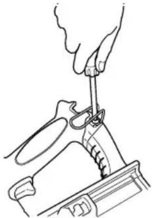
(1) Securely hold the main unit and remove the screw using a screwdriver.
natural_image
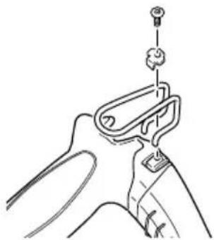
Line drawing of a hand using scissors to cut or adjust a mechanical component (no text or symbols)(2) Remove the hook and hook plate.
natural_image
Line drawing of a mechanical device with a handle and mounting bracket (no text or symbols)(3) Install the hook on the other side and securely fasten with screw.

natural_image
Line drawing of a hand using a tool to cut or inspect a mechanical component (no text or symbols)USING THE NOSE CAP

WARNING
●When attaching or detaching the nose cap, be sure to remove your finger from the trigger and remove the fuel cell and the battery from the nailer.
If you like to protect the surface of workpiece against scratches or markings made by the push lever, attach the accessory nose cap to the push lever.
①Remove the fuel cell and the battery from the nailer.
②Put the nose cap to the toe of the push lever.
③The nose cap is marked to indicate the exit point of the nail, making alignment easier.
④When not using the nose cap, secure in the storage compartment located on the reverse side of the magazine.


NOTE:
●The nose cap may reduce nailing depth due to its thickness. Re-adjustment of nailing depth is required.
CLEARING A JAM
If nails are jammed in firing head, remove it, and adjust the nailing in the following order.
CAUTION
- Remove the fuel cell and the battery from the Nailer.
①Remove the fuel cell and the battery from the Nailer.
②Remove all nails.
English
③ Release the lock lever and open guide plate.

④Remove the jammed nail with a slotted-head screwdriver.

natural_image
Line drawing of hands operating a mechanical device with tools (no text or symbols)⑤Close guide plate and latch.
NOTE:
● In case of frequent jam, contact a metabo HPT authorized service center.
MAINTENANCE
NOTE:
The information contained in this Manual is designed to assist you in the safe maintenance of the Nailer.
Some illustrations in this Manual may show details or attachments that differ from those on your own Nailer.
MAINTENANCE AND INSPECTION
Read section titled "SAFETY" (pages 5 – 12).

DANGER

natural_image
Silhouette of a flame with sharp edges, resembling a stylized fire or smoke plume (no text or symbols)●Never use and test in presence of flammable liquids or gases.
●Keep away from ignition source.
●No smoking.


WARNING
- Remove fuel cell, battery and all nails from Nailer when:
1) doing maintenance and inspection; and
2) clearing a jam.
- Inspecting the magazine
①REMOVE FUEL CELL and BATTERY.
②Clean the magazine. Remove dust and wooden chips which may have accumulated in the magazine. Lubricate it with metabo HPT Gas tool lubricant.

natural_image
Line drawing of a sewing machine with hands operating it, accompanied by a small inset component (no text or symbols)Cloth

CAUTION
- Check that the nail feeder slides smoothly by pulling it with finger. If not smooth, nails can be driven at an irregular angle and hurt someone.
- Storing

DANGER

natural_image
Silhouette of a flame with flames, no text or symbols present
●Store Nailer properly with fuel cell and battery removed.
●The fuel cell is an aerosol dispensers with flammable contents.
- When not in use, the Nailer, fuel cell and battery should be stored in tool case and in a dry place.
●Store indoors at temperature below 120°F (50°C).
○When not in use for an extended period, apply a thin coat of the lubricant to the steel parts to avoid rust.
○Do not store the Nailer, fuel cell and battery in a cold weather environment. Keep them in a warm area.
○When not in use, the Nailer, fuel cell and battery should be stored in a warm and dry place.
Keep it out of reach of children.
3. WARNING LABEL
Change the WARNING LABEL if missing or damaged.
A new WARNING LABEL is available from a metabo HPT authorized service center.

- Maintenance chart (See page 33)
- Operator troubleshooting (See pages 33–34)
- Service parts list

CAUTION
● Repair, modification and inspection of metabo HPT Power Tools must be carried out by a metabo HPT Authorized Service Center. This Parts List will be helpful if presented with the tool to the metabo HPT Authorized Service Center when requesting repair or other maintenance. In the operation and maintenance of power tools, the safety regulations and standards prescribed in each country must be observed.
MODIFICATIONS:
metabo HPT Power Tools are constantly being improved and modified to incorporate the latest technological advancements.
Accordingly, some parts may be changed without prior notice.
- Check the Screws
Loose screws are dangerous. Regularly inspect them and make sure they are tight.
CAUTION
●Using this battery charger with loosened screws is extremely dangerous.
- Check for Dust
Dust may be removed with a soft cloth or a cloth dampened with soapy water. Do not use bleach, chlorine, gasoline or thinner, for they may damage the plastics.
- Fuse replacement of cigarette lighter connecting plug
CAUTION
●For continued protection against risk of fire, replace only with same type and ratings of fuse in cigarette lighter connecting plug. 250V, 6A, DC
- Storage
Storing in a place below 104^ F ( 40^ C) and out of the reach of children.
SERVICE AND REPAIRS
WARNING
● Only service personnel trained by metabo HPT, distributor or employer shall repair the Nailer.
● Use only parts supplied or recommended by metabo HPT for repair.
All quality Nailers will eventually require servicing or replacement of parts because of wear from normal use.
NOTE:
Specifications are subject to change without any obligation on the part of metabo HPT.
Maintenance chart
| ACTION WHY HOW | ||
| Clean magazine and feeder mechanism. | Prevent a jam. Blow clean daily. | |
| Keep push lever working properly. efficient Nailer operation. | Promote operator safety and Blow clean daily. |
Operator troubleshooting
| PROBLEM CHECK | METHOD CORRECTION | |
| Nailer operates, Check for but no nail is driven. | a jam. Clear a jam. | |
| Check function of nail feeder C per page 31. | lean and lubricate. | |
| Ribbon spring weakened or Re damaged? | place ribbon spring. | |
| Check for proper nails. Use only recommended nails. | ||
| Check if the driver blade Push the driver blade with a piston is down or not. slotted-head screwdriver, and put back the piston to the highest position. | ||
| Skipping nails. Check for Intermittent feed. | proper nails. Use only recommended nails. | |
| Check function of nail feeder C per page 31. | lean and lubricate. | |
| Ribbon spring weakened or Re damaged? | place ribbon spring. | |
| Nail feeder (B) worn or Replace damaged? | nail feeder (B). | |
| Check for returning of piston. | Pull the trigger all the way. | |
| Too low temperature, warm up fuel cell under 120°F (50°C). | ||
| Check for moving of piston smoothly. | Contact metabo HPT for replacement. | |
| Replace piston ring. | ||
| Replace piston. | ||
| Replace cylinder piston ring. | ||
| Nails jam. Driven nail is bent. | Check for proper nails. Use only recommended nails. | |
| Driver blade worn? | Contact metabo HPT for replacement. | |
| Nail feeder (B) worn or Replace damaged? | nail feeder (B). | |
| The operation of the push lever not smooth. | Push lever bent? | Contact metabo HPT for replacement. |
| Check push lever's moving track, debris? | Contact metabo HPT for replacement. | |
| Fan is working, light Check indicator shows GREEN yet it doesn’t drive a nail or operation unstable. | ck for returning of piston. Push the push lever all the way. | |
| Check fuel cell, insufficient? | Exchange it with a new fuel cell. | |
| Check spark plug wire, worn out? | Contact metabo HPT for replacement. | |
| Check spark plug, grease or debris? | Contact metabo HPT for replacement. | |
| Check filter, clogged? Clean as instructed on the maintenance sheet. | ||
| Fan does not operate Magazine when push lever is magazine pressed. | gazine empty. Load more nails in the | |
| Note the color of the light indicator. | If red: charge the battery. If green: Contact metabo HPT for replacement. | |
| Unable to charge battery. | —— | Check the electrical cord. |
INFORMATION IMPORTANTE

natural_image
Silhouette of a person reading a book (no text or symbols)natural_image
Silhouette of a person reading a book (no text or symbols)natural_image
Simple line drawing of a person wearing sunglasses (no text or symbols)natural_image
Silhouette of a flame with flames, no text or symbols presentnatural_image
Simple diagram of three parallel upward arrows above a horizontal line, no text or symbols present.natural_image
Silhouette of a flame-like shape with jagged edges, no text or symbols present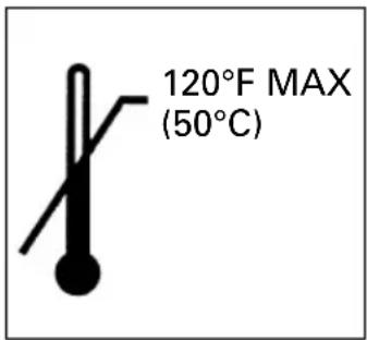
natural_image
Silhouette of a human hand with a medical instrument inserted, no text or symbols presentnatural_image
Silhouette of a human head with abstract smoke or vapor effects, no text or symbols presentnatural_image
Silhouette of a flame-like shape with no text or symbolsnatural_image
No smoking sign symbol (circle with diagonal line and smoke icon), no text presentnatural_image
Abstract black-and-white graphic of a human head with abstract patterns, no text or symbols present.other
| Dimension | Value | |-----------|-------| | Length | .075" (1.9mm) | | Width | .043" (1.1mm) | | Height | .039" (1mm) | | Width | .049" (1.25mm) | | Length | 2" (50mm) |ACCESSOIRES

DANGER
natural_image
Black and white illustration of a hand with a lightning bolt symbol (no text or numbers)natural_image
Line drawing of a car interior showing a cable inserted into a seatbelt (no text or symbols)
AVERTISSEMENT
natural_image
Technical line drawing of a mechanical assembly or bracket (no text or symbols)natural_image
Line drawing of a handheld device with a cylindrical component inserted into it, showing internal wiring and a cable (no text or symbols)- Recharge
natural_image
Silhouette of a flame with sharp edges, resembling a stylized fire or smoke plume (no text or symbols)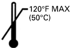

natural_image
Silhouette of a flame with multiple sharp peaks (no text or symbols)

natural_image
Silhouette of a person with a large object above their head, possibly a device or abstract form (no text or symbols visible)natural_image
Diagram showing mechanical components with bidirectional arrows indicating movement or force (no text or symbols)natural_image
Diagram of a mechanical device with internal gears and a rotating arrow (no text or symbols)natural_image
Hand holding a mechanical component with an arrow indicating downward motion (no text or symbols)natural_image
Simple line drawing of a person wearing sunglasses (no text or symbols)natural_image
Technical line drawing of a sewing machine needle and handle (no text or symbols)natural_image
Line drawing of hands operating a sewing machine with a tool, no text or symbols presentnatural_image
Simple line drawing of a person wearing sunglasses (no text or symbols)
natural_image
Silhouette of a flame with multiple sharp peaks against a white background (no text or symbols)
natural_image
Simple diagram of three parallel upward arrows above a horizontal line, resembling heat or airflow (no text or symbols)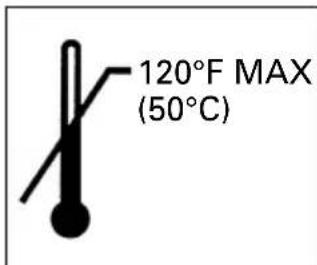

natural_image
Silhouette of a hand with a pen inserted, no text or symbols present
natural_image
Silhouette of a human head with a mouth and abstract pattern, no text or symbols present
natural_image
Black-and-white illustration of a hand with a lightning bolt symbol indicating electrical hazard (no text or labels)natural_image
Line drawing of a hand using a tool to adjust or install a mechanical component (no text or symbols present)natural_image
Technical line drawing of a mechanical clamp or bracket assembly (no text or symbols)natural_image
Line drawing of a hand using a tool to adjust or install a mechanical component (no text or symbols present)UTILISATION DU CAPUCHON DE BEC

AVERTISSEMENT

REMARQUE :
natural_image
Line drawing of hands using a tool to adjust or install a mechanical component (no text or symbols visible)natural_image
Silhouette of a flame with sharp edges, resembling a stylized fire or smoke plume (no text or symbols)
natural_image
Line drawing of a sewing machine with hands operating it, accompanied by a small component (no text or symbols)Tissu

ATTENTION
natural_image
Silhouette of a flame with flames, no text or symbols present
natural_image
Technical line drawing of a mechanical assembly with no visible text or symbolsnatural_image
Silhouette of a person reading a book (no text or symbols)natural_image
Silhouette of a person reading a book (no text or symbols)natural_image
Simple line drawing of a person wearing sunglasses (no text or symbols)natural_image
Silhouette of a flame with multiple sharp peaks against a white background (no text or symbols)natural_image
Simple diagram of three parallel upward arrows above a horizontal line (no text or symbols)natural_image
Silhouette of a flame-like shape with jagged edges, resembling a stylized fire or smoke plume (no text or symbols)
natural_image
Silhouette of a human hand with a pen inserted, no text or symbols presentnatural_image
Abstract black-and-white illustration of a human head with smoke or vapor rising (no text or symbols)natural_image
Silhouette of a flame-like shape with no text or symbolsnatural_image
Silhouette of a human head with abstract pattern overlay (no text or symbols)natural_image
Black and white illustration of a hand with a lightning bolt symbol (no text or numbers)natural_image
Line drawing of a car's seatbelt with a cable inserted into the seat (no text or symbols)
ADVERTENCIA
natural_image
Technical line drawing of a car interior showing steering wheel, dashboard, and seatbelt components (no text or labels)natural_image
Technical line drawing of a mechanical device with a cylindrical component inserted into a housing (no text or symbols)4. Carga
natural_image
Silhouette of a flame with no text or symbols

natural_image
Silhouette of a flame-like shape with jagged edges, resembling a stylized fire or smoke plume (no text or symbols)
natural_image
Abstract black-and-white illustration of a human head with a stylized object inside, no text or symbols present.natural_image
Diagram showing three mechanical components with bidirectional arrows indicating movement or force (no text or symbols present)natural_image
Diagram of a mechanical device with internal gears and a rotating arrow (no text or symbols)natural_image
Hand holding a mechanical component with an arrow indicating downward motion (no text or symbols)natural_image
Simple line drawing of a person wearing sunglasses (no text or symbols)natural_image
Technical line drawing of a sewing machine handle and boot (no text or symbols)natural_image
Line drawing of hands operating a sewing machine with a clasp, no text or symbols presentnatural_image
Simple line drawing of a person wearing sunglasses (no text or symbols)natural_image
Silhouette of a flame with no text or symbols
natural_image
Simple diagram of three parallel upward arrows above a horizontal line, no text or symbols present.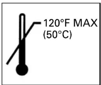


ADVERTENCIA

natural_image
Silhouette of a hand with a pen inserted, no text or symbols present
natural_image
Abstract black-and-white graphic of a human head with abstract patterns, no text or symbols present.natural_image
Black and white illustration of a hand with a lightning bolt symbol (no text or numbers)Palanca de empuje Gatillo
natural_image
Line drawing of a hand using a tool to adjust or install a mechanical component (no text or symbols present)natural_image
Line drawing of a mechanical device with a handle and mounting bracket (no text or symbols)natural_image
Line drawing of a hand using a tool to cut or install a mechanical component (no text or symbols present)NT65GS, NT65GA, NT65GB

natural_image
Line drawing of hands using a tool to adjust or install a mechanical component (no text or symbols visible)natural_image
Silhouette of a flame with sharp edges (no text or symbols)
ADVERTENCIA
natural_image
Line drawing of hands operating a sewing machine with a small inset device nearby (no text or symbols)Paño

PRECAUCIÓN
natural_image
Silhouette of a flame with no text or symbols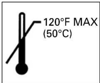
natural_image
Technical line drawing of a mechanical assembly with no visible text or symbolsNT65GS
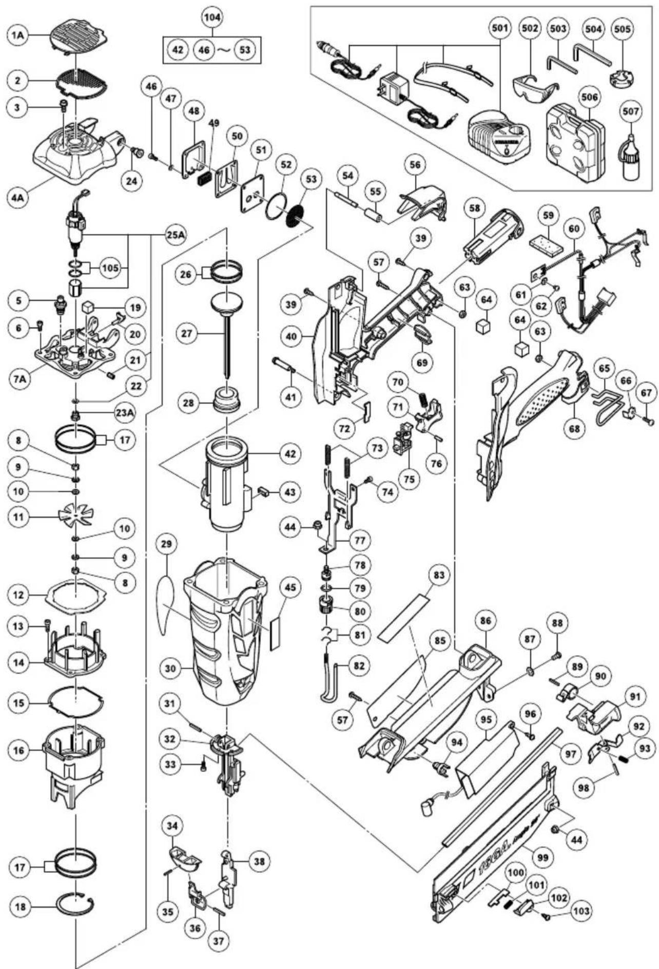
| ITEM NO. | PART NAME | Q'TY |
| 1A F | ILTER COVER 1 | |
| 2 F | ILTER MESH 1 | |
| 3 | HEX. SOCKET HD. BOLT (W/FLANGE)M5×10 | 1 |
| 4A T | TOP COVER 1 | |
| 5 | S P ARK PLUG (A) 1 | |
| 6 N | YLOCK BOLT M4×12 4 | |
| 7A O | YLINDER HEAD 1 | |
| 8 N | UT M3 2 | |
| 9 | SPRING WASHER M3 2 | |
| 10 W | ASHER M3 2 | |
| 11 F | AN | 1 |
| 12 R | UBBER PLATE | 1 |
| 13 H | EX. SOCKET HD. BOLT M4×16 | 4 |
| 14 CH | AMBER HEAD | 1 |
| 15 G | ASKET | 1 |
| 16 CH | AMBER | 1 |
| 17 P | STON RING (B) | 4 |
| 18 RETAINING RING FOR D40 HOLE | 1 | |
| 19A | MOTOR ASS'Y | 1 |
| 20 P | ACKING | 1 |
| 21 A | DAPTER | 1 |
| 22 H | EX. SOCKET SET SCREW M4×5 | 2 |
| 23 S | HAFT RUBBER WASHER | 1 |
| 24A | SHAFT COVER | 1 |
| 25 P | STON RING (A) | 2 |
| 26 P | STON | 1 |
| 27 P | STON BUMPER | 1 |
| 28 N | AME PLATE | 1 |
| 29 HOUSING | 1 | |
| 30 P | IN | 1 |
| 31 BL | ADE GUIDE | 1 |
| 32 H | EX. SOCKET HD. BOLT M4×12 | 3 |
| 33 LOCK PLATE | 1 | |
| 34 LOCK LEVER COVER | 1 | |
| 35 R | OLL PIN D3×10 | 1 |
| 36 LOCK LEVER | 1 | |
| 37 R | OLL PIN D3×16 | 1 |
| 38 LOCK SPRING | 1 | |
| 39 GUIDE PLATE | 1 | |
| 40 H | EX.SHOULDER BOLT M5 | 2 |
| 41 | SEAL LOCK HEX. SOCKET HD. BOLT M4×8 | 4 |
| 42 BELLEVILLE SPRING H8 | 4 | |
| 43 BUFFER COVER | 1 | |
| 44 M | UFFLER | 1 |
| 45 REED VALVE | 1 | |
| 46 BUFFER PLATE | 1 | |
| 47 O | -RING | 1 |
| 48 M | ESH | 1 |
| 49 T | APPING SCREW (W/FLANGE) D4×16 | 2 |
| 50 H | HANDLE (B) | 1 |
| 51 H | EX. SHOULDER BOLT M4×32 | 1 |
| 52 C | YLINDER | 1 |
| 53 CH | AMBER STOP RUBBER | 1 |
| 54 N | YLON NUT M5 | 3 |
| 55 | BRAND PLATE | 1 |
| ITEM NO. | PART NAME | Q'TY |
| 56 CELL PIN | 1 | |
| 57 P PE RUBBER 1 | ||
| 58 ACTUATER | 1 | |
| 59 TAPPING SCREW (W/FLANGE) D4×20 | 2 | |
| 60 BATTERY EBM315 | 2 | |
| 61 SUPPORT (B) | 1 | |
| 62 INTERNAL WIRE (A) | 1 | |
| 63 WASHER M4 1 | ||
| 64 MACHINE SCREW M4×10 | 1 | |
| 65 LOCK NUT M4 2 | ||
| 66 PACKING | 2 | |
| 67 HOOK | 1 | |
| 68 HOOK PLATE | 1 | |
| 69 TRUSS HD. SCREW M4 | 1 | |
| 70 HANDLE (A) | 1 | |
| 71 TERMINAL SUPPORT 1 | ||
| 72 TRIGGER STOPPER | 1 | |
| 73 TRIGGER | 1 | |
| 74 TRIGGER SPRING | 1 | |
| 75 CORD COVER PLATE | 1 | |
| 76 CHAMBER SPRING | 2 | |
| 77 HEX. SOCKET HD. BOLT M4×10 | 2 | |
| 78 PIN D3×20 | 1 | |
| 79 PUSH LEVER ARM | 1 | |
| 80 PUSH LEVER PIECE | 1 | |
| 81 O-RING | 1 | |
| 82 ADJUSTER | 1 | |
| 83 RATCHET SPRING | 2 | |
| 84 PUSH LEVER (A) | 1 | |
| 86 CAUTION LABEL (A) | 1 | |
| 87 WARNING LABEL | 1 | |
| 88 MAGAZINE COVER | 1 | |
| 89 BOLT WASHER M5 | 2 | |
| 90 MACHINE SCREW M5×15 | 2 | |
| 91 ROLL PIN D3×16 | 1 | |
| 92 RIBBON SPRING | 1 | |
| 93 NAIL FEEDER (B) 1 | ||
| 94 PRISM | 1 | |
| 95 CONTROLLER | 1 | |
| 96 TAPPING SCREW (W/FLANGE) D4×12 | 1 | |
| 97 NAIL RAIL | 1 | |
| 98 PUSHING SPRING | 1 | |
| 99 NAIL FEEDER (A) | 1 | |
| 100 ROLL PIN D2.5×26 | 1 | |
| 101 MAGAZINE | 1 | |
| 102 CYLINNDER ASS'Y (A) | 1 | |
| 103 O-RING | 2 | |
| 501 CHARGER (UC3SML) | 1 | |
| 502 SAFETY GLASSES | 1 | |
| 503 HEX. BAR WRENCH 4MM | 1 | |
| 504 HEX. BAR WRENCH 3MM | 1 | |
| 505 NOSE CAP (A) | 1 | |
| 506 CASE | 1 | |
NT65GA

NT65GA
| ITEM NO. | PART NAME | Q'TY |
| 1 FILTER COVER 1 | ||
| 2 FILTER MESH 1 | ||
| 3 | HEX. SOCKET HD. BOLT (W/FLANGE)M5×10 | 1 |
| 4 TOP COVER 1 | ||
| 5 | S P ARK PLUG (A) 1 | |
| 6 NYLOCK BOLT M4×12 4 | ||
| 7 CYLINDER HEAD 1 | ||
| 8 NUT M3 2 | ||
| 9 SPRING WASHER M3 2 | ||
| 10 WASHER M3 2 | ||
| 11 FAN 1 | ||
| 12 RUBBER PLATE | 1 | |
| 13 HEX. SOCKET HD. BOLT M4×16 | 4 | |
| 14 CHAMBER HEAD | 1 | |
| 15 GASKET | 1 | |
| 16 CHAMBER | 1 | |
| 17 PISTON RING (B) | 4 | |
| 18 RETAINING RING FOR D40 HOLE | 1 | |
| 19 PACKING | 1 | |
| 20 ADAPTER | 1 | |
| 21 HEX. SOCKET SET SCREW M4×5 | 2 | |
| 22 SHAFT RUBBER WASHER | 1 | |
| 23 SHAFT COVER | 1 | |
| 24 HEX.SHOULDER BOLT M5 | 2 | |
| 25 MOTOR ASS'Y | 1 | |
| 26 PISTON RING (A) | 2 | |
| 27 PISTON | 1 | |
| 28 PISTON BUMPER | 1 | |
| 29 NAME PLATE | 1 | |
| 30 HOUSING | 1 | |
| 31 GUIDE PIN | 1 | |
| 32 ROLL PIN D3×16 | 2 | |
| 33 BLADE GUIDE | 1 | |
| 34 | SEAL LOCK HEX. SOCKET HD. BOLTM4×12 | 3 |
| 35 LOCK LEVER COVER | 1 | |
| 36 ROLL PIN D3×10 | 1 | |
| 37 LOCK LEVER | 1 | |
| 38 GUIDE PLATE | 1 | |
| 39 TAPPING SCREW (W/FLANGE) D4×16 | 2 | |
| 40 HANDLE (B) | 1 | |
| 41 HEX. SHOULDER BOLT M4×32 | 1 | |
| 42 CYLINDER | 1 | |
| 43 CHAMBER STOP RUBBER | 1 | |
| 44 NYLON NUT M5 | 3 | |
| 45 BRAND PLATE | 1 | |
| 46 TAPPING SCREW (W/FLANGE) D4×20 | 2 | |
| 47 | SEAL LOCK HEX. SOCKET HD. BOLTM4×8 | 4 |
| 48 BELLEVILLE SPRING M4 | 4 | |
| 49 BUFFER COVER | 1 | |
| 50 MUFFLER | 1 | |
| 51 REED VALVE | 1 | |
| 52 BUFFER PLATE | 1 | |
| 53 O-RING | 1 | |
| 54 MESH | 1 | |
| 55 CELL PIN | 1 | |
| ITEM NO. | PART NAME | Q'TY |
| 56 P | PE RUBBER 1 | |
| 57 A | CTUATER | 1 |
| 58 B | ATTERY EBM315 | 2 |
| 59 S | UPPORT (B) | 1 |
| 60 IN | TERNAL WIRE (A) | 1 |
| 61 W | ASHER M4 1 | |
| 62 M | ACHINE SCREW M4×10 | 1 |
| 63 L | OCK NUT M4 2 | |
| 64 P | ACKING | 2 |
| 65 H | HANDLE (A) | 1 |
| 66 T | TERMINAL SUPPORT 1 | |
| 67 T | RIGGER SPRING | 1 |
| 68 T | RIGGER | 1 |
| 69 P | N D3×20 | 1 |
| 70 C | ORD COVER PLATE | 1 |
| 71 C | HAMBER SPRING | 2 |
| 72 T | RIGGER STOPPER | 1 |
| 73 | SEAL LOCK HEX. SOCKET HD. BOLT M4×10 | 2 |
| 74 P | JUSH LEVER ARM | 1 |
| 75 P | JUSH LEVER PIECE | 1 |
| 76 O | RING (S-8) 1 | |
| 77 A | ADJUSTER | 1 |
| 78 R | ATCHET SPRING | 2 |
| 79 P | JUSH LEVER (A) | 1 |
| 80 W | WARNING LABEL | 1 |
| 81 C | AUTION LABEL (A) | 1 |
| 82 N | UT M4 1 | |
| 83 M | AGAZINE COVER | 1 |
| 84 B | OLT WASHER M5 | 2 |
| 85 M | ACHINE SCREW M5×15 | 2 |
| 86 H | OOK | 1 |
| 87 H | OOK PLATE | 1 |
| 88 T | RUSS HD. SCREW M4 | 1 |
| 89 R | ROLL PIN D3×16 | 1 |
| 90 R | BBON SPRING | 1 |
| 91 N | AIL FEEDER (B) 1 | |
| 92 N | AIL FEEDER (A) | 1 |
| 93 P | JUSHING SPRING | 1 |
| 94 R | ROLL PIN D2.5×26 | 1 |
| 95 P | RISM | 1 |
| 96 C | ONTROLLER | 1 |
| 97 T | APPING SCREW (W/FLANGE) D4×12 | 1 |
| 98 N | AIL RAIL | 1 |
| 99 M | AGAZINE | 1 |
| 100 | PUSH STOPPER (A) | 1 |
| 101 | LOCK SPRING | 1 |
| 102 | PUSH STOPPER COVER | 1 |
| 103 | TAPPING SCREW (W/FLANGE) D3×10 | 1 |
| 104 | CYLINNDER ASS'Y | 1 |
| 105 | O-RING | 2 |
| 501 | CHARGER (UC3SML) | 1 |
| 502 | SAFETY GLASSES | 1 |
| 503 | HEX. BAR WRENCH 3MM | 1 |
| 504 | HEX. BAR WRENCH 4MM | 1 |
| 505 | NOSE CAP (A) | 1 |
| 506 | CASE | 1 |
NT65GB
| ITEM NO. | PART NAME | Q'TY |
| 1A F | ILTER COVER 1 | |
| 2 F | ILTER MESH 1 | |
| 3 | HEX. SOCKET HD. BOLT (W/FLANGE)M5×10 | 1 |
| 4A T | TOP COVER 1 | |
| 5 | S P ARK PLUG (A) 1 | |
| 6 N | YLOCK BOLT M4×12 4 | |
| 7A O | YLINDER HEAD 1 | |
| 8 N | UT M3 2 | |
| 9 | SPRING WASHER M3 2 | |
| 10 W | ASHER M3 2 | |
| 11 F | AN | 1 |
| 12 R | UBBER PLATE | 1 |
| 13 H | EX. SOCKET HD. BOLT M4×16 | 4 |
| 14 CH | AMBER HEAD | 1 |
| 15 G | ASKET | 1 |
| 16 CH | AMBER | 1 |
| 17 P | STON RING (B) | 4 |
| 18 RETAINING RING FOR D40 HOLE | 1 | |
| 19 P | ACKING | 1 |
| 20 A | DAPTER | 1 |
| 21 H | EX. SOCKET SET SCREW M4×5 | 2 |
| 22 S | SHAFT RUBBER WASHER | 1 |
| 23A | SHAFT COVER | 1 |
| 24 H | EX.SHOULDER BOLT M5 | 2 |
| 25A | MOTOR ASS'Y | 1 |
| 26 P | STON RING (A) | 2 |
| 27 P | STON | 1 |
| 28 P | STON BUMPER | 1 |
| 29 N | AME PLATE | 1 |
| 30 HOUSING | 1 | |
| 31 P | N | 1 |
| 32 BL | ADE GUIDE | 1 |
| 33 | SEAL LOCK HEX. SOCKET HD. BOLT M4×12 | 3 |
| 34 L | OCK LEVER COVER | 1 |
| 35 R | OLL PIN D3×10 | 1 |
| 36 L | OCK LEVER | 1 |
| 37 R | OLL PIN D3×16 | 1 |
| 38 G | UIDE PLATE | 1 |
| 39 T | APPING SCREW (W/FLANGE) D4×16 | 2 |
| 40 H | HANDLE (B) | 1 |
| 41 H | EX. SHOULDER BOLT M4×32 | 1 |
| 42 CYLINDER | 1 | |
| 43 CH | AMBER STOP RUBBER | 1 |
| 44 NYLON NUT M5 | 3 | |
| 45 BRAND PLATE | 1 | |
| 46 | SEAL LOCK HEX. SOCKET HD. BOLT M4×8 | 4 |
| 47 BELLEVILLE SPRING H8 | 4 | |
| 48 BUFFER COVER | 1 | |
| 49 M | UFFLER | 1 |
| 50 REED VALVE | 1 | |
| 51 BUFFER PLATE | 1 | |
| 52 O | -RING | 1 |
| 53 M | ESH | 1 |
| 54 CELL PIN | 1 | |
| 55 P | PE RUBBER 1 | |
| ITEM NO. | PART NAME | Q'TY |
| 56 A | CTUATER | 1 |
| 57 T | APPING SCREW (W/FLANGE) D4×20 | 2 |
| 58 B | ATTERY EBM315 | 2 |
| 59 S | UPPORT (B) | 1 |
| 60 I | INTERNAL WIRE (A) | 1 |
| 61 W | ASHER M4 1 | |
| 62 M | ACHINE SCREW M4×10 | 1 |
| 63 L | OCK NUT M4 2 | |
| 64 P | ACKING | 2 |
| 65 H | OOK | 1 |
| 66 H | OOK PLATE | 1 |
| 67 T | RUSS HD. SCREW M4 | 1 |
| 68 H | HANDLE (A) | 1 |
| 69 T | TERMINAL SUPPORT 1 | |
| 70 T | RIGGER SPRING | 1 |
| 71 T | RIGGER | 1 |
| 72 C | ORD COVER PLATE | 1 |
| 73 C | CHAMBER SPRING | 2 |
| 74 | SEAL LOCK HEX. SOCKET HD. BOLT M4×10 | 2 |
| 75 T | RIGGER STOPPER | 1 |
| 76 P | N D3×20 | 1 |
| 77 P | JUSH LEVER ARM | 1 |
| 78 P | JUSH LEVER PIECE | 1 |
| 79 O | RING (S-8) 1 | |
| 80 A | ADJUSTER | 1 |
| 81 R | ATCHET SPRING | 2 |
| 82 P | JUSH LEVER (A) | 1 |
| 83 C | AUTION LABEL (A) | 1 |
| 85 W | WARNING LABEL | 1 |
| 86 M | AGAZINE COVER | 1 |
| 87 B | OLT WASHER M5 | 2 |
| 88 M | ACHINE SCREW M5×15 | 2 |
| 89 R | ROLL PIN D3×16 | 1 |
| 90 R | BBON SPRING | 1 |
| 91 N | AIL FEEDER (B) 1 | |
| 92 N | AIL FEEDER (A) | 1 |
| 93 S | TOPPER SPRING (C) | 1 |
| 94 P | RISM | 1 |
| 95 C | CONTROLLER | 1 |
| 96 T | APPING SCREW (W/FLANGE) D4×12 | 1 |
| 97 N | AIL RAIL | 1 |
| 98 R | ROLL PIN D2.5×26 | 1 |
| 99 M | AGAZINE | 1 |
| 100 | PUSH STOPPER (B) | 1 |
| 101 | PUSH STOPPER SPRING | 1 |
| 102 | PUSH STOPPER COVER | 1 |
| 103 | TAPPING SCREW (W/FLANGE) D3×10 | 1 |
| 104 | CYLINNDER ASS'Y | 1 |
| 105 | O-RING | 2 |
| 501 | CHARGER (UC3SML) | 1 |
| 502 | SAFETY GLASSES | 1 |
| 503 | HEX. BAR WRENCH 3MM | 1 |
| 504 | HEX. BAR WRENCH 4MM | 1 |
| 505 | NOSE CAP (A) | 1 |
| 506 | CASE | 1 |
NT50GS

NT50GS
| ITEM NO. | PART NAME | Q'TY |
| 1 FILTER COVER 1 | ||
| 2 FILTER MESH 1 | ||
| 3 HEX. SOCKET HD. BOLT (W/FLANGE)M5×10 | 1 | |
| 4 TOP COVER 1 | ||
| 5 S P ARK PLUG (A) 1 | ||
| 6 NYLOCK HEX. SOCKET HD. BOLT M4×12 4 | ||
| 7 CYLINDER HEAD 1 | ||
| 8 NUT M3 (10 PCS.) 2 | ||
| 9 SPRING WASHER M3 2 | ||
| 10 WASHER M3 2 | ||
| 11 FAN 1 | ||
| 12 RUBBER PLATE | 1 | |
| 13 HEX. SOCKET HD. BOLT M4×16 | 4 | |
| 14 CHAMBER HEAD | 1 | |
| 15 GASKET | 1 | |
| 16 CHAMBER | 1 | |
| 17 PISTON RING (B) | 4 | |
| 18 RETAINING RING FOR D30 HOLE | 1 | |
| 19 MOTOR ASS'Y | 1 | |
| 20 O-RING (S-12) | 2 | |
| 21 PACKING | 1 | |
| 22 ADAPTER | 1 | |
| 23 HEX. SOCKET SET SCREW M4×5 | 2 | |
| 24 SHAFT RUBBER WASHER | 1 | |
| 25 SHAFT COVER | 1 | |
| 26 PISTON RING (A) | 2 | |
| 27 PISTON | 1 | |
| 28 PISTON BUMPER | 1 | |
| 29 NAME PLATE | 1 | |
| 30 HOUSING | 1 | |
| 31 PIN | 1 | |
| 32 BLADE GUIDE | 1 | |
| 33 SEAL LOCK HEX. SOCKET HD. BOLT M4×12 | 3 | |
| 34 NYLOCK HEX. SOCKET HD. BOLT M4×10 2 | ||
| 35 LOCK LEVER COVER | 1 | |
| 36 GUIDE PLATE | 1 | |
| 37 ROLL PIN D3×10 | 1 | |
| 38 LOCK LEVER | 1 | |
| 39 ROLL PIN D3×16 | 1 | |
| 40 HEX. SHOULDER BOLT M5 | 2 | |
| 41 SEAL LOCK HEX. SOCKET HD. BOLT M4×8 | 4 | |
| 42 BELLEVILLE SPRING H8 | 4 | |
| 43 BUFFER COVER | 1 | |
| 44 MUFFLER | 1 | |
| 45 REED VALVE | 1 | |
| 46 BUFFER PLATE | 1 | |
| 47 O-RING | 1 | |
| 48 MESH | 1 | |
| 49 TAPPING SCREW (W/FLANGE) D4×16 | 2 | |
| 50 HANDLE (B) | 1 | |
| 51 HEX. SHOULDER BOLT M4×32 | 1 | |
| 52 CYLINDER | 1 | |
| 53 CHAMBER STOP RUBBER | 1 | |
| 54 NYLON NUT M5 | 1 | |
| 55 BRAND PLATE | 1 | |
| ITEM NO. | PART NAME | Q'TY |
| 56 CELL PIN | 1 | |
| 57 P PE RUBBER 1 | ||
| 58 ACTUATER | 1 | |
| 59 BATTERY EBM315 | 2 | |
| 60 SUPPORT (B) | 1 | |
| 61 INTERNAL WIRE (A) | 1 | |
| 62 WASHER M4 1 | ||
| 63 MACHINE SCREW M4×10 | 1 | |
| 64 TAPPING SCREW (W/FLANGE) D4×20 | 2 | |
| 65 LOCK NUT M4 2 | ||
| 66 PACKING | 2 | |
| 67 HOOK | 1 | |
| 68 HOOK PLATE | 1 | |
| 69 TRUSS HD. SCREW M4 | 1 | |
| 70 HANDLE (A) | 1 | |
| 71 TERMINAL SUPPORT 1 | ||
| 72 TRIGGER STOPPER | 1 | |
| 73 TRIGGER | 1 | |
| 74 TRIGGER SPRING | 1 | |
| 75 PIN D3×20 | 1 | |
| 76 CORD COVER PLATE | 1 | |
| 77 CHAMBER SPRING | 2 | |
| 78 SEAL LOCK HEX. SOCKET HD. BOLT M4×10 | 2 | |
| 79 PUSH LEVER ARM | 1 | |
| 80 PUSH LEVER PIECE | 1 | |
| 81 O-RING (S-8) 1 | ||
| 82 ADJUSTER | 1 | |
| 83 RATCHET SPRING | 2 | |
| 84 PUSHING LEVER (A) | 1 | |
| 85 CAUTION LABEL 1 | ||
| 86 WARNING LABEL | 1 | |
| 87 CONTROLLER COVER | 1 | |
| 88 CONTROLLER | 1 | |
| 89 TAPPING SCREW (W/FLANGE) D4×12 | 1 | |
| 95 MAGAZINE COVER | 1 | |
| 91 ROLL PIN D3×20 | 1 | |
| 92 STOP LEVER | 1 | |
| 93 SPRING | 1 | |
| 94 PLATE | 1 | |
| 90 MAGAZINE | 1 | |
| 96 PRISM | 1 | |
| 97 NAIL FEEDER | 1 | |
| 98 NAIL PLATE 1 | ||
| 99 FEEDER PIECE | 1 | |
| 100 FEED SPRING | 1 | |
| 101 CYLINDER ASS'Y (A) | 1 | |
| 102 CYLINDER HEAD ASS'Y | 1 | |
| 501 CHARGER (UC3SML) | 1 | |
| 502 SAFETY GLASSES | 1 | |
| 503 HEX. BAR WRENCH 3MM | 1 | |
| 504 HEX. BAR WRENCH 4MM | 1 | |
| 505 NOSE CAP (A) | 1 | |
| 506 CASE | 1 | |

Please contact Koki Holdings America Ltd. at 1-800-59-TOOLS (toll free), or metabo HPT AUTHORIZED POWER TOOL SERVICE CENTER regarding COLLECTION.

Pour le RAMASSAGE, contacter Koki Holdings America Ltd. au 1-800-59-TOOLS (appel gratuit), ou UN SERVICE APRÈS-VENTE D'OUTILS ÉLECTRIQUE AGRÉÉ PAR metabo HPT.

Shinagawa Intercity Tower A, 15-1, Konan 2-chome, Minato-ku, Tokyo 108-6020, Japan
Distributed by
Koki Holdings America Ltd.
1111 Broadway Ave, Braselton, Georgia, 30517
Koki Holdings America Ltd. Canadian Branch
3405 American Drive, Units 9-10, Mississauga, ON, L4V 1T6


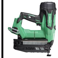
- DANGER
- MAINTENANCE
- TABLE DE MATIERES
- Français
- SECURITE
- UTILISATION
- DEFINITIONS OF SIGNAL WORDS
- EXPLANATION OF THE NAILING ACTION OF THE metabo HPT NAILER
- SAFETY
- IMPORTANT SAFETY INSTRUCTIONS FOR USING NAILERS
- READ ALL INSTRUCTIONS
- OPERATORS AND OTHERS IN WORK AREA MUST WEAR SAFETY GLASSES WITH SIDE SHIELDS.
- NEVER USE IN PRESENCE OF FLAMMABLE LIQUIDS OR GASES.
- DO NOT TOUCH AROUND THE EXHAUST OUTLET.
- SAFETY — Continued
- EXPLOSION AND FIRE HAZARD.
- WARNING
- NEVER POINT TOOL AT YOURSELF OR OTHERS IN WORK AREA.
- KEEP FINGERS AWAY FROM TRIGGER WHEN NOT DRIVING FASTENERS TO AVOID ACCIDENTAL FIRING.
- ALWAYS WEAR EAR AND HEAD PROTECTION.
- USE OUTSIDE OR WELL-VENTILATED AREAS.
- OPERATE WITHIN PROPER TEMPERATURE RANGE.
- STORE NAILER PROPERLY WITH FUEL CELL AND BATTERY REMOVED.
- KEEP WORK AREA CLEAN.
- KEEP VISITORS AWAY.
- DRESS PROPERLY.
- CHECK PUSH LEVER BEFORE USE.
- KEEP ALL SCREWS AND COVERS TIGHTLY IN PLACE.
- DO NOT LOAD FASTENERS WITH TRIGGER OR PUSH LEVER DEPRESSED.
- KEEP FACE, HANDS AND FEET AWAY FROM FIRING HEAD DURING USE.
- PLACE NAILER PROPERLY ON WORKPIECE.
- DO NOT DRIVE FASTENERS INTO THIN BOARDS OR NEAR CORNERS AND EDGES OF WORKPIECE.
- NEVER DRIVE FASTENERS FROM BOTH SIDES OF A WALL AT THE SAME TIME.
- CHECK FOR LIVE WIRES.
- DO NOT OVERREACH.
- NEVER USE NAILER WHICH IS DEFECTIVE OR OPERATING ABNORMALLY.
- TAKE FUEL CELL AND BATTERY OUT OF NAILER WHEN:
- STAY ALERT.
- HANDLE NAILER CORRECTLY.
- NEVER USE NAILER FOR APPLICATIONS OTHER THAN THOSE SPECIFIED IN THIS MANUAL.
- HANDLE NAILER CAREFULLY.
- MAINTAIN NAILER WITH CARE.
- USE ONLY PARTS, ACCESSORIES OR FASTENERS SUPPLIED OR RECOMMENDED BY metabo HPT.
- NEVER MODIFY OR ALTER A NAILER.
- IMPORTANT SAFETY INSTRUCTIONS FOR FUEL CELL
- Fuel cell, fuel and propellant are flammable under pressure. Explosion / Fire Hazard
- Do not inhale its contents.
- Expanding gases cause low temperatures.
- Store in well-ventilated area.
- Dispose of according to local regulations for aerosol products.
- IMPORTANT SAFETY INSTRUCTIONS FOR BATTERY CHARGER
- IMPORTANT SAFETY INSTRUCTIONS FOR USE OF THE BATTERY AND BATTERY CHARGER
- PRECAUTIONS WHEN USING THE BATTERY CHARGER WITH A DC 12V IN-CAR POWER SOURCE
- DISPOSAL OF THE EXHAUSTED BATTERY
- EMPLOYER'S RESPONSIBILITIES
- SAVE THESE INSTRUCTIONS
- AND
- MAKE THEM AVAILABLE TO
- OTHER USERS
- OWNERS OF THIS TOOL!
- OPERATION
- NOTE:
- NAME OF PARTS
- Gas Finish Nailer
- Gas Brad Nailer
- Battery Charger (UC3SML)
- SPECIFICATIONS
- NAIL SELECTION
- Dimensions of nails
- ACCESSORIES
- OPTIONAL ACCESSORIES
- APPLICATIONS
- CHARGING METHOD
- ○Regarding recharging time
- CAUTION
- BEFORE OPERATION
- WORKING ENVIRONMENT
- COLD WEATHER CARE
- PREPARING THE FUEL CELL
- Observe Safety Regulations.
- PREPARING THE BATTERY
- Read section titled "SAFETY, IMPORTANT SAFETY INSTRUCTIONS FOR BATTERY CHARGER" (page 10).
- TESTING THE NAILER
- The machine employs a preventive mechanism for unloaded operation.
- ●Use caution not to throw the push lever tip onto wood.
- BATTERY INDICATOR LIGHT
- INSERT FUEL CELL INTO NAILER.
- 2-Action Nail Feeding!
- NAILER OPERATION
- METHODS OF OPERATION
- ADJUSTING THE NAILING DEPTH
- USING THE HOOK
- USING THE NOSE CAP
- CLEARING A JAM
- English
- MAINTENANCE AND INSPECTION
- WARNING LABEL
- MODIFICATIONS:
- SERVICE AND REPAIRS
- INFORMATION IMPORTANTE
- ACCESSOIRES
- AVERTISSEMENT
- UTILISATION DU CAPUCHON DE BEC
- REMARQUE :
- ATTENTION
- ADVERTENCIA
- Carga
- PRECAUCIÓN
- Koki Holdings America Ltd.
- Koki Holdings America Ltd. Canadian Branch
Brand : HiKOKI
Model : NT65GS
Category : Stapler