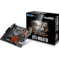
USER MANUAL B150M-ITX ASROCK
Published October 2015
Copyright©2015 ASRock INC. All rights reserved.
Copyright Notice:
No part of this documentation may be reproduced, transcribed, transmitted, or translated in any language, in any form or by any means, except duplication of documentation by the purchaser for backup purpose, without written consent of ASRock Inc.
Products and corporate names appearing in this documentation may or may not be registered trademarks or copyrights of their respective companies, and are used only for identification or explanation and to the owners' benefit, without intent to infringe.
Disclaimer:
Specifications and information contained in this documentation are furnished for informational use only and subject to change without notice, and should not be constructed as a commitment by ASRock. ASRock assumes no responsibility for any errors or omissions that may appear in this documentation.
With respect to the contents of this documentation, ASRock does not provide warranty of any kind, either expressed or implied, including but not limited to the implied warranties or conditions of merchantability or fitness for a particular purpose.
In no event shall ASRock, its directors, officers, employees, or agents be liable for any indirect, special, incidental, or consequential damages (including damages for loss of profits, loss of business, loss of data, interruption of business and the like), even if ASRock has been advised of the possibility of such damages arising from any defect or error in the documentation or product.

This device complies with Part 15 of the FCC Rules. Operation is subject to the following two conditions:
(1) this device may not cause harmful interference, and
(2) this device must accept any interference received, including interference that may cause undesired operation.
CALIFORNIA, USA ONLY
The Lithium battery adopted on this motherboard contains Perchlorate, a toxic substance controlled in Perchlorate Best Management Practices (BMP) regulations passed by the California Legislature. When you discard the Lithium battery in California, USA, please follow the related regulations in advance.
"Perchlorate Material-special handling may apply, see www.dtsc.ca.gov/hazardouswaste/perchlorate"
ASRock Website: http://www.asrock.com
The terms HDMI and HDMI High-Definition Multimedia Interface, and the HDMI logo are trademarks or registered trademarks of HDMI Licensing LLC in the United States and other countries.

HIGH-DEFINITION MULTIMEDIA INTERFACE

Motherboard Layout
No.Description
1 ATX 12V Power Connector (ATX12V1)
2 CPU Fan Connector (CPU_FAN1)
3 2 x 288-pin DDR4 DIMM Slots (DDR4_A1, DDR4_B1)
4 Chassis Fan Connector (CHA_FAN1)
5 ATX Power Connector (ATXPWR1)
6 USB 2.0 Header (USB_9_10)
7 USB 3.0 Header (USB3_7_8)
8 TPM Header (TPMS1)
9 System Panel Header (PANEL1)
10 Chassis Speaker Header (SPEAKER1)
11 Clear CMOS Jumper (CLRMOS1)
12 SATA3 Connector (SATA3_0)
13 SATA3 Connector (SATA3_1)
14 SATA3 Connector (SATA3_2)
15 SATA3 Connector (SATA3_3)
16 Chassis Intrusion Header (CI1)
17 Front Panel Audio Header (HD_AUDIO1)
18 USB 2.0 Header (USB11)

I/O Panel
No. Description No. Description
1 USB 2.0 Ports (USB12) 6 USB 3.0 Ports (USB_56)
2 LAN RJ-45 Port 7 USB 3.0 Ports (USB3_34)
3 Line In (Light Blue)* 8 HDMI Port
4 Front Speaker (Lime)* 9 DVI-D Port
5 Microphone (Pink)** 10 PS/2 Mouse/Keyboard Port
- There are two LEDs on the LAN port. Please refer to the table below for the LAN port LED indications.

Activity / Link LED Speed LED
| Status Description Status Description |
| Off | No Link | Off | 10Mbps connection |
| Blinking | Data Activity | Orange | 100Mbps connection |
| On | Link | Green | 1Gbps connection |
To configure 7.1 CH HD Audio, it is required to use an HD front panel audio module and enable the multichannel audio feature through the audio driver.
Please set Speaker Configuration to "7.1 Speaker" in the Realtek HD Audio Manager.

Function of the Audio Ports in 7.1-channel Configuration:
| Port Function |
| Light Blue (Rear panel) Rear Speaker Out | |
| Lime (Rear panel) Front Speaker Out | |
| Pink (Rear panel) Central /Subwoofer Speaker Out | |
| Lime (Front panel) Side Speaker Out | |
Chapter 1 Introduction
Thank you for purchasing ASRock B150M-ITX motherboard, a reliable motherboard produced under ASRock's consistently stringent quality control. It delivers excellent performance with robust design conforming to ASRock's commitment to quality and endurance.

Because the motherboard specifications and the BIOS software might be updated, the content of this documentation will be subject to change without notice. In case any modifications of this documentation occur, the updated version will be available on ASRock's website without further notice. If you require technical support related to this motherboard, please visit our website for specific information about the model you are using. You may find the latest VGA cards and CPU support list on ASRock's website as well. ASRock website http://www.asrock.com.
1.1 Package Contents
ASRock B150M-ITX Motherboard (Mini-ITX Form Factor)
ASRock B150M-ITX Quick Installation Guide
ASRock B150M-ITX Support CD
- 2 x Serial ATA (SATA) Data Cables (Optional)
- 1 x I/O Panel Shield
1.2 Specifications
| Platform | · Mini-ITX Form Factor
· Solid Capacitor design |
| CPU | · Supports 6thGeneration Intel® CoreTM i7/i5/i3/Pentium*/Celeron® Processors (Socket 1151)
· Supports CPU up to 95W
· Digi Power design
· 5 Power Phase design
· Supports Intel® Turbo Boost 2.0 Technology |
| Chipset | · Intel® B150
· Supports Intel® Small Business Advantage 4.0 |
| Memory | · Dual Channel DDR4 Memory Technology
· 2 x DDR4 DIMM Slots
· Supports DDR4 2133 non-ECC, un-buffered memory
· Max. capacity of system memory: 32GB
· Supports Intel® Extreme Memory Profile (XMP) 2.0 |
| Expansion Slot | · 1 x PCI Express 3.0 x16 Slot (PCIE1: x16 mode)
* Supports NVMe SSD as boot disks |
| Graphics | · Intel® HD Graphics Built-in Visuals and the VGA outputs can be supported only with processors which are GPU integrated.
· Supports Intel® HD Graphics Built-in Visuals : Intel® Quick Sync Video with AVC, MVC (S3D) and MPEG-2 Full HW Encode1, Intel® InTreuTM 3D, Intel® Clear Video HD Technology, Intel® InsiderTM, Intel® HD Graphics 510/530
· Pixel Shader 5.0, DirectX 12
· Max. shared memory 1792MB
· Dual graphics output: Support DVI-D and HDMI ports by independent display controllers
· Supports HDMI with max. resolution up to 4K x 2K (4096x2160) @ 24Hz / (3840x2160) @ 30Hz
· Supports DVI-D with max. resolution up to 1920x1200 @ 60Hz |
Supports Auto Lip Sync, Deep Color (12bpc), xvYCC and HBR (High Bit Rate Audio) with HDMI Port (Compliant HDMI monitor is required)
Supports Accelerated Media Codec: HEVC, VP8, VP9
Supports HDCP with DVI-D and HDMI Ports
Supports Full HD 1080p Blu-ray (BD) playback with DVI-D and HDMI Ports
Audio
-
7.1 CH HD Audio with Content Protection (Realtek ALC892 Audio Codec)
-
To configure 7.1 CH HD Audio, it is required to use an HD front panel audio module and enable the multi-channel audio feature through the audio driver.
-
Premium Blu-ray Audio support
Supports Surge Protection (ASRock Full Spike Protection)
ELNA Audio Caps
LAN
Gigabit LAN 10/100/1000 Mb/s
Giga PHY Intel® I219V
Supports Wake-On-LAN
Supports Lightning/ESD Protection (ASRock Full Spike Protection)
Supports Energy Efficient Ethernet 802.3az
Supports PXE
Rear Panel I/O
- 1 x PS/2 Mouse/Keyboard Port
- 1xDVI-DPort
- 1 x HDMI Port
- 2 x USB 2.0 Ports (Supports ESD Protection (ASRock Full Spike Protection))
- 4 x USB 3.0 Ports (Supports ESD Protection (ASRock Full Spike Protection))
- 1 x RJ-45 LAN Port with LED (ACT/LINK LED and SPEED LED)
- HD Audio Jacks: Line in / Front Speaker / Microphone
Storage
- 4 x SATA3 6.0 Gb/s Connectors, support NCQ, AHCI and Hot Plug
| Connector | • 1 x TPM Header
• 1 x Chassis Intrusion Header
• 1 x CPU Fan Connector (4-pin) (Smart Fan Speed Control)
• 1 x Chassis Fan Connector (4-pin) (Smart Fan Speed Con-trol)
• 1 x 24 pin ATX Power Connector
• 1 x 4 pin 12V Power Connector
• 1 x Front Panel Audio Connector
• 2 x USB 2.0 Headers (Support 3 USB 2.0 ports) (Supports ESD Protection (ASRock Full Spike Protection))
• 1 x USB 3.0 Header (Supports 2 USB 3.0 ports) (Supports ESD Protection (ASRock Full Spike Protection)) |
| BIOS Feature | • AMI UEFI Legal BIOS with multilingual GUI support
• ACPI 5.0 Compliant wake up events
• SMBIOS 2.7 Support
• CPU, GT_CPU, DRAM, PCH 1.0V, VCCSA Voltage Multi-adjustment |
| Hardware Monitor | • CPU/Chassis temperature sensing
• CPU/Chassis Fan Tachometer
• CPU/Chassis Quiet Fan (Auto adjust chassis fan speed by CPU temperature)
• CPU/Chassis Fan multi-speed control
• CASE OPEN detection
• Voltage monitoring: +12V, +5V, +3.3V, CPU Vcore |
| OS | • Microsoft* Windows* 10 64-bit / 8.1 64-bit / 7 32-bit / 7 64-bit
* To install Windows* 7 OS, a modified installation disk with xHCI drivers packed into the ISO file is required. Please refer to page 130 for more detailed instructions.
* For the updated Windows* 10 driver, please visit ASRock's website for details: http://www.asrock.com |
| Certifica-
tions | • FCC, CE, WHQL
• ErP/EuP Ready (ErP/EuP ready power supply is required) |
- For detailed product information, please visit our website: http://www.asrock.com

Please realize that there is a certain risk involved with overclocking, including adjusting the setting in the BIOS, applying Untied Overclocking Technology, or using third-party overclocking tools. Overclocking may affect your system's stability, or even cause damage to the components and devices of your system. It should be done at your own risk and expense. We are not responsible for possible damage caused by overclocking.
1.3 Jumpers Setup
The illustration shows how jumpers are setup. When the jumper cap is placed on the pins, the jumper is "Short". If no jumper cap is placed on the pins, the jumper is "Open". The illustration shows a 3-pin jumper whose pin1 and pin2 are "Short" when a jumper cap is placed on these 2 pins.

Clear CMOS Jumper (CLRMOS1) (see p.1, No. 11)
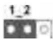

CLRMOS1 allows you to clear the data in CMOS. To clear and reset the system parameters to default setup, please turn off the computer and unplug the power cord from the power supply. After waiting for 15 seconds, use a jumper cap to short pin2 and pin3 on CLRMOS1 for 5 seconds. However, please do not clear the CMOS right after you update the BIOS. If you need to clear the CMOS when you just finish updating the BIOS, you must boot up the system first, and then shut it down before you do the clear-CMOS action. Please be noted that the password, date, time, and user default profile will be cleared only if the CMOS battery is removed.

If you clear the CMOS, the case open may be detected. Please adjust the BIOS option "Clear Status" to clear the record of previous chassis intrusion status.
1.4 Onboard Headers and Connectors

Onboard headers and connectors are NOT jumpers. Do NOT place jumper caps over these headers and connectors. Placing jumper caps over the headers and connectors will cause permanent damage to the motherboard.
System Panel Header
(9-pin PANEL1)
(see p.1, No. 9)
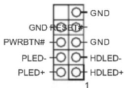
Connect the power switch, reset switch and system status indicator on the chassis to this header according to the pin assignments below. Note the positive and negative pins before connecting the cables.

PWRBTN (Power Switch):
Connect to the power switch on the chassis front panel. You may configure the way to turn off your system using the power switch.
RESET (Reset Switch):
Connect to the reset switch on the chassis front panel. Press the reset switch to restart the computer if the computer freezes and fails to perform a normal restart.
PLED (System Power LED):
Connect to the power status indicator on the chassis front panel. The LED is on when the system is operating. The LED keeps blinking when the system is in S1/S3 sleep state. The LED is off when the system is in S4 sleep state or powered off (S5).
HDLED (Hard Drive Activity LED):
Connect to the hard drive activity LED on the chassis front panel. The LED is on when the hard drive is reading or writing data.
The front panel design may differ by chassis. A front panel module mainly consists of power switch, reset switch, power LED, hard drive activity LED, speaker and etc. When connecting your chassis front panel module to this header, make sure the wire assignments and the pin assignments are matched correctly.
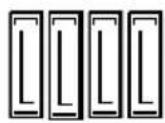
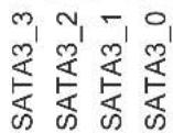
Serial ATA3 Connectors
(SATA3_0:
see p.1, No. 12)
(SATA3_1:
see p.1, No. 13)
(SATA3_2:
see p.1, No. 14)
(SATA3_3:
see p.1, No. 15)

These four SAT
connectors support SATA
data cables for internal
storage devices with up to
6.0 Gb/s data transfer rate.
USB 2.0 Headers
(9-pinUSB_9_10)
(see p.1, No. 6)
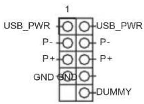
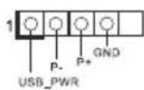
There is one header
and one port on this motherboard. Each U
2.0 header can support two ports.
(4-pinUSB11)
(see p.1, No. 18)
USB 3.0 Header
(19-pin USB3_7_8)
(see p.1, No. 7)

Besides four USB 3.0
ports on the I/O panel, there is one header on this
motherboard. Each USB
3.0 header can support two ports.
Front Panel Audio Header
(9-pin HD_AUDIO1)
(see p.1, No. 17)

This header is for
connecting audio devices
to the front audio panel.

- High Definition Audio supports Jack Sensing, but the panel wire on the chassis must support HDA to function correctly. Please follow the instructions in our manual and chassis manual to install your system.
- If you use an AC'97 audio panel, please install it to the front panel audio header by the steps below:
A. Connect Mic_IN (MIC) to MIC2_L
B. Connect Audio_R (RIN) to OUT2_R and Audio_L (LIN) to OUT2_L.
C. Connect Ground (GND) to Ground (GND).
D. MIC_RET and OUT_RET are for the HD audio panel only. You don't need to connect them for the AC'97 audio panel.
E. To activate the front mic, go to the "FrontMic" Tab in the Realtek Control panel and adjust "Recording Volume".
Chassis Speaker Header (4-pin SPEAKER1) (see p.1, No. 10)

Please connect the chassis speaker to this header.
Chassis Fan Connector (4-pin CHA_FAN1) (see p.1, No. 4)

Please connect fan cables to the fan connector and match the black wire to the ground pin.
CPU Fan Connector (4-pin CPU_FAN1) (see p.1, No.2)

This motherboard provides a 4-Pin CPU fan (Quiet Fan) connector. If you plan to connect a 3-Pin CPU fan, please connect it to Pin 1-3.
ATX Power Connector (24-pin ATXPWR1) (see p.1, No. 5)

This motherboard provides a 24-pin ATX power connector. To use a 20-pin ATX power supply, please plug it along Pin 1 and Pin 13.
ATX 12V Power Connector (4-pin ATX12V1) (see p.1, No. 1)

This motherboard provides an 4-pin ATX 12V power connector.
Chassis Intrusion Header (2-pin CI1) (see p.1, No. 16)

This motherboard supports CASE OPEN detection feature that detects if the chassis cove has been removed. This feature requires a chassis with chassis intrusion detection design.
TPM Header (17-pin TPMS1) (see p.1, No.8)

This connector supports Trusted Platform Module (TPM) system, which can securely store keys, digital certificates, passwords, and data. A TPM system also helps enhance network security, protects digital identities, and ensures platform integrity.
1 Einleitung
Serial-ATA-III-Anschlüsse
(SATA3_0:
siehe S.1,Nr.12)
(SATA3_1:
siehe S.1,Nr.13)
(SATA3_2:
siehe S.1,Nr.14)
(SATA3_3:
siehe S.1,Nr.15)
Ta MaTePnHcKa Hata OeCneuBaet BeiNKoIeHHy IpnOH3BOmTeBHOCTb
I XapaKTePn3yeTcI IPOuHOJ KOHCTpyKUneB COOTBeTCTBNC Tpe6OBaHnA M
KOMIIaHNN ASRock B OTHoIeHHN KaueCTBa N OJIOROBeHuOCTN.

IIO npuune obnoobnue nceuubkaa uHa mapeuncky noamfopmy u npoqpaMnHOO obecneueHuaBIOS codepKumoe hacmoiue dokyemmauu mokeb u3meHo 6e3 npedabapumelbhozo ybedomlenu. Ipu u3meHauu codepKumoo hacmoue zo dokyemma e0 obnoBHeHna bpcur bydem docymna Ha be6-caime ASRock 6e3 npedabapumelbhozo ybedomlenu. Ipu neobxodumocmu mexhueckoi nodepkku, cbaanHou c mapeunckou nlamoi, nocemume be6-caum u naudume Ha hem unboPmaquio o modenu ucnoB3yEmou bamu mapeunckou n lambl. Ha be6-caime ASrock maKe me Kno haui cambu nocedeHui nepeuenb nodepkuaebmx VGA-kapm u II.I Be6-caum ASrock http://www.asrock.com.
1.1 KomnneKT noctabkn
- MaTePuncka IIaTa ASRock B150M-ITX (ΦopM-ΦakTop Mini-ITX)
KpaTKoe pyKOBOCTBO IO yCTaHOBKe ASRock B150M-ITX
-ДиСКсПОДЯASRockB150M-ITX
- 2xKa6eIηpeaunДaHHbIX Serial ATA (SATA) (Прno6peTaIoTcЯОтдьHo)
1xKpaHnHaHeiCnOpTaMn BBOJa-BbBOJa
1.2 Cpeunfkaua
(4-KoHTaKTbI, CHA_FAN1)
(CM. cTp. 1, N 4)

IpeHa3HaueH IJI
IOKIIIOUeHn Ka6eH
pa3bema BcHTnIaTopa I
IOKIIIOUeHn YepHO
IPOBOJa K 3a3eMJIeHNo.
Pa3bem BeHTnIaTopa oxJaXeHn Ipoeccopa
(4-KoHTaKTHbI, CPU_FAN1)
(CM. cTp. 1, N° 2)

3Ta MaTePnHcKa IIaTa
chA6KeHa 4-KoHTaKTHbIM
pa3BeMOM II
MaIOUyMaIeRo BeHTNlTOpa
II.I.EcIN BbI co6HpaeTecB
IOKJIIOuHTb 3-KoHTaKTHbI
BeHTNlTOp OXJaXJdeHn
IPOUeCCopa,IOKJIIOuaTe erO
K KOHTaKTam 1-3.
PLED (Sistem GiC LED'i):
Enabling USB Ports for Windows® 7 Installation
Intel® Braswell and Skylake has removed their support for the Enhanced Host Controller Interface (EHCI - USB2.0) and only kept the eXtensible Host Controller Interface (XHCI - USB3.0). Due to that fact that XHCI is not included in the Windows 7 inbox drivers, users may find it difficult to install Windows 7 operating system because the USB ports on their motherboard won't work. In order for the USB ports to function properly, please create a Windows® 7 installation disk with the Intel® USB 3.0 eXtensible Host Controller (xHCI) drivers packed into the ISO file.
Requirements
- A Windows® 7 installation disk or USB drive
USB 3.0 drivers (included in the ASRock Support CD or website)
A Windows* PC
Win7 USB Patcher (included in the ASRock Support CD or website)
Scenarios
You have an ODD and PS/2 ports:
If there is an optical disc drive, PS/2 ports and PS/2 Keyboard or mouse on your computer, you can skip the instructions below and go ahead to install Windows® 7 OS.
If there is an optical disc drive but no PS/2 ports on your computer, please enable the "PS/2 Simulator" option in UEFI SETUP UTILITY > Advanced > USB Configuration, which allows the USB port to function as a PS/2 port, and then you can install the Windows® 7 OS. Please set PS/S Simulator back to disabled after the installation.
You've got nothing:
If you do not have an optical disc drive, please find another computer and follow the instructions below to create a new ISO file with the "Win7 USB Patcher". Then use the new patched Windows® 7 installation USB drive to install Windows® 7 OS.
Instructions
Step 1
Insert the Windows 7 installation disk or USB drive to your system.
Step 2
Extract the tool (Win7 USB Patcher) and launch it.
Step 3
Select the "Win7 Folder" from Step1 by clicking the red circle as shown as the picture below.

Step 4
Select the "USB Driver Folder" by clicking the red circle as shown as the picture below.
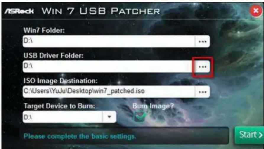
If you are using ASRock's Support CD for the USB 3.0 driver, please select your CD-ROM.
Step 5
Select where to save the ISO file by pressing the red circle as shown as the picture below.

Step 6
If you want to burn the patched image to a CD, please check "Burn Image" and select "Target Device to Burn". If not, the patched ISO image will be exported to the destination selected in Step5. Then Press "Start" to proceed.
Step 7
Now you are able to install Windows® 7 on Braswell or Skylake with the new burned CD. Or please use the patched ISO image to make an OS USB drive to install the OS.
If you need to contact ASRock or want to know more about ASRock, you're welcome to visit ASRock's website at http://www.asrock.com; or you may contact your dealer for further information. For technical questions, please submit a support request form at http://www.asrock.com/support/tsd.asp
ASRock Incorporation
2F., No.37, Sec. 2, Jhongyang S. Rd., Beitou District,
Taipei City 112, Taiwan (R.O.C.)
ASRock EUROPE B.V.
Bijsterhuizen 11-11
6546 AR Nijmegen
The Netherlands
Phone: +31-24-345-44-33
Fax: +31-24-345-44-38
ASRock America, Inc.
13848 Magnolia Ave, Chino, CA91710
U.S.A.
Phone: +1-909-590-8308
Fax: +1-909-590-1026