
XC1140 - Loudspeaker CLARION - Free user manual and instructions
Find the device manual for free XC1140 CLARION in PDF.

| Product Type | Class D Mono Amplifier |
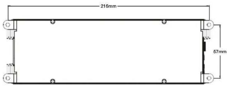
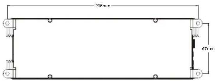
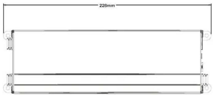
| Dimensions (W x H x D) | 216 x 57 x 226 mm |
| Power Supply | 12 VDC, 30 A fuse (recommended) |
| Output Power (4 ohms) | 210 W x 1 (1% THD+N, CEA-2006A) |
| Output Power (2 ohms) | 350 W x 1 (1% THD+N, CEA-2006A) |
| Frequency Response | < 10 Hz - 250 Hz |
| Low-Pass Filter | -12 dB/octave, selectable 60/90/250 Hz |
| Input Sensitivity | 110 mV - 3.5 V |
| Signal-to-Noise Ratio | > 88.7 dBA (1 W @ 4 ohms) |
| Distortion (THD+N) | < 0.02% |
| Efficiency | 86.3% (4 ohms) |
| Bass EQ | 0 - 12 dB at 45 Hz |
| Built-in Protection | Thermal, short-circuit, low voltage |
| Connections | RCA, high-level input, power and speaker terminals |
| Compatibility | BC2 Remote Level Controller (optional) |
| Maintenance and Cleaning | Clean with a dry cloth. Avoid chemicals. Ensure proper ventilation. |
| Safety | Disconnect the battery before installation. Use appropriate fuses. Do not expose to water. |
| Spare Parts and Repairability | Contact an authorized Clarion dealer for repairs or parts. |
Frequently Asked Questions - XC1140 CLARION
User questions about XC1140 CLARION
0 question about this device. Answer the ones you know or ask your own.
Ask a new question about this device
Download the instructions for your Loudspeaker in PDF format for free! Find your manual XC1140 - CLARION and take your electronic device back in hand. On this page are published all the documents necessary for the use of your device. XC1140 by CLARION.
USER MANUAL XC1140 CLARION
XC1140 and XC1440 Amplifiers
Congratulations on your purchase of a Clarion XC1 Series amplifier. This high speed digital switching amplifier was designed in the United States with sound quality that exceeds that of many conventional Class AB designs while offering stunning efficiency.
When installed and configured properly, this XC1 Series amplifier will bring a new level of realism and impact to your mobile entertainment system. To get the best performance from your amplifier Clarion recommends that you have this amplifier installed and configured by an experienced professional.
ABOUT THE MANUAL AND WARRANTY
This manual describes the basic requirements to install both the XC1140 and XC1440 amplifier. The installation and configuration of these amplifiers can be complex. If you do not possess the necessary knowledge, experience and/or tools to perform this installation please contact your local authorized Clarion dealer to arrange for professional installation. Keep all instructions and your sales receipt for future reference and warranty purposes.
WARNING
Clarion products are capable of producing high sound pressure levels that can damage your hearing and make it difficult for the driver to hear other cars or emergency vehicles. Clarion wants you as a customer for life - please be responsible at all times when enjoying your audio system. Clarion takes no responsibility for any personal injury, loss or damage associated with the use, or misuse of this product. Please refer to the included warranty statement for details.
The Clarion XC1140 amplifier is designed with performance and convenience in mind. Through the use of state-of-the-art signal processing and high speed output devices, this amplifier offers excellent sound quality and dynamics. The XC1140 amplifier incorporates the following features:
• High Speed output devices for dynamic performance
- Pulse Width Modulated MOSFET Power Supply for efficient power delivery
- Remote Turn-On with muting for silent start-up
- Adjustable Low-Pass Electronic Crossover with -12dB/Octave Slope, 60, 90 or 250Hz
- Adjustable input level controls with ground loop isolation
- 2-Ohm load stable
• Corrosion resistant power, speaker and RCA connections
- BC2 Remote subwoofer level control compatible
- Speaker level input Jack included
- Circuit Boards with a conformal coating to resist moisture damage
- Low Profile design with corrosion resistant high efficiency aluminum heat sink
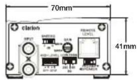
XC1140 CONNECTIONS AND CONTROLS
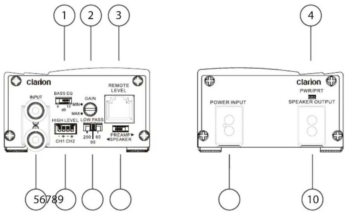
- Bass EQ Switch
- Input Sensitivity Control (Gain)
- BC2 Remote Level Control Connection Jack
- Power/Protection LED
- Input RCA Connection Pigtails
- Speaker Level Input Jack
- Crossover Frequency Selector
- Preamp/Speaker Level input selector
- Power Input Connector Jack
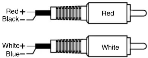
- Output Speaker Wires:
Red: + Output
Black: - Output
The Clarion XC1440 amplifier is designed with performance and convenience in mind. Through the use of state-of-the-art signal processing and high speed output devices, this amplifier offers excellent sound quality and dynamics. The XC1140 amplifier incorporates the following features:
• High Speed output devices for dynamic performance
- Pulse Width Modulated MOSFET Power Supply for efficient power delivery
- Remote Turn-On with muting for silent start-up
- Selectable High-Pass Electronic Crossover with -12dB/Octave Slope - 60/90/Off
- Adjustable input level controls with ground loop isolation
• 2-Ohm load stable
• Bridgeable design (Minimum impedance 4 Ohms)
• Corrosion resistant power, speaker and RCA connections
- Speaker level input RCA Adapters
- Circuit Boards with a conformal coating to resist moisture damage
- Low Profile design with corrosion resistant high efficiency aluminum heat sink
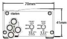
XC1440 CONNECTIONS AND CONTROLS
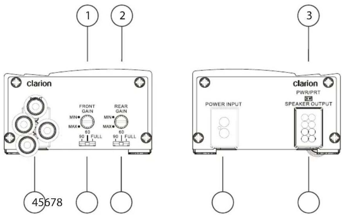
- Front Channel's Input Sensitivity Control (Gain)
- Rear Channel's Input Sensitivity Control (Gain)
- Power/Protection LED
- Input RCA Connection Pigtails
- Front Channel's Crossover Frequency Selector
- Rear Channel's Crossover Frequency Selector
- Power Input Connector Jack
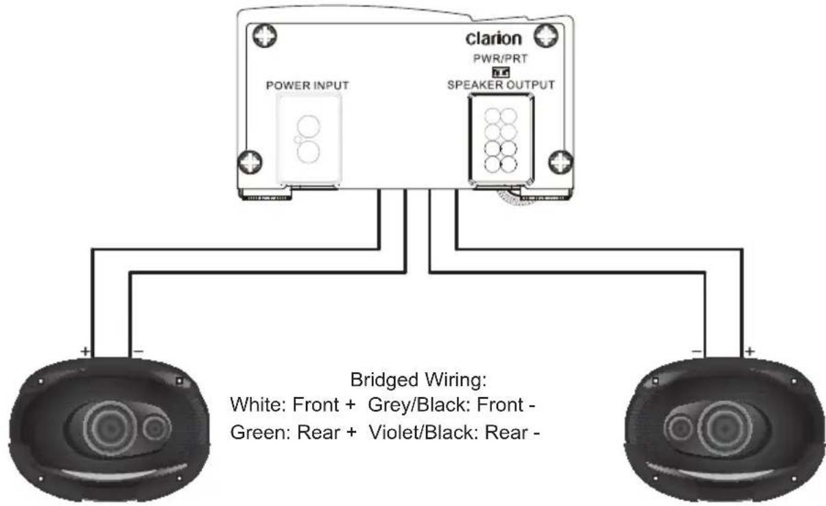
- Output Speaker Wires
White: Left Front + Green: Left Rear +
White/Black: Left Front - Green/Black: Left Rear -
Grey: Right Front + Violet: Right Rear +
Grey/Black: Right Front - Violet/Black: Right Rear -
Sensitivity Control (Gain)
This adjustment is provided to adjust the amplifier sensitivity so that it will produce maximum power given a variety of different input signal voltages. Setting this correctly will ensure that you get maximum performance from your amplifier and is critical to ensuring that minimal noise and distortion is produced.
Clarion recommends the use of an Oscilloscope or distortion detecting device such as the SMD DD-1 or DD-1+ Distortion Detector to properly set amplifier sensitivity. A headroom (gain overlap) setting of 10dB will help to ensure that music that is recorded at low levels can still be reproduced at high volume levels. With this setting, it is the responsibility of the operator to use the amplifier in a manner that will not produce audible distortion. If the end user does not understand why 10dB of gain overlap has been used, please use a lower overlap, 5dB or 0dB to ensure proper system protection.
Procedure (Oscilloscope) Method:
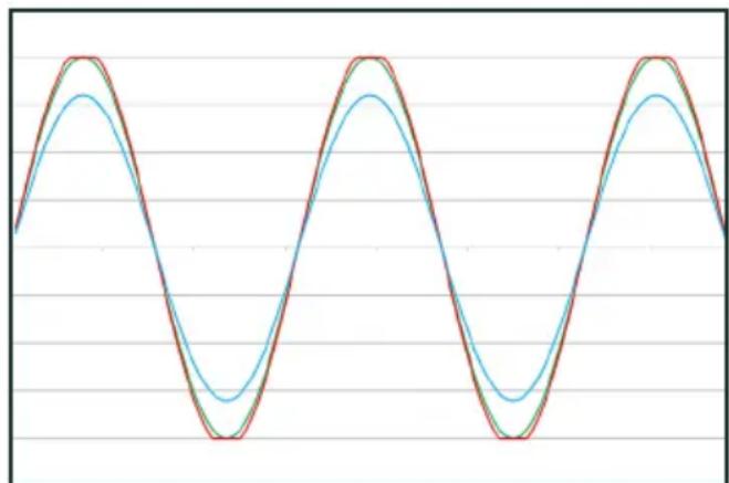
- Obtain a test disc with a selection of Sine Waves recorded at different levels (-10, -5 and 0dB).
- Turn the gain all the way down on the amplifier (to the left).
- Connect the ground terminal of the scope lead to the shield of the RCA cable coming from the source unit. Do no connect this to the speaker output terminals.
- Connect the scope probe to a speaker terminal on the channel you want to adjust.
- Select a Sine wave frequency that is well away from the chosen crossover frequency. For midrange speakers use 1kHz, use 40Hz for subwoofers.
- Turn the source unit up as high as possible without distortion.
- Monitor the output waveform of the amp on the scope.
- Increase the sensitivity of the amplifier until the scope waveform shows a small flat spot on the top or bottom of the waveform. See Figure 2 for an example of what to look for.
line
| Time | Value | |------|-------| | 0 | 0 | | 1 | 1 | | 2 | 0 | | 3 | -1 | | 4 | 0 | | 5 | 1 | | 6 | 0 | | 7 | -1 | | 8 | 0 | | 9 | 1 | | 10 | 0 | | 11 | -1 | | 12 | 0 | | 13 | 1 | | 14 | 0 | | 15 | -1 | | 16 | 0 | | 17 | 1 | | 18 | 0 | | 19 | -1 | | 20 | 0 | | 21 | 1 | | 22 | 0 | | 23 | -1 | | 24 | 0 | | 25 | 1 | | 26 | 0 | | 27 | -1 | | 28 | 0 | | 29 | 1 | | 30 | 0 | | 31 | -1 | | 32 | 0 | | 33 | 1 | | 34 | 0 | | 35 | -1 | | 36 | 0 | | 37 | 1 | | 38 | 0 | | 39 | -1 | | 40 | 0 | | 41 | 1 | | 42 | 0 | | 43 | -1 | | 44 | 0 | | 45 | 1 | | 46 | 0 | | 47 | -1 | | 48 | 0 | | 49 | 1 | | 50 | 0 | | 51 | -1 | | 52 | 0 | | 53 | 1 | | 54 | 0 | | 55 | -1 | | 56 | 0 | | 57 | 1 | | 58 | 0 | | 59 | -1 | | 60 | 0 | | 61 | 1 | | 62 | 0 | | 63 | -1 | | 64 | 0 | | 65 | 1 | | 66 | 0 | | 67 | -1 | | 68 | 0 | | 69 | 1 | | 70 | 0 | | 71 | -1 | | 72 | 0 | | 73 | 1 | | 74 | 0 | | 75 | -1 | | 76 | 0 | | 77 | 1 | | 78 | 0 | | 79 | -1 | | 80 | 0 | | 81 | 1 | | 82 | 0 | | 83 | -1 | | 84 | 0 | | 85 | 1 | | 86 | 0 | | 87 | -1 | | 88 | 0 | | 89 | 1 | | 90 | 0 | | 91 | -1 | | 92 | 0 | | 93 | 1 | | 94 | 0 | | 95 | -1 | | 96 | 0 | | 97 | 1 | | 98 | 0 | | 99 | -1 | | 100 | 0 |Fig 1 - Sine Wave at different Levels
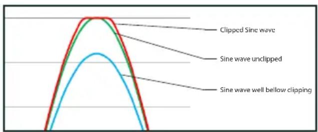
Fig 2 - Close-Up of waveforms
SMD Distortion Detector Method:
- Following the instructions provided with the DD-1 or DD-1+, use the 0dB track to confirm the output of the source unit is unclipped.
- Connect the Distortion Detector to the output of the amplifier and use an appropriate -10dB track. Increase the gain on the amplifier until the Distortion LED illuminates
You should be able to turn the volume up to almost full volume without hearing distortion from your amplifier. If you can't turn the volume up most of the way without distortion, the gains are not set properly.
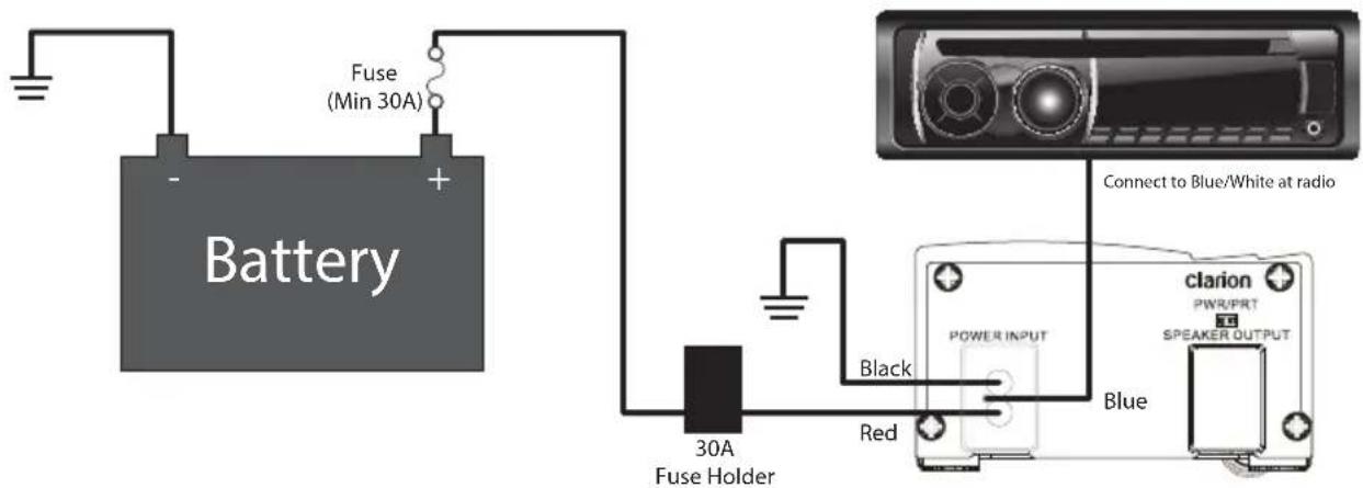
+12V Constant Power Source
This should be connected directly to your battery with a large gauge wire. Clarion recommends at least 8 AWG wire be used. This wire should be protected with a fuse as close as possible to the battery. A water-resistant fuse holder with a minimum 30 Amp fuse is recommended for proper operation.
Remote Turn-On Connection
When +12V is applied to this terminal, the amplifier will turn on. When installing the amplifier with an after market source unit, this wire is typically Blue with a White stripe. Some OEM source units have a wire that behaves similarly.
Ground Connection
This is the most critical connection to be made during the installation of the amplifier. The ground wire should be at least the same gauge as the +12V Constant Power connection. It should be as short as possible and connected to a completely bare metal location on the chassis of the vehicle. All the paint, primer, undercoating or anything else that could hinder current flow must be removed before the ground connection is made. Failure to ensure proper grounding of the amplifier may result in limited performance, noise or other undesirable conditions.
Input RCA Connections
The RCA Input connections should be connected to the RCA Pre-amp outputs of an after market head unit. If you are using a signal source that only has speaker level outputs, adapters are included with each amp. On the XC1140, please connect the Speaker Level input Jack and set the Preamp/
Speaker switch to Speaker. On the XC1440, please use the included RCA pigtails and wire them according to the adjacent image. Note, there are electronic components in these connectors used to attenuate the signal. Do not substitute conventional RCA terminals for these or damage may occur.
Remote Level
The XC1140 amplifier is compatible with the optional BC2 remote subwoofer level control. This control can be mounted in the front of the vehicle to allow the user to adjust the output of the amplifier to match his or her musical tastes. The provided cable should be attached at this point.
Crossover Frequency Control
This adjustment allows the use to alter the -3dB frequency of the crossover. The crossover control is selectable between 60Hz or 90Hz. The XC1140 has a third setting of 250Hz that should be used with a source unit or processor with it's own low-pass filter. To use the XC1440 amplifier for full-range audio, set the Crossover frequency control to "Full"
Power / Protect LED
This LED will illuminate Green when the amp is powered up. In the event that the internal protection circuitry is activated due to a short circuit, over-temperature or low voltage condition, this LED will illuminate Red.
Bass EQ Control
This XC1140 control allows you to add 12dB of boost, centered at 45Hz to the audio signal. This will add impact and depth to the sound of your system. Take caution with this control, as it can dramatically increase the current requirements of your amplifier, drive the amplifier into clipping and may cause damage to your subwoofer(s).
INSTALLATION PLANNING AND CONSIDERATIONS
Clarion XC1 Series amplifiers are designed for installation in vehicles with 12V electrical systems and a common ground configuration. While Clarion strongly recommends professional installation of our products to maximize performance and reliability, installing the amplifier yourself can certainly produce impressive results. Please take into consideration the following when planning your installation.
• Take care in choosing a mounting location for the amplifier. Clarion does not recommend mounting an amplifier to a subwoofer enclosure. Vibrations could damage internal components of the amplifier.
- Ensure the screws used to mount the amplifier will not damage anything underneath the mounting location. This can include interconnects and speaker wires, factory wiring harnesses, computer modules, factory fluid lines, fuel tanks and more. Mounting hardware should be sufficient to ensure the amp will not come loose in the event of a vehicle accident.
- All wiring running to and from the amplifier should be planned so that it's route does not bring it in proximity of any high current devices or computer modules. This will help prevent noise from being induced into the audio system.
- XC1 amplifiers incorporate balanced differential inputs. As such, Clarion recommends the use of twisted pair interconnects to ensure the signal on the center pin and shield of the interconnect allow this circuitry to perform to the best of its ability in terms of rejecting unwanted noise.
- Although Clarion XC1 amplifiers are suitable for marine installations, they are not water resistant. They should be mounted in a dry, well-ventilated location. The marine features of the amp are designed to handle humid conditions commonly associated with installations in boats.
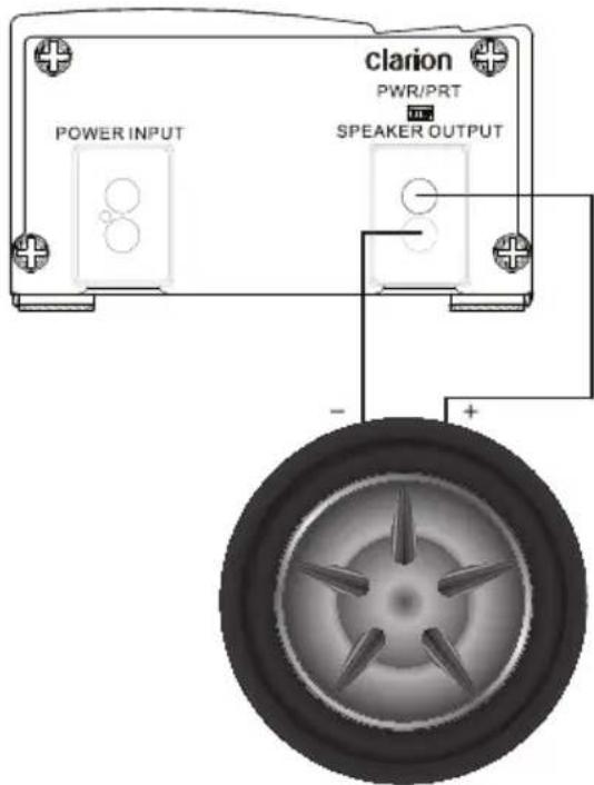
Speaker Connections
The XC1140 amplifier is capable of driving a reactive load with a minimum nominal impedance of 2 Ohms. Clarion recommends the use of at least 12 AWG wire to connect your subwoofer(s).
One 2 Ohm Coil Subwoofer
One Dual 4 Ohm Coil Subwoofer
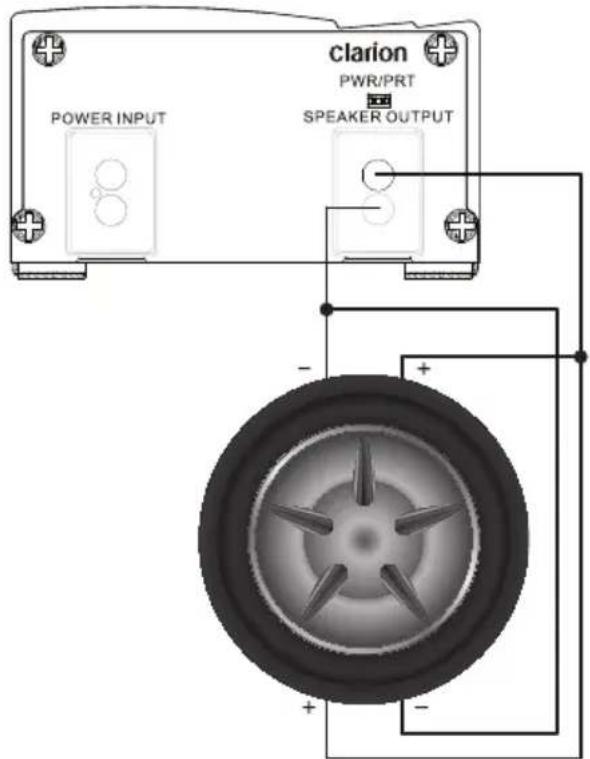
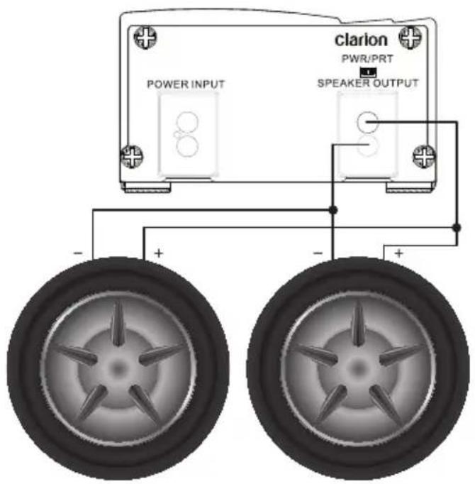
Speaker Wiring Diagrams Continued
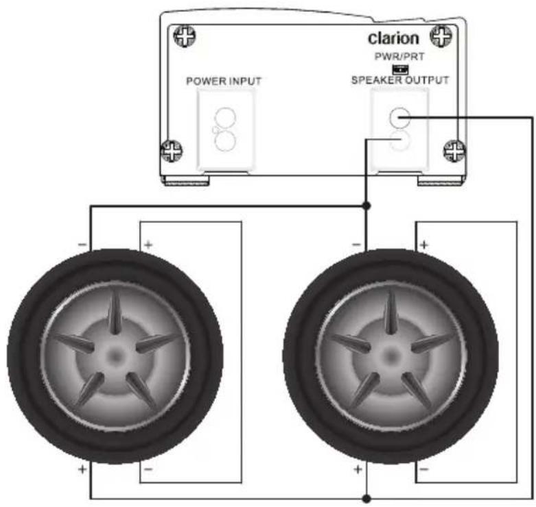
Two Single 4 Ohm Voice Coil Subwoofers
Two Dual 2 Ohm Voice Coil Subwoofers
Speaker Connections
The XC1440 amplifier is capable of driving reactive loads with a minimum nominal impedance of 2 Ohms per channel. Clarion recommends the use of at least 18 AWG wire to connect your speakers.
4 Ohm per channel - 4 Channel Stereo
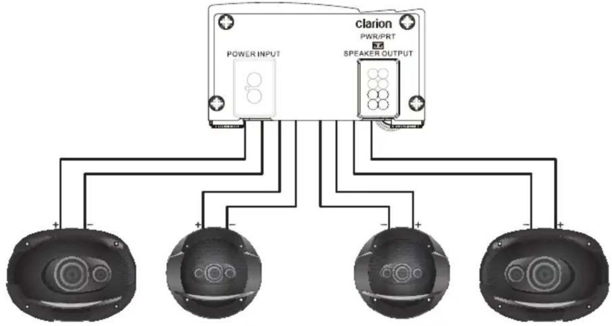
flowchart
graph TD
    A["POWER INPUT"] --> B["Clarion"]
    C["SPEAKER OUTPUT"] --> B
    D["Speaker 1"] --> B
    E["Speaker 2"] --> B
    F["Speaker 3"] --> B
    G["Speaker 4"] --> B
2 Ohms per channel - 4 Channel Stereo
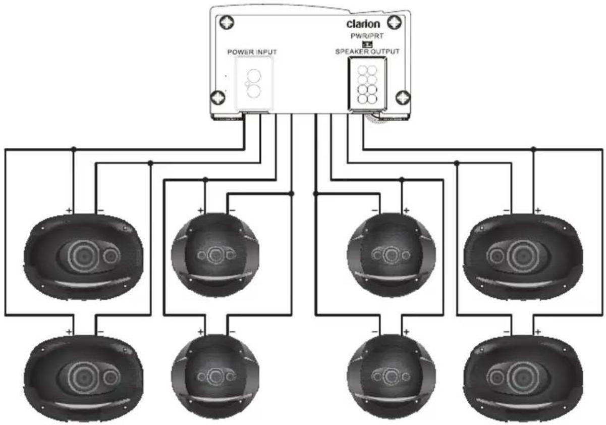
flowchart
graph TD
    A["POWER INPUT"] --> B["Clarion"]
    C["SPEAKER OUTPUT"] --> B
    B --> D1["Speaker 1"]
    B --> D2["Speaker 2"]
    B --> D3["Speaker 3"]
    B --> D4["Speaker 4"]
    B --> D5["Speaker 5"]
    B --> D6["Speaker 6"]
    B --> D7["Speaker 7"]
4 Ohms Bridged
Power Connections
Your amplifier can only produce power if it is fed power efficiently. Clarion recommends the use of at least 8 AWG wire for power and ground connections. Clarion also recommends performing “The Big Three” upgrade to your electrical system when any high power amplifier is being installed. This includes upgrading the power wire between your battery and the alternator for both positive and ground connections, as well as the ground connection between the battery and the chassis and/or rear ground location.
The amplifier ground connection is the most important in terms of the reliable and efficient operation of your amplifier. This connection should be made to a solid and secure point on the vehicle chassis, or directly to the battery. Do not use a seat or seatbelt bolt as a ground location. All of the sound deadening, paint and primer should be removed from the chosen ground location and the wire should be secured with a bolt and locking fastener.
Wiring Precautions
Read all of the wiring precautions prior to making any connections. If you are unsure and/or don't have the necessary installation hardware, contact your local Clarion dealer to perform the installation.
- Before you begin the installation, make sure the vehicle is not running and is in the OFF position.
- Disconnect the negative (-) lead of the battery (or batteries) before making any power connections.
- When making connections, be sure that each connection is clean and secure.
- Insulate all connections with heat shrink tubing where possible.
- A fuse holder and fuse must be installed on the lead coming from the positive (+) terminal of the battery. This fuse should be located as close a possible to the battery terminal for maximum protection. Clarion does not recommend the use of a circuit breaker as a protection device.
- The battery fuse rating should equal the total current consumption at full output of the amplifier(s) connected to that wire. Do not install the fuse until the entire installation has been completed.
- When replacing the amplifier or power wire fuse, always use one having the same amperage rating. Substituting a higher rating fuse or a slow-blow type can result in serious damage to the amplifier or vehicle.
- When creating passage holes for power wire, interconnect cables and speaker wires, use grommets and wire loom to eliminate any sharp edges created during drilling. This will protect the wire from being damaged and help to prevent a short circuit.
Installation
- Locate the amplifier and mark the mounting hole locations.
- Remove the amp and pre-drill the mounting holes.
- Replace the amplifier and secure with adequate hardware.
- Make all the power, signal and speaker connections to the amp.
- Complete the remainder of the installation and finish tuning the amplifier and system.
| Problem Solution | |
| Amplifier will not turn on - Power LED off or Red | - Using a digital multi-meter, check for 12V at the +12V and REM Connection relative to the ground connection.- Fuse at the battery or amplifier is blown. Inspect and replace as required. |
| Audio stops playing - Thermal protection circuit has shut down amp to protect the circuitry. Ensure there is adequate ventilation around the amplifier.- Fuse at the battery or amplifier is blown. Inspect and replace as required.- Amplifier is loaded below 2 Ohms per channel (4 Ohms bridged mono on the XC1440). Check wiring and reconfigure as required. | |
| Amp shuts off at high volumes | - Amplifier may not be getting enough power from your vehicle's electrical system. Ensure that during operation, the voltage at the amplifier does not drop below 10V. Clarion recommends at least 8 AWG power wire for both +12V and GND connections. |
| Distorted Audio - Input gain is not set properly. Adjust as per instructions.- Source signal is distorted. Reduce source output level.- Speaker is damaged. Replace as required. | |
| Less bass than expected | - One speaker or subwoofer may be wired in reverse polarity. Switch the + and - leads.- Crossover may be set too low. Adjust to higher frequency. |
| Fuse Blows - Amplifier output may be shorted. Check all wiring.- Amplifier may be damaged. Remove all speaker wires and check functionality. If the fuse blows with no speakers connectioned, send the amplifier to Clarion for repair. | |
| Whining or ticking noise | - The amplifier may be picking up electrical noise that is traveling on the ground shield of the interconnect.1. Check for solid ground connections at the source unit and amplifier.2. Run a ground wire from the amplifier to the source unit.3. Re-route the interconnect cables away from sources of electrical noise. Ensure you are using good quality shielded interconnects.- The speaker wire or a passive crossover network may be picking up electrical noise. Reroute wiring as required. |
Frequency Response: <10Hz to 250Hz
4 Ohm Power Output (CEA-2006A) 210W x 1 @ <1.0% THD
2 Ohm Power Output (CEA-2006A) 350W x 1 @ <1.0% THD
Signal to Noise Ratio (CEA-2006A) @ 1W/4 Ohms > -88.7 dBA
THD+N at Max Power 4 Ohms < 0.02%
Efficiency at Full Power (4 Ohms) 86.3%
Input Sensitivity (RCA Preamp) 110mV to 3.5V
Input Sensitivity (Speaker Level) 1.5V to <20V
Crossover Frequencies 60Hz, 90Hz to 250Hz
Crossover Slope -12dB/Octave LPF

Frequency Response: <10Hz to >30kHz
4 Ohm Power Output (CEA-2006A) 50W x 4 @ <1.0% THD
2 Ohm Power Output (CEA-2006A) 85W x 4 @ <1.0% THD
Bridged 4 Ohm Power (CEA-2006A) 180W x 2 @ <1.0% THD
Signal to Noise Ratio (CEA-2006A) @ 1W/4 Ohms > -84.9 dBA
THD+N at Max Power 2 Ohms < 0.08%
Efficiency at Full Power (4 Ohms) 81.8%
Input Sensitivity 250mV to 4.1V
Crossover Frequencies 60Hz, 90Hz or OFF
Crossover Slope -12dB/Octave HPF
LIMITED WARRANTY
This Clarion product, when purchased from AND installed by an authorized Clarion dealer in good standing, is warranted against defects in materials and workmanship for a two (2) year period from the date of original purchase.
All Clarion cables, wires and other accessories, if purchased from an authorized Clarion dealer are warranted against defects in materials and workmanship for ninety (90) days from the date of original purchase.
ALL PURCHASES OF CLARION PRODUCTS FROM NON-AUTHORIZED CLARION DEALERS ARE SUBJECT TO FURTHER WARRANTY RESTRICTIONS AS DESCRIBED BELOW.
The conditions of this Limited Warranty and the extent of responsibility of Clarion Corporation of America and Clarion Canada Incorporated (“Clarion”) under this Limited Warranty are as follows:
- IN THE CASE OF THE TWO (2) YEAR LIMITED WARRANTY FOR CLARION PRODUCTS, PROOF OF DATE OF PURCHASE AND PROOF OF INSTALLATION BY AN AUTHORIZED CLARION DEALER IS REQUIRED.
- This Limited Warranty will become void if service performed by anyone other than an approved Clarion Warranty Service Center results in damage to the products.
- This Limited Warranty does not apply to any product which has been subject to misuse, neglect or accident, or which has had the serial number altered, defaced or removed, or which has been connected, installed, adjusted, operated or repaired, other than in accordance with the instructions furnished by Clarion. This Limited Warranty does not cover static, noise or other electrical interferences or labor costs for the removal or re-installation of the unit for repair.
- The sole responsibility of Clarion under this Limited Warranty shall be limited to the repair of the products or replacement of the product, at the sole discretion of Clarion.
- Product must be shipped in its original carton or equivalent carton, fully insured, with shipping charges prepaid. Clarion will not assume any responsibility for any loss or damage incurred in shipping.
- CLARION PRODUCTS PURCHASED FROM A SOURCE OTHER THAN AN AUTHORIZED CLARION DEALER, INCLUDING ANY AND ALL PURCHASES VIA THE INTERNET FROM A NON INTERNET AUTHORIZED CLARION DEALER, SHALL NOT BE COVERED BY ANY CLARION LIMITED WARRANTY TO THE EXTENT ALLOWED BY APPLICABLE LAW. IN THE EVENT AND TO THE EXTENT APPLICABLE LAW PROHIBITS ELIMINATION OF WARRANTIES UNDER THESE CIRCUMSTANCES, THE APPLICABLE LIMITED WARRANTY PERIOD SHALL BE DEEMED TO BE FIFTEEN (15) DAYS FROM THE DATE OF ORIGINAL PURCHASE.
- ALL IMPLIED WARRANTIES EXCEPT TO THE EXTENT PROHIBITED BY APPLICABLE LAW SHALL HAVE NO GREATER DURATION THAN THE WARRANTY PERIOD SET FORTH ABOVE. UNDER NO CIRCUMSTANCES SHALL CLARION BE LIABLE FOR ANY LOSS OR DAMAGE, DIRECT OR CONSEQUENTIAL, ARISING OUT OF THE USE OR INABILITY TO USE THE PRODUCT. BECAUSE SOME STATES DO NOT ALLOW LIMITATIONS ON HOW LONG AN IMPLIED WARRANTY LASTS OR EXCLUSIONS OR LIMITATIONS OF INCIDENTAL OR CONSEQUENTIAL DAMAGES, THE ABOVE LIMITATIONS OR EXCLUSIONS MAY NOT APPLY TO YOU.
- THIS LIMITED WARRANTY GIVES YOU SPECIFIC LEGAL RIGHTS, AND YOU MAY ALSO HAVE OTHER RIGHTS WHICH VARY FROM STATE TO STATE.
- The laws of the State of California shall govern and control this limited warranty, its interpretation and enforcement.
MERCI
This Clarion product, when purchased from AND installed by an authorized Clarion dealer in good standing, is warranted against defects in materials and workmanship for a two (2) year period from the date of original purchase.
All Clarion cables, wires and other accessories, if purchased from an authorized Clarion dealer are warranted against defects in materials and workmanship for ninety (90) days from the date of original purchase.
ALL PURCHASES OF CLARION PRODUCTS FROM NON-AUTHORIZED CLARION DEALERS ARE SUBJECT TO FURTHER WARRANTY RESTRICTIONS AS DESCRIBED BELOW.
The conditions of this Limited Warranty and the extent of responsibility of Clarion Corporation of America and Clarion Canada Incorporated (“Clarion”) under this Limited Warranty are as follows:
- IN THE CASE OF THE TWO (2) YEAR LIMITED WARRANTY FOR CLARION PRODUCTS, PROOF OF DATE OF PURCHASE AND PROOF OF INSTALLATION BY AN AUTHORIZED CLARION DEALER IS REQUIRED.
- This Limited Warranty will become void if service performed by anyone other than an approved Clarion Warranty Service Center results in damage to the products.
- This Limited Warranty does not apply to any product which has been subject to misuse, neglect or accident, or which has had the serial number altered, defaced or removed, or which has been connected, installed, adjusted, operated or repaired, other than in accordance with the instructions furnished by Clarion.
This Limited Warranty does not cover static, noise or other electrical interferences or labor costs for the removal or re-installation of the unit for repair. - The sole responsibility of Clarion under this Limited Warranty shall be limited to the repair of the products or replacement of the product, at the sole discretion of Clarion.
- Product must be shipped in its original carton or equivalent carton, fully insured, with shipping charges prepaid. Clarion will not assume any responsibility for any loss or damage incurred in shipping.
- CLARION PRODUCTS PURCHASED FROM A SOURCE OTHER THAN AN AUTHORIZED CLARION DEALER, INCLUDING ANY AND ALL PURCHASES VIA THE INTERNET FROM A NON INTERNET AUTHORIZED CLARION DEALER, SHALL NOT BE COVERED BY ANY CLARION LIMITED WARRANTY TO THE EXTENT ALLOWED BY APPLICABLE LAW. IN THE EVENT AND TO THE EXTENT APPLICABLE LAW PROHIBITS ELIMINATION OF WARRANTIES UNDER THESE CIRCUMSTANCES, THE APPLICABLE LIMITED WARRANTY PERIOD SHALL BE DEEMED TO BE FIFTEEN (15) DAYS FROM THE DATE OF ORIGINAL PURCHASE.
- ALL IMPLIED WARRANTIES EXCEPT TO THE EXTENT PROHIBITED BY APPLICABLE LAW SHALL HAVE NO GREATER DURATION THAN THE WARRANTY PERIOD SET FORTH ABOVE. UNDER NO CIRCUMSTANCES SHALL CLARION BE LIABLE FOR ANY LOSS OR DAMAGE, DIRECT OR CONSEQUENTIAL, ARISING OUT OF THE USE OR INABILITY TO USE THE PRODUCT. BECAUSE SOME STATES DO NOT ALLOW LIMITATIONS ON HOW LONG AN IMPLIED WARRANTY LASTS OR EXCLUSIONS OR LIMITATIONS OF INCIDENTAL OR CONSEQUENTIAL DAMAGES, THE ABOVE LIMITATIONS OR EXCLUSIONS MAY NOT APPLY TO YOU.
- THIS LIMITED WARRANTY GIVES YOU SPECIFIC LEGAL RIGHTS, AND YOU MAY ALSO HAVE OTHER RIGHTS WHICH VARY FROM STATE TO STATE.
- The laws of the State of California shall govern and control this limited warranty, its interpretation and enforcement.
Clarion Canada Inc.
All Rights Reserved. Copyright 2015 Clarion Canada Inc.
Printed in China


- ABOUT THE MANUAL AND WARRANTY
- WARNING
- Sensitivity Control (Gain)
- Procedure (Oscilloscope) Method:
- SMD Distortion Detector Method:
- +12V Constant Power Source
- Remote Turn-On Connection
- Ground Connection
- Input RCA Connections
- Remote Level
- Crossover Frequency Control
- Power / Protect LED
- Bass EQ Control
- INSTALLATION PLANNING AND CONSIDERATIONS
- Speaker Connections
- One 2 Ohm Coil Subwoofer
- One Dual 4 Ohm Coil Subwoofer
- Speaker Wiring Diagrams Continued
- Ohm per channel - 4 Channel Stereo
- Ohms per channel - 4 Channel Stereo
- Ohms Bridged
- Power Connections
- Wiring Precautions
- Installation
- LIMITED WARRANTY
- MERCI
- Clarion Canada Inc.
Brand : CLARION
Model : XC1140
Category : Loudspeaker