
RNAB081J1JBRG - Ice machine FRIGIDAIRE - Free user manual and instructions
Find the device manual for free RNAB081J1JBRG FRIGIDAIRE in PDF.
| Product Type | Automatic ice maker for refrigerator |
| Brand | Frigidaire |
| Model | RNAB081J1JBRG |
| Power Supply | 120 V (US standard) |
| Required Water Pressure | 30 to 100 psi (137.9 to 827.3 kPa) |
| Recommended Supply Line | Copper, 6.4 mm (1/4 in.) outside diameter |
| Connection | Brass compression nut and ferrule 6.4 mm (1/4 in.) |
| Shut-off Valve Type | Manual valve (do not use self-piercing valve) |
| Operation | Automatic with On/Off paddle |
| Automatic Shut-off | Yes, when bin is full |
| Time to First Production | Approximately 24 hours |
| Ice Bin Cleaning | With warm soapy water, rinse and dry – do not put in dishwasher |
| Extended Shutdown | Close water supply valve |
| Included Parts | Ice maker, bin, plastic supply tube, gasket, clamps, water valve, screws, leveling bracket |
| Installation Tools Required | Putty knife, Phillips screwdriver, 1/4 in. wrench, needle-nose pliers, adjustable wrench, drill |
| Warning | Connect only to a potable water source |
| Minimum Temperature | Do not install plastic tubing in areas where temperature drops below freezing |
| Water Softener | Do not connect to a softened water supply |
Frequently Asked Questions - RNAB081J1JBRG FRIGIDAIRE
User questions about RNAB081J1JBRG FRIGIDAIRE
0 question about this device. Answer the ones you know or ask your own.
Ask a new question about this device
Download the instructions for your Ice machine in PDF format for free! Find your manual RNAB081J1JBRG - FRIGIDAIRE and take your electronic device back in hand. On this page are published all the documents necessary for the use of your device. RNAB081J1JBRG by FRIGIDAIRE.
USER MANUAL RNAB081J1JBRG FRIGIDAIRE
AUTOMATIC ICE MAKER INSTALLATION INSTRUCTIONS

WARNING
Ice maker kit should be installed only by an authorized service technician.

WARNING
- To avoid electric shock, which can cause death or severe personal injury, disconnect the refrigerator from electrical power before connecting a water supply line to the refrigerator.
- Connect the ice maker to a potable water supply only.

CAUTION
To Avoid Property Damage:
- Copper tubing is recommended for the water supply line. Water supply tubing made of 14 inch plastic should not be used since it greatly increases the potential for water leaks. The manufacturer will not be responsible for any damage if plastic tubing is used for the supply line.
- DO NOT install water supply tubing in areas where temperatures fall below freezing.
- Chemicals from a malfunctioning water softener can damage the ice maker. If the ice maker is connected to softened water, ensure that the softener is maintained and working properly.
The following items will be required to install the ice maker kit:
- 14 inch copper supply line with shut off valve
- 14 inch brass compression nut and ferrule
- Freezer shelf (Some models not equipped with shelf). If your model does not have one, contact your dealer to order one.
The copper tubing and shut off valve are available in a kit from your local hardware or plumbing supply store. Coil enough tubing at the back of the unit to allow movement for cleaning.
natural_image
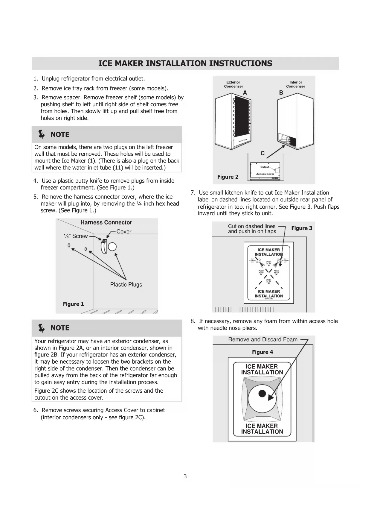
Technical line drawing of a mechanical device with internal components (no text or symbols)Use This Page to Identify Parts
natural_image
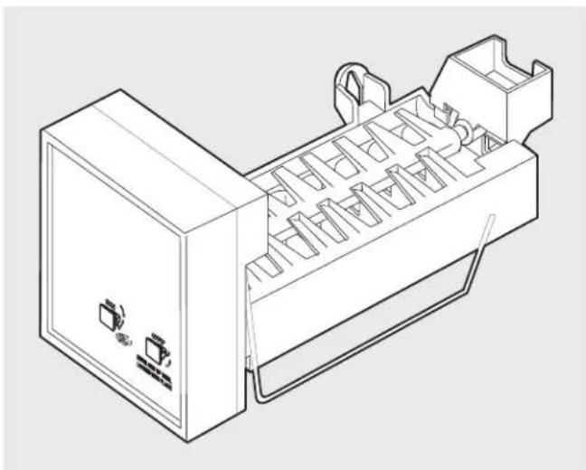
Technical line drawing of a mechanical component with no visible text or symbols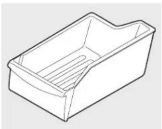
natural_image
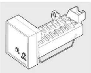
Line drawing of a rectangular plastic container with internal slots (no text or symbols)
natural_image
Two identical wireCoiled hoses with connectors, labeled 'OR' on the left (no text or symbols on the hoses themselves)- Ice Maker 2. Ice Container 3. Plastic Water Supply Tubing
natural_image
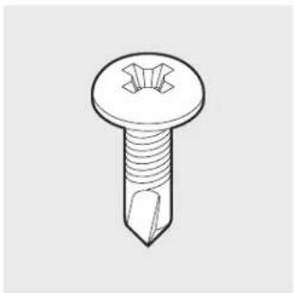
Line drawing of a screw with a pointed tip and threaded shaft (no text or symbols)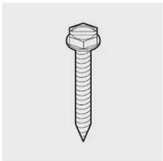
natural_image
Line drawing of a hexagonal bolt with threaded shaft (no text or symbols)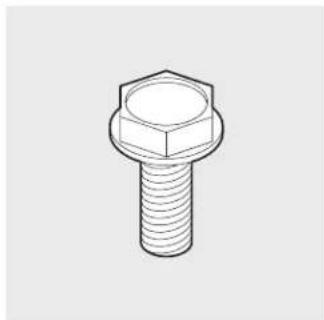
natural_image
Line drawing of a hexagonal bolt with threaded shaft (no text or symbols)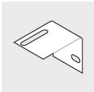
natural_image
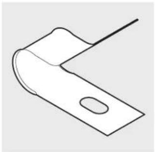
Simple line drawing of a folded paper or metal bracket with two slots (no text or symbols)- Screws - Qty 2 5. Screws - Qty 2 7. Leveling Bracket - Qty 16. Leveling Bracket Screw -
Qty 1
natural_image
Simple line drawing of a bent metal bracket with a slot (no text or symbols)
natural_image
Isometric line drawing of a mechanical clamp or bracket (no text or symbols)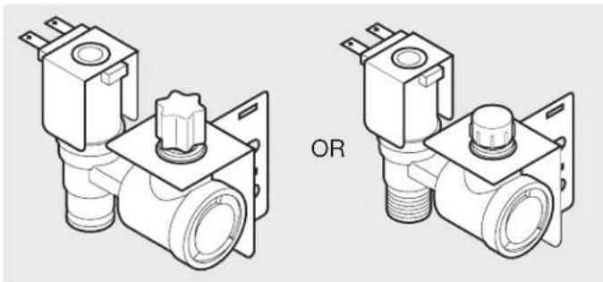
natural_image
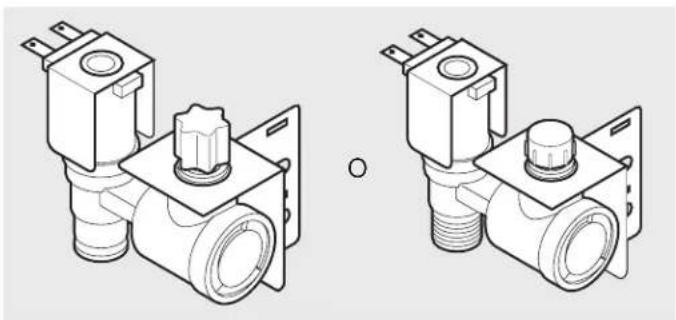
Technical line drawing of two identical mechanical valve assemblies with no text or symbols- Steel Clamp - Qty 1 10. Water Valves - Qty 19. Plastic Clamp - Qty 2
natural_image
Line drawing of a mechanical tool or rod with a flanged end and central hub (no text or symbols)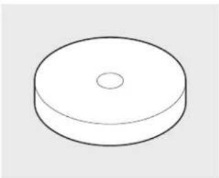
natural_image
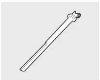
Simple line drawing of a circular object with a central hole (no text or symbols)- Tube Seal - Qty 111. Water Inlet Tube - Qty 1
| Tools Required: | |
| • Plastic Putty Knife • Phillips | TM Screwdriver |
| • 1⁄4 inch Socket Wrench or Nut Driver • Needle Nose Pliers | |
| • Adjustable Wrench • Power Drill with Phillips | TM bit |
| • Small Kitchen Knife | |
ICE MAKER INSTALLATION INSTRUCTIONS
- Unplug refrigerator from electrical outlet.
- Remove ice tray rack from freezer (some models).
- Remove spacer. Remove freezer shelf (some models) by pushing shelf to left until right side of shelf comes free from holes. Then slowly lift up and pull shelf free from holes on right side.

NOTE
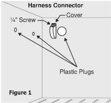
On some models, there are two plugs on the left freezer wall that must be removed. These holes will be used to mount the Ice Maker (1). (There is also a plug on the back wall where the water inlet tube (11) will be inserted.)
- Use a plastic putty knife to remove plugs from inside freezer compartment. (See Figure 1.)
- Remove the harness connector cover, where the ice maker will plug into, by removing the 14 inch hex head screw. (See Figure 1.)

NOTE
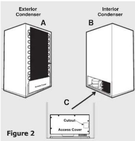
Your refrigerator may have an exterior condenser, as shown in Figure 2A, or an interior condenser, shown in figure 2B. If your refrigerator has an exterior condenser, it may be necessary to loosen the two brackets on the right side of the condenser. Then the condenser can be pulled away from the back of the refrigerator far enough to gain easy entry during the installation process.
Figure 2C shows the location of the screws and the cutout on the access cover.
- Remove screws securing Access Cover to cabinet (interior condensers only - see figure 2C).
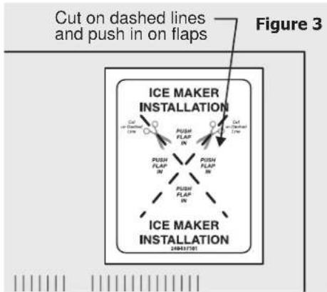
- Use small kitchen knife to cut Ice Maker Installation label on dashed lines located on outside rear panel of refrigerator in top, right corner. See Figure 3. Push flaps inward until they stick to unit.
flowchart
graph TD
    A["Cut on dashed lines and push in on flaps"] --> B["PUSH FLAP IN"]
    A --> C["PUSH FLAP IN"]
    A --> D["PUSH FLAP IN"]
    B --> E["ICEMAKER INSTALLATION"]
    C --> E
    D --> E
    E --> F["24043781"]
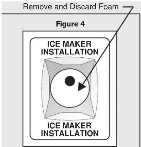
- If necessary, remove any foam from within access hole with needle nose pliers.
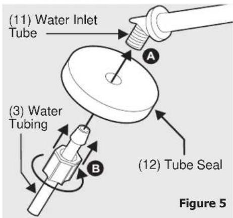
- Push tube seal (12) over threads (Figure 5). Push plastic water supply tubing (3) into water inlet tube (11) as far as it will go and finger tighten nylon compression nut onto threaded end of inlet tube. Tighten another 12 turn with a wrench. DO NOT over-tighten.
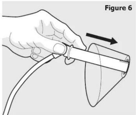
- Push water inlet tube (11) through small hole where Installation label was (Figure 6). Rotate while inserting tube until flat surface of inlet tube is tight against back of refrigerator.
natural_image
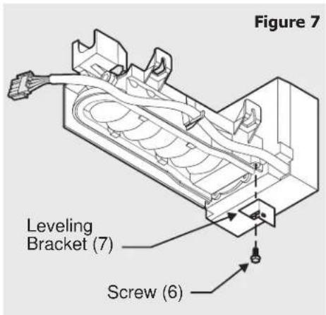
Illustration of a hand holding a cylindrical device with a curved arrow indicating rotation (no text or symbols)- Install adjustable leveling bracket (7) on bottom of Ice Maker (1) with screw (6) (Figure 7). DO NOT tighten bracket. It will be tightened later in this procedure.
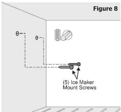
- Start two, long, Ice Maker mounting screws (5) into freezer wall where plugs were removed in Step 4. Turn each screw clockwise five turns (Figure 8).

NOTE
It requires the use of both hands to hook up and secure the Ice Maker to the freezer wall. DO NOT let the Ice Maker dangle free after the wiring harness is plugged into the connector on the back freezer wall.
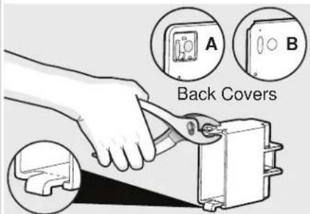
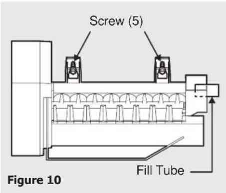
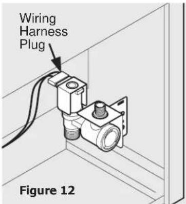
- Connect wiring harness into connector mounted on the back freezer panel, just to the left of where the water inlet tube comes through. The harness connector is keyed so it will only fit one way. Next, slide Ice Maker connector cover over connector, noting the orientation in Figure 9. (Snap on top, hook on bottom). The Ice maker connector cover can then be snapped into place into the back panel or slid up tight to back panel depending on which version of back panel you have (see note below). Then, mount Ice Maker to the two screws (5) you started earlier from Step 12. (See figure 10.) Tighten screws. Make sure water inlet tube (11) is sitting inside fill cup.
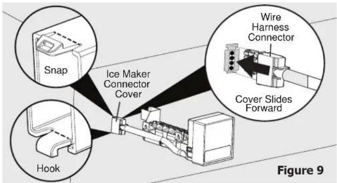

NOTE
If your back cover looks like (A) proceed to installing ice maker. If your back cover looks like (B), break off snap and hook on connector cover using pliers, then proceed to installing ice maker.
-
Adjust leveling bracket (7) on Ice Maker (1). When the gap between freezer wall and Ice Maker is the same at top and bottom, then Ice Maker is level. Tighten screw (6) when level.
-
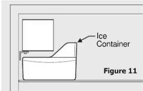
Reinstall freezer shelf in lower position. Set ice container (2) on shelf.
- Connect wiring harness to water valve. Make sure connection is tight.

NOTE
If your refrigerator has an interior condenser, it's a good idea to connect the plastic water supply tubing and the wiring harness to the water valve prior to mounting the valve to the rear panel because of space constraints. Once the valve is mounted, it's very hard to get your hands in there to make the necessary connections. Additionally, the metal tubing may have to be bent slightly out of the way for the water valve to fit in the space. Do Not kink tubing.
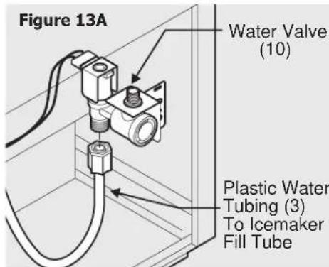
- Two types of water valves can be used with this kit. Follow the instructions which applies to the type of valve supplied with your kit. See Figures 13A and 13B. For valves with a threaded outlet (Figure 13A), push the bullet-shaped end of the green tube into the valve and tighten the plastic nut (finger tight). Then tighten it an additional 12 turn with a wrench. DO NOT overtighten.
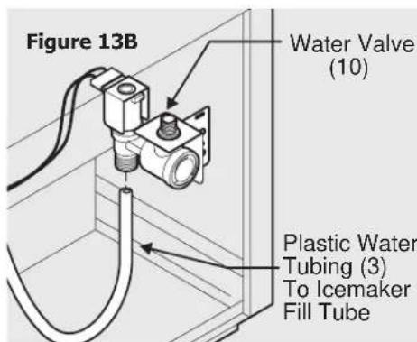
For valves with a push-in connection with no threads (Figure 13B), check the green hose to see if it has a small black mark near the end without the formed tip and plastic nut. If there is not a mark, use a measuring tape and marker to place a mark 11/16 inch from the end. The valve seals against the outside surface of the tube with an o-ring, so be sure the end of the tube is clean and not scratched. Grasp the tube just above the mark and push it firmly into the valve until it bottoms out. When pushed in to the proper depth, the mark will line up with the end of the valve fitting. If the mark is not even with the end of the fitting, the tube is not pushed in all the way. To remove the tube, push inward on the collar at the end of the fitting while pulling on the tube.
- Locate factory drilled holes at bottom right corner of rear panel. Align water valve bracket with factory drilled holes. You may have to bend the metal tubing slightly out of the way. Use a power drill with a Phillips® head bit to drive two self tapping screws (4) through bracket and into cabinet.
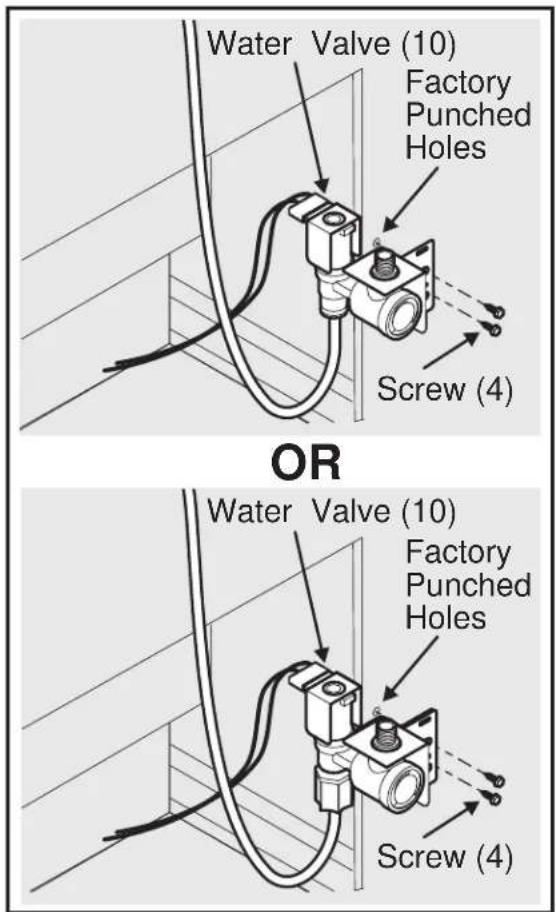
Figure 14

NOTE
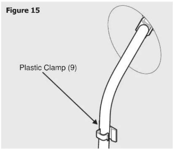
Clean back of cabinet with a commercial household cleaner, ammonia or alcohol before applying plastic clamps to water tubing.
- Secure plastic water tubing to rear of cabinet with two plastic clamps (9).
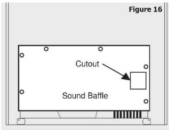
- Punch out cutout on access cover to allow for water valve (interior condenser models only).
- Remount access cover (interior condenser models only) and condenser, if it was pulled out of the way because of space constraints.
Connecting Ice Maker to Water Supply

WARNING
Ice maker kit should be installed only by an authorized service technician.

WARNING
- To avoid electric shock, which can cause death or severe personal injury, disconnect the refrigerator from electrical power before connecting a water supply line to the refrigerator.
- Connect the ice maker to a potable water supply only.

IMPORTANT
Ensure that your water supply line connections comply with all local plumbing codes.
Before Installing The Water Supply Line, You Will Need:
Basic tools: adjustable wrench, 14 inch nut driver, and Phillips ™ screwdriver.
- Access to a household cold water line with water pressure between 30 and 100 psi. (2 and 6.9 bar)
- A water supply line made of 14 inch (6.4 mm) OD, copper tubing. To determine the length of copper tubing needed, you will need to measure the distance from the ice maker inlet valve at the back of the refrigerator to your cold water pipe. Then add approximately 7 feet (2.1 meters), so the refrigerator can be moved out for cleaning.
- A shutoff valve to connect the water supply line to your household water system. DO NOT use a self-piercing type shutoff valve.
- A compression nut and ferrule (sleeve) for connecting the water supply line to the ice maker inlet valve.
To Connect Water Supply Line To Ice Maker Inlet Valve
- Disconnect refrigerator from electric power supply.
- Place end of water supply line into sink or bucket. Turn ON water supply and flush supply line until water is clear. Turn OFF water supply at shutoff valve.
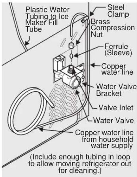
- Remove plastic cap from water valve inlet and discard cap.
- Slide brass compression nut, then ferrule (sleeve), onto water supply line, as shown.
-
Push water supply line into water valve inlet as far as it will go (¼ inch). Slide ferrule (sleeve) into valve inlet and finger tighten compression nut onto valve. Tighten another half turn with a wrench; DO NOT over tighten.
-
With steel clamp and screw, secure water supply line to rear panel of refrigerator at location as shown.
- Coil excess water supply line (about 2 ½ turns) behind refrigerator as shown and arrange coils so they do not vibrate or wear against any other surface.
- Turn ON water supply at shutoff valve and tighten any connections that leak.
- Reconnect refrigerator to electric power supply.
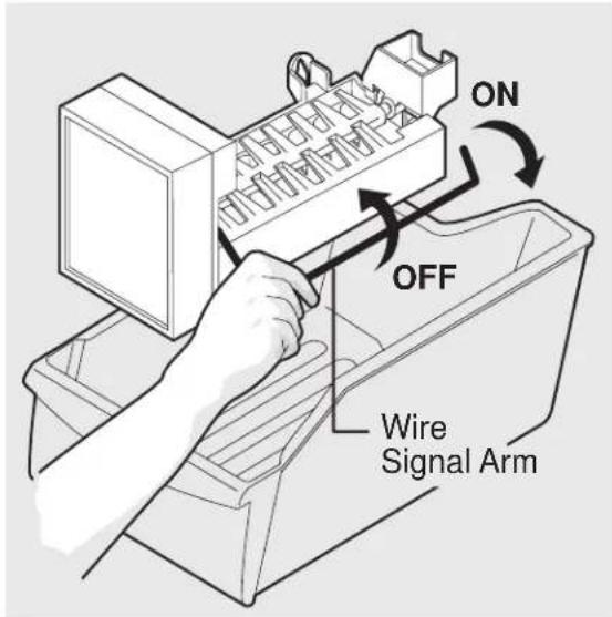
- To turn ice maker on, lower wire signal arm. (See ice maker front cover for on/off position of arm.)

CAUTION
To Avoid Property Damage:
- Copper tubing is recommended for the water supply line. Water supply tubing made of 14 inch plastic should not be used since it greatly increases the potential for water leaks. The manufacturer will not be responsible for any damage if plastic tubing is used for the supply line.
- DO NOT install water supply tubing in areas where temperatures fall below freezing.
- If the water source uses a water softener, ensure that the softener is maintained and working properly. Chemicals from a malfunctioning softener can damage the ice maker.

NOTE
A water line kit is available from your appliance dealer at additional cost. It contains 25 feet (7.6 meters) of 14 inch OD copper tubing, a saddle type shutoff valve (non-piercing), (2) 14 inch brass compression nuts, (2) ferrules/sleeves, and instructions for installing a water supply line.

IMPORTANT
It takes approximately 24 hours for the ice maker to begin producing ice. Air in new plumbing lines may cause ice maker to cycle two or three times before making a full tray of ice. New plumbing may cause ice to be discolored or have poor flavor. Discard ice made during the first 24 hours.
Automatic Ice Maker Tips
Remember that water quality determines your ice quality. If the water source uses a water softener, ensure that the softener is maintained and working properly. Chemicals from a malfunctioning softener can damage the ice maker.
To stop the ice maker, lift the wire signal arm until it clicks and locks in the "up" or OFF position. The ice maker turns off automatically when the ice container is full. If your model has an adjustable freezer shelf, place the shelf so the wire signal arm will hit the ice when the ice container is full.
Ice Maker Tips
- Ice stored too long may develop an odd flavor. Empty the container and be sure the wire signal arm is in its "down" or ON position. The ice maker will then produce more ice.
• Occasionally shake the container to keep ice separated. - Keep the wire signal arm in its "up" or OFF position until the refrigerator is connected to the water supply or whenever the water supply is turned off.
- The following sounds are normal when the ice maker is operating.
- Motor running
- Ice loosening from tray
- Ice dropping into ice container
- Running water
- Water valve opening or closing

CAUTION
Do Not place the ice container in your dishwasher.
- Wash ice container in warm water with mild detergent. Rinse well and dry.
- Stop the ice maker when cleaning the freezer or for short vacations.
- If the ice maker will be turned off for a long period of time, turn the water supply valve to the closed position.
natural_image
Line drawing of a mechanical device with internal components and mounting bracket (no text or symbols)P/N: 240394908
natural_image
Technical line drawing of a mechanical component with no visible text or symbols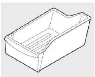
natural_image
Line drawing of a rectangular plastic container with internal compartments (no text or symbols)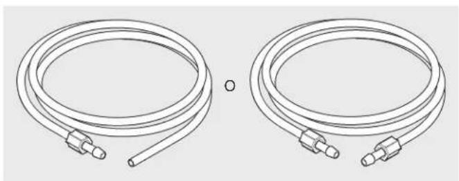
natural_image
Two identical wire hoses with connectors, shown side by side (no text or symbols)natural_image
Line drawing of a screw with a flanged head and threaded shaft (no text or symbols)
natural_image
Line drawing of a screw with hexagonal head and pointed tip (no text or symbols)
natural_image
Line drawing of a hexagonal bolt with threaded base (no text or symbols)
natural_image
Simple line drawing of a folded paper or metal bracket with two slots (no text or symbols)natural_image
Simple line drawing of a bent metal bracket with a slot (no text or symbols)natural_image
Isometric line drawing of a mechanical clamp or bracket (no text or symbols)(2 unidades)
natural_image
Technical line drawing of two identical mechanical valve assemblies with no text or symbolsnatural_image
Line drawing of a mechanical tool or rod with a flanged end and central shaft (no text or symbols)natural_image
Simple line drawing of a circular object with a central hole (no text or symbols)natural_image
Illustration of a hand holding a cylindrical device with a curved cable, showing an arrow indicating direction (no text or symbols)natural_image
Line drawing of a mechanical device with internal compartments and mounting brackets (no text or symbols)natural_image
Technical line drawing of a mechanical component with no visible text or symbols
natural_image
Line drawing of a rectangular plastic container with internal slots (no text or symbols)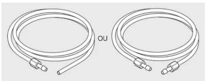
natural_image
Two identical wire hoses with connectors, labeled 'OU' in the center (no additional text or symbols)natural_image
Line drawing of a screw with a flanged head and threaded shaft (no text or symbols)
natural_image
Line drawing of a screw with hexagonal head and threaded shaft (no text or symbols)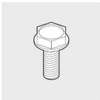
natural_image
Line drawing of a hexagonal bolt with threaded base (no text or symbols)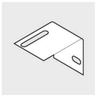
natural_image
Simple line drawing of a folded paper or metal bracket with two slots (no text or symbols)natural_image
Simple line drawing of a mechanical bracket or bracket (no text or symbols)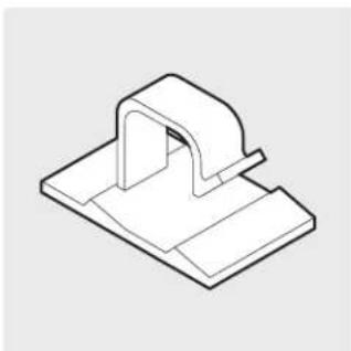
natural_image
Isometric line drawing of a mechanical clamp or bracket component (no text or symbols)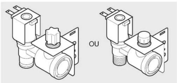
natural_image
Technical line drawing of two identical mechanical valve assemblies (no text or symbols)natural_image
Line drawing of a mechanical tool or rod with a flanged end and central shaft (no text or symbols)
natural_image
Simple line drawing of a circular object with a central hole (no text or symbols)Qté 1
natural_image
Illustration of a hand holding a cylindrical device with a curved arrow indicating motion (no text or symbols)- AUTOMATIC ICE MAKER INSTALLATION INSTRUCTIONS
- WARNING
- CAUTION
- Use This Page to Identify Parts
- ICE MAKER INSTALLATION INSTRUCTIONS
- NOTE
- Connecting Ice Maker to Water Supply
- IMPORTANT
- Before Installing The Water Supply Line, You Will Need:
- To Connect Water Supply Line To Ice Maker Inlet Valve
- Automatic Ice Maker Tips
- Ice Maker Tips
Brand : FRIGIDAIRE
Model : RNAB081J1JBRG
Category : Ice machine