755 - Measuring equipment Testo - Free user manual and instructions
Find the device manual for free 755 Testo in PDF.
| Product type | Current/voltage tester (clamp meter) |
| Model | Testo 755 (755-1 or 755-2) |
| Main functions | AC/DC voltage measurement (6-600 V for 755-1, 6-1000 V for 755-2), AC current measurement up to 200 A, continuity test (0-30 Ω), resistance test (30 Ω-100 kΩ), single-pole phase detection (755-2), phase rotation (755-2) |
| Voltage range | 6 … 600 V AC/DC (755-1); 6 … 1000 V AC/DC (755-2) |
| Current range | 0 … 200 A AC |
| Resolution | Voltage: 0.1 V; current: 0.1 A |
| Measurement category (voltage) | CAT III 1000 V / CAT IV 600 V |
| Measurement category (current) | CAT III 600 V / CAT IV 300 V |
| Protection rating | IP64 |
| Power supply | 2 AAA batteries (1.5 V, IEC LR03) |
| Battery life | More than 10,000 measurements (duration < 5 s) |
| Display | LCD with backlight, AC/DC/HOLD indicators, battery, overload |
| Dimensions (H x W x D) | 199 x 62 x 40 mm |
| Weight | 320 g |
| Operating temperature | -10 °C to +50 °C |
| Max. humidity | 75 % RH |
| Max. altitude | 2000 m |
| Safety | Complies with EN 61243-3, DIN VDE 0682-401, DIN EN 61010-1; approvals TÜV GS, CE, CSA |
| Warranty | 2 years (conditions at www.testo.com/warranty) |
| Maintenance | Clean with a damp cloth and mild detergent; do not use solvents; replace batteries when battery symbol appears |
| Repairability | Battery replacement by user; other repairs by Testo service center |
| Included accessories | Removable test probes, cables, widening caps/tips, batteries |
Frequently Asked Questions - 755 Testo
User questions about 755 Testo
0 question about this device. Answer the ones you know or ask your own.
Ask a new question about this device
Download the instructions for your Measuring equipment in PDF format for free! Find your manual 755 - Testo and take your electronic device back in hand. On this page are published all the documents necessary for the use of your device. 755 by Testo.
USER MANUAL 755 Testo
Current/voltage tester
Instruction
m
text_image
CATN HOT CATN HOT AC 999.9 V HOLD testa L1 L23 Safety instructions.... 16
4 Intended use.... 17
5 Technical data....17
6 Overview....20
6.1. Display and control elements...... 20
6.2. Explanation of icons.... 21
7 Operating the instrument....22
7.1. Switching the instrument on.... 22
7.2. Switching measuring point illumination on/off 22
7.3. Switching the instrument off.... 22
8 Carrying out a test....22
8.1. Preparing the test 22
8.2. Voltage testing 23
8.3. Single pole phase testing (only testo 755-2) .. 23
8.4. Current measurement....23
8.5. Continuity/resistance testing 23
8.6. Rotating magnetic field direction detection (only testo 755-2)....24
9 Service and maintenance.... 24
9.1. Replacing the batteries 24
9.2. Maintenance 24
9.3. Storage 25
9.4. Cleaning 25
10 Protecting the environment 26
2 Observe prior to use!
- The instruction manual contains information and instructions which are necessary for operating and using the instrument safely. Before using the instrument, read the instruction manual carefully and comply with all aspects of it. Keep this document to hand so that you can refer to it when necessary. Forward this documentation to any subsequent users of the instrument.
- If the manual is not followed, or if you fail to observe the warnings and instructions, there is a risk of fatal injury to the user and damage to the instrument.
- Before using the fork meter in places with loud background noise, make sure that the acoustic signal is discernible.
3 Safety instructions
- The instrument may only be used by trained personnel. During all operations, please observe the Employers' Liability Insurance Association provisions for health and safety at work.
- In order to prevent electric shock, take safety precautions when working with voltages greater than 120 V (60 V) DC or 50 V (25 V) rms. AC. These values are the limit for contact voltages in accordance with DIN VDE (values in brackets apply to restricted areas, for example agricultural sectors).
- The instrument may only be touched at the designated grip areas, the display elements must not be covered.
- Maintenance work that is not described in this documentation must only be carried out by trained service technicians.
- If the instrument is modified in any way, operational safety can no longer be guaranteed.
- The fork meter must not be used while its battery compartment is open.
- Batteries must be checked before use and changed if necessary.
- If there is any battery leakage, the instrument must no longer be used until it has been checked by our Customer Service.
- The battery acid (electrolyte) is highly alkaline and electrically conductive. Risk of acid burn! If the battery acid comes into contact with your skin or clothing, thoroughly rinse the areas affected immediately with plenty of water. If battery acid gets into your eyes, rinse them immediately with plenty of water and seek medical advice.
4 Intended use
The instrument may only be used under the conditions and for the purpose for which it was designed:
- Current measurement, voltage testing in the AC/DC range of 6 to 600 V (testo 755-1) or 6 to 1000 V (testo 755-2), continuity testing / resistance testing
- Only use the instrument within the specified measuring ranges of the following overvoltage categories:
- Voltage measurement: CAT IV 600V, CAT III 1000 V
- Current measurement: CAT IV 300V, CAT III 600 V
The instrument must not be used for the following circumstances:
- In potentially explosive atmospheres: the instrument is not explosion-proof!
- When there is rain or other precipitation: risk of electric shock!
5 Technical data
Voltage testing
Figures correspond to +23 °C ± 5 °C at <80% rel. humidity. Temperature coefficient: 0.15 x specified accuracy per 1 °C (<18 °C and >28 °C).
| Feature Values | |
| Voltage range testo 755-1: 6 | 600 V AC/DCTesto 755-2: 6 - 1000 V AC/DC |
| Resolution 0.1 V | |
| Tolerance 6 to 49.9 V: ± (1.5% of the display value + 5 digits)50 to 600 V / 1000 V: ± (1.5% of the display value + 3 digits) | |
| Frequency range DC voltage, | 14 Hz – 400 Hz |
| Acoustic signalling | ≥ 50 V AC, ≥ 120 V DC |
| Voltage detection Automatic | |
| Polarity detection Automatic | |
| Range detection Automatic | |
| Internal load Approx. 3.5 W at | 1000 V |
| Current Is < 3.5 mA at 1000 V | |
| Operating time 30 s | |
| Recovery time 240 s | |
| Automatic power on >6 V | |
| Reading memory (HOLD) testo 755-1: 6 - 600 V AC/DCTesto 755-2: 6 - 1000 V AC/DC | |
| Overload indicator | testo 755-1: > = 630 V AC/DC, LC display shows OLtesto 755-2: > = 1050 V AC/DC, LC display shows OL |
| Measurement category | CAT III 600 V / CAT IV 300 V |
Single pole phase testing (only testo 755-2)
| Feature Values | |
| Voltage range >90 to 690 V ± 10% AC voltage to earth | |
| Frequency range 50/60 Hz | |
| Acoustic signalling | Yes |
| LED display Warning symbol | |
Rotating magnetic field detection (only testo 755-2)
| Feature Values | |
| Voltage range 100 to 4 | 00 V ± 10% phase to earth/neutral |
| Frequency range 50/60 | Hz |
| LC display | L and R |
Current test
| Feature Values | |
| Voltage range Max. 200 A AC | |
| Frequency range 40 to 70 Hz | |
| Resolution 0.1 A ± (3% of the display value + 3 digits) | |
| Automatic power on > 10 A | |
| Overload indicator >= 220 A, LC display shows OL | |
| Measurement category CAT III 600 V / CAT IV 300 V | |
Continuity testing
| Feature Values | |
| Area 0 to 30 Ω | |
| Tolerances ± (1% of the display value + 5 digits) | |
| Test current < 5 μA | |
| Acoustic signalling Yes | |
| Overvoltage protection | 1000 V AC/DC |
| Automatic power on < 100 kΩ | |
Resistance testing
| Feature Values | |
| Area | 30 Ω to 100 kΩ |
| Tolerances ± (1% of the display value + 5 digits) | |
| Test current < 5 μA | |
| Overvoltage protection | 1000 V AC/DC |
| Automatic power on < 100 kΩ | |
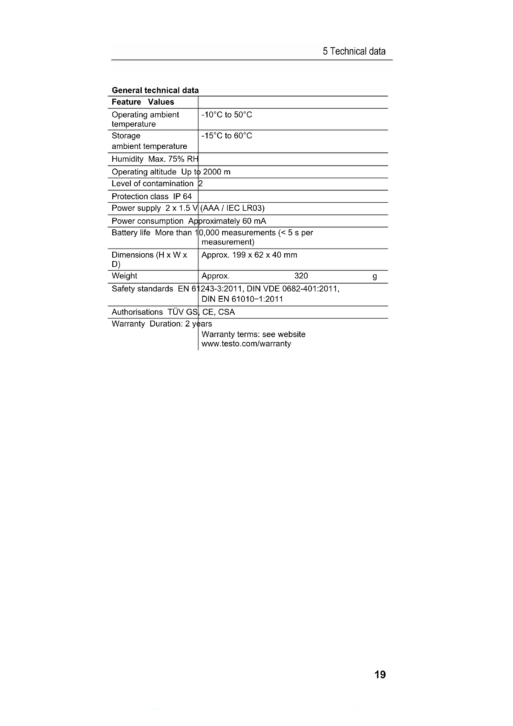
General technical data
| Feature Values | |
| Operating ambient temperature | -10°C to 50°C |
| Storage ambient temperature | -15°C to 60°C |
| Humidity Max. 75% RH | |
| Operating altitude Up to 2000 m | |
| Level of contamination | 2 |
| Protection class IP 64 | |
| Power supply 2 x 1.5 V | (AAA / IEC LR03) |
| Power consumption Approximately 60 mA | |
| Battery life More than 10,000 measurements (< 5 s per measurement) | |
| Dimensions (H x W x D) | Approx. 199 x 62 x 40 mm |
| Weight | Approx. 320 g |
| Safety standards EN 61243-3:2011, DIN VDE 0682-401:2011, DIN EN 61010-1:2011 | |
| Authorisations TÜV GS, CE, CSA | |
| Warranty Duration: 2 years Warranty terms: see website www.testo.com/warranty | |
6 Overview
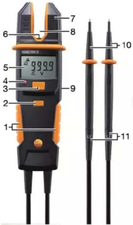
6.1. Display and control elements
text_image
Tinko 705-2 1 2 3 4 5 6 7 8 9 10 11 L1 L21 Grip area
2 Switch on measuring point illumination and LC display illumination
3 HOLD (record reading)
4 LED safety extra-low voltage exceeded
5 LC display
Display Meaning
AC AC voltage is applied
DC DC voltage is applied
HOLD Reading is recorded
V Voltage in V
A Current in A
8
- Safety extra-low voltage exceeded (> 50 V AC / > 120 V DC)
- Single pole phase testing (only testo 755-2): phase detected
Ω, kΩ
Resistance in ohms or kilo-ohms
•
Continuity
L, R
Rotating magnetic field direction left or right
Display Meaning

Battery (full / empty)
6 Measuring point illumination, white LED
7 Fork meter for conductor up to 12.9 mm (0.5") in diameter
8 Sensor zone current measurement
9 On the rear: battery compartment and bracket for the probe tips
10 Probe tips, exchangeable (plug-in connection, adhere to polarity: see printing on probe tips and sockets!)
11 Probe tip cable with sockets for probe tips
6.2. Explanation of icons
Icon Meaning
 | Attention! Warning about a danger spot, refer to instruction manual | |
 | Caution! Dangerous voltage, risk of electric shock | |
 | Continuous double or reinforced insulation in accordance with category II DIN EN 61140 | |
 | Suitable for work on live parts | |
 | Conformity mark, verifies compliance with the valid EU Directives: EMC Directive (2014/30/EU) with the EN 61326-1 standard, Low-Voltage Directive (2014/35/EU) with the EN 61010-1 standard | |
 | Fulfils applicable Australian provisions | |
 | The instrument complies with the WEEE Directive (2012/19/EU) |
7 Operating the instrument
7.1. Switching the instrument on
Connect both probe tips or press any button.
- The instrument is switched on, the LC display shows ---.
7.2. Switching measuring point illumination on/off
To switch on/off: briefly press the button.
The measuring point illumination switches off automatically after 2 minutes.
7.3. Switching the instrument off
Automatic
If there is no voltage being applied to the probe tips and no current or continuity is detected, the instrument switches off automatically after 10 seconds.
Manual
Switch off instrument manually: press [HOLD] >2 s
8 Carrying out a test
8.1. Preparing the test
Prior to every test, please ensure that the instrument is in perfect condition:
- For example, keep an eye out for broken housing or leaking batteries.
- Always carry out a function test before using the voltage tester, see below.
- Check that the instrument is functioning perfectly (for example at a known voltage source) before and after every test.
- If the safety of the user cannot be guaranteed, the instrument must be switched off and secured to prevent unintentional usage.
Carrying out a function test
Press HOLD for approx. 2 s.
- Instrument carries out a self-test. All segments of the LC display and the alarm, along with the measuring point and display illumination, are activated for approx. 2 s.
Recording a reading
A reading is displayed: press the HOLD key.
- A short acoustic signal is emitted and the LC display shows the recorded reading.
To delete the recorded value, press the HOLD button once again.
- A short acoustic signal is emitted.
The recorded value will automatically be deleted after approx. 10 seconds once voltage is no longer being applied to the probe tips. This is indicated by a short acoustic signal.
Voltages below 6 V AC/DC cannot be recorded, ---- is shown on the LC display.
Removing/installing the probe tip protector/extension
The probe tip protector and extension can be removed/installed as required. Attention: Use of the probe tip protector may be required depending on the national regulations or provisions!
Probe tip protector: push onto probe tips or pull off.
Probe tip extension: screw onto probe tips or unscrew.
8.2. Voltage testing
Connect both probe tips to the test object.
- The instrument switches on automatically at a voltage of approximately 6 V or above.
- The voltage is shown in the LC display.
- In the case of DC voltage, the polarity of the indicated voltage relates to the voltage tester probe tip.
- When the safety extra-low voltage is reached or exceeded (50 V AC / 120 V DC), an acoustic signal is emitted, the red LED comes on and is illuminated in the LC display.
8.3. Single pole phase testing (only testo 755-2)
Single pole phase testing is possible as from AC voltages of approx. 90 V.
During single pole phase testing to determine external conductors, the display function may be impaired, for example due to insulating personal protective equipment or other insulators.
Single pole phase testing is not suitable for testing for absence of voltage. Two-pole voltage testing is required for this.
Connect a probe tip of the voltage tester to the test object.
- is illuminated to signify phase testing on the relevant conductor.
8.4. Current measurement

Strong interferences in the vicinity result in an unstable display and measurement errors.
√ No voltage must be applied to the probe tips, so that the instrument switches to current measurement mode.
Push the instrument's fork over the live conductor as far as the sensor zone.
- The reading is shown in the LC display.
8.5. Continuity/resistance testing
√ Disconnect the test circuit/object from the power supply.
√ Conduct a two-pole voltage test on the test object to confirm the absence of voltage.
Connect both probe tips to the test object.
- For continuity up to approx. 30 Ω, an acoustic signal is emitted, for resistance up to approx. 100 kΩ the acoustic alarm remains inactive.
- The instrument switches off automatically after 10 seconds if no continuity/resistance is detected. As soon as continuity/resistance is detected, the instrument switches back on automatically.
8.6. Rotating magnetic field direction detection (only testo 755-2)
The rotating magnetic field direction detector is always active, L or R may be constantly illuminated, however rotary field direction can only be determined in a three-phase system between the external conductors.
The instrument displays the voltage between two external conductors.
-
Connect the probe tip L1 (-) to the presumed phase L1 and the probe tip L2 (+) to the presumed phase L2.
-
Completely cover the grip area with your hands!
- If R is constantly illuminated: "right" rotating magnetic field.
- If L is constantly illuminated: "left" rotating magnetic field.
Cross-check:
Repeat the process with switched probe tips.
- The opposite result must be indicated.
9 Service and maintenance
9.1. Replacing the batteries
The batteries must be replaced when the battery icon is illuminated in the LC display.
- Fully disconnect the instrument from the measurement object.
- Using a screwdriver, unscrew the two metal screws on the battery compartment until the battery compartment cover can be removed. Do not unscrew the screws completely.
- Remove the spent batteries.
- Insert new batteries, type AAA / IEC LR03 (1.5 V), ensuring correct polarity.
- Put the battery compartment cover back on and screw down.
9.2. Maintenance
When operated in accordance with the instruction manual, the instrument does not require any particular maintenance.
If a malfunction occurs during operation, the ongoing measurement should be stopped immediately. Send the instrument to Testo Service for checking.
9.3. Storage

Storage areas must be dry.
If the instrument is not in use for a significant period of time: remove the batteries in order to prevent any danger or damage due to any potential leaking of the batteries.
9.4. Cleaning
Prior to cleaning, the instrument must be disconnected from all measuring circuits.
Wipe the instrument with a damp cloth and a small amount of mild household detergent.
Never use any harsh cleaning agents or solvents to clean the instrument! After being cleaned, the instrument must not be used until it has completely dried.
10 Protecting the environment
Dispose of faulty rechargeable batteries/spent batteries in accordance with the valid legal specifications.
At the end of its useful life, send the product to the separate collection for electric and electronic devices (observe local regulations) or return the product to Testo for disposal.
1 Sommaire
1 Sommaire 27