S6035 - Air Conditioning QLIMA - Free user manual and instructions
Find the device manual for free S6035 QLIMA in PDF.

| Product Type | Split air conditioner (indoor unit + outdoor unit) |
| Brand | Qlima |
| Model | S6035 |
| Refrigerant | R32 (flammable, GWP=675) |
| Operating modes | Cooling, Heating, Dehumidification, Fan, Sleep, Turbo, Eco, Quiet |
| Special functions | Auto restart, Anti-mold, Wireless control (optional), Slot angle memory, Active Clean, Breeze Away, Refrigerant leak detection, UV-C lamp (depending on model) |
| Power supply | 220-240 V ~ 50 Hz (standard estimate) |
| Temperature range - Cooling mode | Indoor: 16°C to 32°C; Outdoor: 0°C to 50°C |
| Temperature range - Heating mode | Indoor: 0°C to 30°C; Outdoor: -15°C to 30°C |
| Temperature range - Dry mode | Indoor: 10°C to 32°C; Outdoor: 0°C to 50°C |
| Safety | Overload protection (3 min), refrigerant leak detection, automatic shutdown on anomaly, mandatory grounding |
| Maintenance | Clean the filter every 2 weeks; cleaning reminder after 240h, replacement reminder after 2880h |
| Warranty | 2 years parts, 4 years compressor |
| Included accessories | Manual, remote control, batteries (2× AAA), drain gasket, mounting plate, screws, small filter |
| Installation | Must be done by a certified technician; max piping length up to 25 m (depending on capacity); max height 10 m |
| Energy class | Not specified |
Frequently Asked Questions - S6035 QLIMA
User questions about S6035 QLIMA
0 question about this device. Answer the ones you know or ask your own.
Ask a new question about this device
Download the instructions for your Air Conditioning in PDF format for free! Find your manual S6035 - QLIMA and take your electronic device back in hand. On this page are published all the documents necessary for the use of your device. S6035 by QLIMA.
USER MANUAL S6035 QLIMA
natural_image
Exterior view of a Qlima air conditioner unit with circular fan blades (no text or symbols visible on the device body)guarantee
4
YEARS
| D | GEBRAUCHSANLEITUNG | 2 |
| E | MANUAL DE INSTRUCCIONES | 50 |
| F | MANUEL D'UTILISATION | 98 |
| GB | OPERATING MANUAL | 144 |
| I | MANUALE OPERATIVO | 188 |
| NL | GEBRUIKSAANWIJZING | 234 |
| P | MANUAL DE INSTRUÇÕES | 280 |
natural_image
Simple line drawing of a garage with a patterned back cover and window (no text or symbols)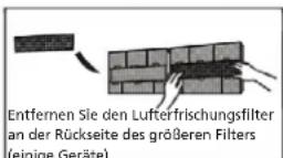
natural_image
Diagram showing a falling faucet above a textured rectangular object with a starburst pattern (no text or symbols)
VORSICHT
natural_image
Diagram of a 3x3 grid with a small arrow pointing to the top-right corner (no text or symbols)natural_image
Simple line drawing of a house-shaped structure with wavy lines inside, no text or symbols present.text_image
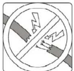
Warning symbol with crossed-out lightning bolt inside a circle, indicating no protection or resistance.natural_image
Simple line drawing of a mechanical device with no text or symbolsnatural_image
Cross-sectional diagram of a crossed-out electrical circuit with lightning bolts indicating resistance (no text or symbols)natural_image
Simple line drawing of a grid with a speaker icon, no text or symbols presentnatural_image
Simple circular diagram with a diagonal line crossing a shaded rectangle, and two droplet symbols inside (no text or labels)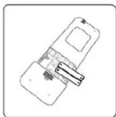
natural_image
Simple line drawing of a handheld device with a clip and handle (no text or symbols)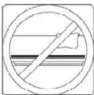
natural_image
Pure technical diagram of a mechanical component with no text, numbers, or symbolsnatural_image
Illustration of a hand using a tool to adjust a component, with a ruler and magnified view (no text or symbols)natural_image
Mechanical diagram showing a tool interacting with a bolt and pipe (no text or symbols)natural_image
Illustration of hands holding a black object over a textured surface (no text or symbols)natural_image
Diagram of a cable being inserted into a wire, showing sheath and sheath cross-section (no text or symbols)natural_image
Illustration of hands holding a rectangular object with three upward arrows indicating motion or force (no text or symbols)text_image
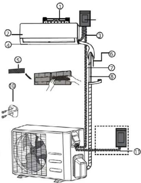
Diagram of an air conditioner system with numbered components and labeled parts for installation or maintenance.(1)
text_image
Diagram of an air conditioner system with numbered components and installation steps(2)
natural_image
Line drawing of a rectangular electronic component or enclosure with internal compartments and mounting holes (no text or symbols)text_image
5-7mm (0.2-0.275in)ABMESSUNGEN MONTAGEPLATTE
text_image
Diagram showing three mechanical assembly states with check and cross symbols indicating selection or failure.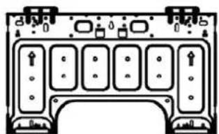
natural_image
Pure electrical circuit lines without any symbolsType A
natural_image
Pure architectural line drawing of a symmetrical structure with no text, numbers, or symbolsType B
text_image
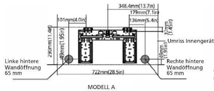
348.4mm(13.7in) 179mm(7.1in) 136mm(5.4in) 37mm (1.45in) Umriss Innengerät 290mm(11.4ft) 49mm(1.95in) 49mm(1.95in) 49mm(1.95in) Linke hintere Wandöffnung 65 mm 722mm(28.5in) Rechte hintere Wandöffnung 65 mm MODELL A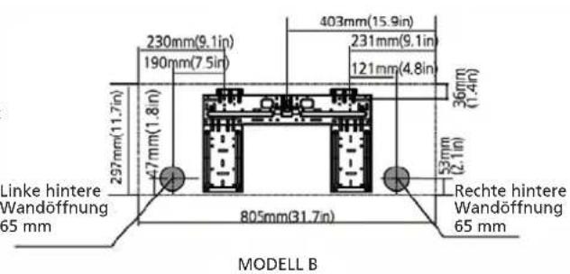
text_image
230mm(9.1in) 190mm(7.5in) 403mm(15.9in) 231mm(9.1in) 121mm(4.8in) 360mm (1.4in) 297mm(11.7in) 47mm(1.8in) 53mm (2.1in) Linke hintere Wandöffnung 65 mm 805mm(31.7in) Rechte hintere Wandöffnung 65 mm MODELL B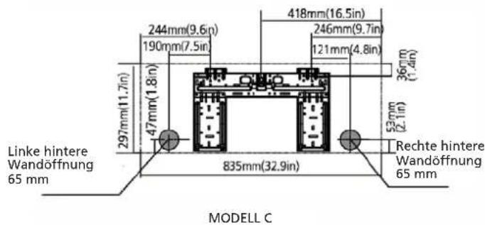
text_image
244mm(9.6in) 190mm(7.5in) 418mm(16.5in) 246mm(9.7in) 121mm(4.8in) 36mm (1.4in) 297mm(11.7in) 47mm(1.8in) 53mm (2.1in) Rechte hintere Wandöffnung 65 mm 835mm(32.9in) Linke hintere Wandöffnung 65 mm MODELL C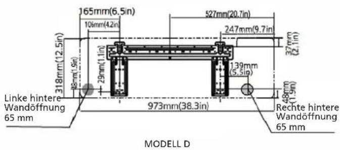
text_image
165mm(6.5in) 106mm(4.2in) 318mm(12.5in) 29mm(1.1in) 37mm(2.1in) 527mm(20.7in) 247mm(9.7in) 139mm(5.5in) 318mm(1.9in) 973mm(38.3in) Rechte hintere Wandöffnung 65 mm LINKE hintere Wandöffnung 65 mm MODELL D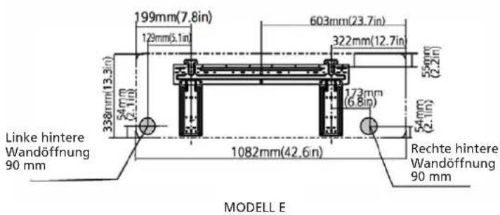
text_image
199mm(7.8in) 129mm(5.1in) 603mm(23.7in) 322mm(12.7in) 338mm(13.3in) 54mm (2.1in) 173mm (6.8in) 55mm (2.2in) 338mm(13.3in) 54mm (2.1in) 1082mm(42.6in) Rechte hintere Wandöffnung 90 mm MODELL E Linke hintere Wandöffnung 90 mm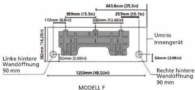
text_image
643.6mm (25.3in) 389mm (15.3in) 257mm (10.1in) 172mm (6.6in) 332mm (12.05in) Umriss Innengerät 362mm (14.25in) 52mm (2.05in) 52mm (2.05in) Linke hintere Wandöffnung 90 mm 1259mm (49.5sin) Rechte hintere Wandöffnung 90 mm MODELL Fnatural_image
Technical line drawing of two rectangular electronic components with coiled spring and mounting brackets (no text or symbols)
VORSICHT
natural_image
Simple line drawing of a bracket and vertical wall with a checkmark (no text or symbols)RICHTIG
natural_image
Simple line drawing of a mechanical joint or bracket with a hatched wall and a vertical bar, no text or symbols present.NICHT RICHTIG
natural_image
Simple line drawing of a wall joint with a bracket and a cross symbol (no text or labels)NICHT RICHTIG
natural_image
Simple line drawing of a pipe connection with a cross symbol (no text or labels)NICHT RICHTIG
natural_image
Hand holding a cylindrical object with a knife inserted, no text or symbols visibletext_image
30-50 mm 30-50 mmnatural_image
Mechanical component diagram showing a flanged housing with mounting points and a central height dimension labeled 'h' (no text or symbols beyond the label)natural_image
Technical illustration of a mechanical clamp or lever assembly (no text or symbols)natural_image
Illustration of a hand using a tool to lift a mechanical component (no text or symbols)| Außendurchmesser der Leitung (mm) | Drehmoment (Nm) Bördela | bmessung (B) (mm) | Bördelform |
| ∅ 6,35 (∅ 0,25") 18~20 8,4 | -8,7 (0,33~0,34") | 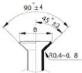 | |
| ∅ 9,52 (∅ 0,375") 32~39 13 | 2~13,5 (0,52~0,53") | ||
| ∅ 12,7 (∅ 0,5") 49~59 16,2 | -16,5 (0,64~0,65") | ||
| ∅ 16 (∅ 0,63") 57~71 19,2 | -19,7 (0,76~0,78") | ||
| ∅ 19 (∅ 0,75") 67~101 23,2 | -23,7 (0,91~0,93") |

natural_image
Line drawing of hands using a tool to adjust or install a mechanical component (no text or symbols present)natural_image
Technical line drawing of an air conditioner unit with internal panel layout (no text or symbols)Manual control-Taste
M GARANTIEBEDINGUNGEN
natural_image
Simple line drawing of a hand opening a car with a checkered pattern on the windshield (no text or symbols)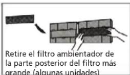

PRECAUCIÓN
natural_image
Diagram of a grid with a label 'H' pointing to the top-right corner (no text or symbols on the grid itself)natural_image
Simple line drawing of a house with wavy lines inside, no text or symbols presenttext_image
Warning symbol with crossed-out lightning bolt inside a circlenatural_image
Simple line drawing of a smartphone with a partially open screen and cable (no text or symbols)text_image
Safety warning sign showing a crossed-out electrical circuit with lightning bolts indicating hazard or leakagenatural_image
Simple line drawing of a grid with a triangular pointer labeled 'M' (no text or symbols beyond the label)natural_image
Simple diagram showing a diagonal line crossing a shaded rectangle with two droplet symbols inside (no text or labels)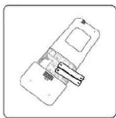
natural_image
Simple line drawing of a smartphone with a strap and display panel (no text or symbols)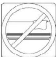
natural_image
Pure technical diagram of a mechanical component with no text, numbers, or symbolsnatural_image
Technical diagram of a mechanical device with adjustment knobs and a ruler, no visible text or symbolsnatural_image
Diagram showing a pipe clamp securing a bolt, with motion arrows indicating movement (no text or symbols)natural_image
Illustration of hands holding a small object with a textured surface, no text or symbols presentnatural_image
Diagram of a cable being inserted into a wire, showing sheath and sheath cross-section (no text or symbols)natural_image
Illustration of hands holding a rectangular object with three upward arrows indicating motion or force (no text or symbols)text_image
Diagram of an air conditioner system with numbered components and labeled parts for installation or maintenance.(1)
text_image
Diagram of an air conditioner system with numbered components and installation steps(2)
natural_image
Technical line drawing of a rectangular electronic device with internal compartments (no text or symbols)text_image
5-7mm (0.2-0.275in)DIMENSIONES DE LA PLACA DE MONTAJE
natural_image
Technical line drawing of two rectangular electronic components with coiled leads and connectors (no text or symbols)
PRECAUCIÓN
natural_image
Simple line drawing of a mechanical joint or bracket with a checkmark (no text or symbols)CORRECTO
natural_image
Simple line drawing of a mechanical joint or bracket with a hatched fill and a labeled X (no text or symbols beyond the label)INCORRECTO
natural_image
Simple line drawing of a pipe connection with a wall and ground, no text or symbols presentINCORRECTO
natural_image
Simple line drawing of a toilet or shower system with no text or symbolsINCORRECTO:
natural_image
Line drawing of a hand holding a cylindrical object with a pointed tip, mounted on a mechanical bracket (no text or symbols)
ANTES DE REALIZAR TRABAJOS ELÉCTRICOS, LEA ESTAS NORMAS
Make sure that the drain hose is at the bottom of the bundle. Putting the drain hose at the top of the bundle can cause the drain pan to overflow, which can lead to fire or water damage.
natural_image
Mechanical component labeled 'Hebilla' showing a bracket and mounting base (no other text or symbols visible)natural_image
3D mechanical component diagram with no visible text or symbolsnatural_image
Illustration of a hand gripping a tool over two plates (no text or symbols)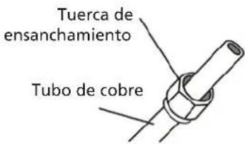
text_image
Tuerca de ensanchamiento Tubo de cobretext_image
Radio 10 cm (4in)natural_image
Illustration of a hand using a tool to lift a mechanical component (no text or symbols)natural_image
Line drawing of hands using a tool to adjust or install a mechanical component (no text or symbols present)
natural_image
Technical line drawing of an air conditioner unit showing internal panel layout (no text or labels)D. MANUEL D'INSTALLATION
E. ACCESSOIRES
F. RÉSUMÉ DE L'INSTALLATION - UNITÉ INTÉRIEURE
G. PIÈCES DE L'UNITÉ
H. INSTALLATION DE L'UNITÉ INTÉRIEURE SÉLECTIONNER L'EMPLACEMENT D'INSTALLATION FIXER LA PLAQUE DE FIXATION AU MUR PERCER UN TROU DANS LE MUR POUR LA TUYAUTERIE CONNECTIVE PRÉPARER LA TUYAUTERIE FRIGORIFIQUE RACCORDER LE TUYAU DE VIDANGE BRANCHER LE CÂBLE DE SIGNAL ENVELOPPER LA TUYAUTERIE ET LES CÂBLES MONTER L'UNITÉ INTÉRIEURE
I. INSTALLATION DE L'UNITÉ EXTÉRIEURE SÉLECTIONNER L'EMPLACEMENT D'INSTALLATION INSTALLER LE JOINT DE VIDANGE FIXER L'UNITÉ EXTÉRIEURE RACCORDER LES CÂBLES DE SIGNAL ET D'ALIMENTATION
J. RACCORDEMENT DE LA TUYAUTERIE FRIGORIFIQUE
K. VÉRIFICATIONS DES FUITES DE GAZ ET D'ÉLECTRICITÉ
L. ESSAI
M CONDITIONS DE GARANTIE
NOTE IMPORTANTE :
natural_image
Simple line drawing of a car interior with a checkered pattern on the roof (no text or symbols)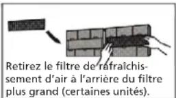

natural_image
Diagram showing a faucet above a grid-patterned object with a starburst effect (no text or symbols)
ATTENTION
natural_image
3D grid diagram with a small arrow labeled 'u' pointing upward (no text or symbols on the grid itself)natural_image
Simple line drawing of a house with wavy lines inside, no text or symbols presenttext_image
Warning symbol with crossed-out lightning bolt inside a circle, indicating no protection or hazard.natural_image
Simple line drawing of a device with a handle and internal components (no text or symbols)natural_image
Crosshair symbol of a hazard zone with lightning bolts indicating electrical hazard (no text or labels)natural_image
Diagram of a grid structure with shaded cells and an arrow labeled 'H' pointing to the top-right corner (no text or symbols beyond the label)natural_image
Simple diagram showing a diagonal line crossing a shaded rectangle with two droplet symbols inside (no text or labels)
natural_image
Simple line drawing of a handheld device with a clip and connector (no text or symbols)Remplacez les piles.
natural_image
Pure technical diagram of a mechanical component with no text, numbers, or symbolsnatural_image
Technical diagram of a mechanical assembly with no visible text or symbols- Fixer la plaque de fixation
natural_image
Illustration of a hand using a tool to adjust a component, with no visible text or symbols.natural_image
Diagram showing a tool interacting with a pipe fitting, no text or symbols present- Raccorder le câblage
natural_image
Pure electrical circuit lines without any symbolsnatural_image
Illustration of hands holding a black object over a striped cable (no text or symbols)natural_image
Diagram of a cable or cable connector with layered structure and labeled section 8 (no text or symbols on the diagram itself)natural_image
Illustration of two hands holding a rectangular object with horizontal lines and arrows indicating motion or force (no text or symbols)text_image
Diagram of an air conditioner system with numbered components and labeled parts for installation or maintenance.(1)
text_image
Diagram of an air conditioner system with numbered components and installation steps(2)
natural_image
Line drawing of a rectangular electronic component or enclosure with internal compartments (no text or symbols)text_image
Diagram showing three mechanical assembly states with check and cross symbols indicating selection or failure.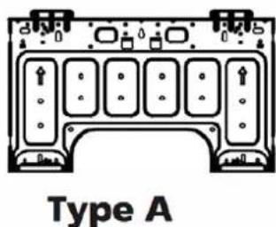
text_image
Type A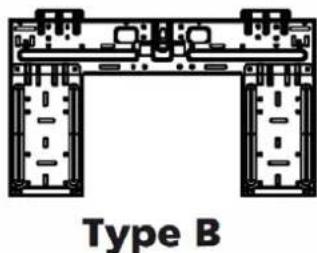
natural_image
Technical line drawing of a mechanical assembly labeled Type B, showing symmetrical components without any text or symbols.natural_image
Technical line drawing of two rectangular electronic devices with internal components and coiled leads (no text or symbols)
ATTENTION
natural_image
Pure mechanical diagram showing a bracket and checkmark symbol without any text or labelsCORRECT
natural_image
Simple line drawing of a mechanical joint or bracket with a cross symbol (no text or labels)INCORRECT
natural_image
Simple line drawing of a wall-mounted device with a bulb and base, no text or symbols presentINCORRECT
natural_image
Simple line drawing of a toilet or shower system with no text or symbolsINCORRECT
natural_image
Hand holding a cylindrical object with a pointed tip, partially installed or mounted on a metal frame (no text or symbols visible)
AVANT D' EFFECTUER DES TRAVAUX ÉLECTRIQUES, LIRE LE PRÉSENT RÈGLEMENT.
natural_image
Pure technical diagram of a mechanical component with no visible text, numbers, or symbolstext_image
30-50mm (1.18-1.96in) 30-50mm (1.18-1.96in)natural_image
Technical line drawing of a front-end air conditioner unit with fan and dimensional annotations (no text labels or symbols)| Dimensions de l’unité extérieure (mm) LxHxD | Dimensions de montage Distance A (mm) | Dimensions de montage Distance B (mm) |
| 681x434x285 (26.8"x17.1"x11.2") 460 (18.1') 292 (11.5") | ||
| 700x550x270 (27.5"x21.6"x10.6") 450 (17.7") 260 (10.2") | ||
| 700x550x275 (27.5"x21.6"x10.8") 450 (17.7') 260 (10.2") | ||
| 720x495x270 (28.3"x19.5"x10.6") 452 (17.8") 255 (10.0") | ||
| 728x555x300 (28.7"x21.8"x11.8") 452 (17.8") 302(11.9") | ||
| 765x555x303 (30.1"x21.8"x11.9") 452 (17.8') 286(11.3") | ||
| 770x555x300 (30.3"x21.8"x11.8") 487 (19.2') 298 (11.7") | ||
| 805x554x330 (31.7"x21.8"x12.9") 511 (20.1") 317 (12.5") | ||
| 800x554x333 (31.5"x21.8"x13.1") 514 (20.2') 340 (13.4") | ||
| 845x702x363 (33.3"x27.6"x14.3") 540 (21.3") 350 (13.8") | ||
| 890x673x342 (35.0"x26.5"x13.5") 663 (26.1') 354 (13.9") | ||
| 946x81 0x420 (37.2"x31.9"x16.5") 673 (26.5') 403 (15.9") | ||
| 946x810x410 (37.2"x31.9"x16.1") 673 (26.5") 403 (15.9") |
natural_image
Mechanical component with labeled Boucle component (no other text or symbols)natural_image
3D mechanical component diagram with no visible text or symbolsnatural_image
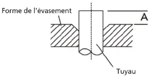
Technical line drawing of a mechanical clamp or clamping device (no text or symbols)PROLONGEMENT DE LA TUYAUTERIE AU-DELÀ DE LA TORCHÈRE
| Diamètre extérieur du tuyau (mm) | A (mm) | |
| Min. Max. | ||
| ∅ 6.35 (∅ 0.25") 0.7 (0.0275") 1.3 (0.05") | ||
| ∅ 9.52 (∅ 0.375") 1.0 (0.04") 1.6 (0.063") | ||
| ∅12.7 (∅ 0.5") 1.0 (0.04") 1.8 (0.07") | ||
| ∅ 16 (∅ 0.63") 2.0 (0.078") 2.2 (0.086") | ||
| ∅ 19 (∅ 0.75") 2.0 (0.078") 2.4 (0.094") | ||
text_image
Rayon 10cm (4in)natural_image
Illustration of hands using a tool to lift a mechanical component (no text or symbols)EXIGENCES DE COUPLE
| Diamètre extérieur du tuyau (mm) | Couple de serrage (n•m) D | mension de la torche (B) (mm) | Forme de la torche |
| ∅ 6.35 (∅ 0.25") 18~20(180 | ~200kgf.cm) 8.4~8.7 (0.33~0.34") | 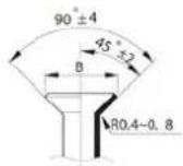 | |
| ∅ 9.52 (∅ 0.375") 32~39(32 | 0~390kgf.cm) 13.2~13.5 (0.52~0.53") | ||
| ∅ 12.7 (∅ 0.5") 49~59(490~ | 590kgf.cm) 16.2~16.5 (0.64~0.65") | ||
| ∅ 16 (∅ 0.63") 57~71(570~ | 710kgf.cm) 19.2~19.7 (0.76~0.78") | ||
| ∅ 19 (∅ 0.75") 67~101(670~ | 1010kgf.cm) 23.2~23.7 (0.91~0.93") |

NE PAS UTILISER DE COUPLE EXCESSIF
natural_image
Line drawing of a small air conditioner unit with fan and vent slots (no text or symbols)Cache-soupape
natural_image
Line drawing of hands using a manual tool to adjust or install a mechanical component (no text or symbols present)natural_image
Technical line drawing of a front air conditioner unit with ventilation grilles and ventilation slots (no text or labels)M CONDITIONS DE GARANTIE
Congratulations on the purchase of your Qlima Air Conditioner. You have acquired a high quality product that, if used responsibly, will give you many years of pleasure.
Please read these instructions for use first in order to ensure the maximum life span of your appliance.
On behalf of the manufacturer, we provide a 24-month guarantee on all material and production defects and a 48-month guarantee on the compressor of the appliance.
Please enjoy your appliance.
Yours sincerely,
PVG Holding b.v.
Customer service department
-
READ THE DIRECTIONS FOR USE FIRST.
-
IN CASE OF ANY DOUBT, CONTACT YOUR DEALER.
TABLE OF CONTENTS
A
SAFETY PRECAUTIONS
B. UNIT SPECIFICATIONS AND FEATURES INDOOR UNIT DISPLAY OPERATING TEMPERATURE SPECIAL FEATURES SETTING ANGLE OF AIRFLOW MANUAL OPERATION(WITHOUT REMOTE)
C. CARE AND MAINTENANCE
D. TROUBLESHOOTING
E. ACCESSORIES
NOTE!
Installation, maintenance and reparation of this unit must be carried out by certified technician
F. INSTALLATION SUMMARY - INDOOR UNIT
G. UNIT PARTS
H. INDOOR UNIT INSTALLATION SELECT INSTALLATION LOCATION ATTACH MOUNTING PLATE TO WALL DRILL WALL HOLE FOR CONNECTIVE PIPING PREPARE REFRIGERANT PIPING CONNECT DRAIN HOSE CONNECT SIGNAL CABLE WRAP PIPING AND CABLES MOUNT INDOOR UNIT
I. OUTDOOR UNIT INSTALLATION SELECT INSTALLATION LOCATION INSTALL DRAIN JOINT ANCHOR OUTDOOR UNIT CONNECT SIGNAL AND POWER CABLES
J. REFRIGERANT PIPING CONNECTION
K. ELECTRICAL AND GAS LEAK CHECKS
L. TEST RUN
M GUARANTEE CONDITIONS
IMPORTANT NOTE:
Read this manual carefully before installing or operating your new air conditioning unit. Make sure to save this manual for future reference.
A SAFETY INSTRUCTIONS
Read Safety Precautions Before Operation and Installation Incorrect installation due to ignoring instructions can cause serious damage or injury. The seriousness of potential damage or injuries is classified as either a WARNING or CAUTION.

WARNING
This symbol indicates the possibility of personnel injury or loss of life.

CAUTION
This symbol indicates the possibility of property damage or serious consequences.
WARNING
This appliance can be used by children aged from 8 years and above and persons with reduced physical, sensory or mental capabilities or lack of experience and knowledge if they have been given supervision or instruction concerning use of the appliance in a safe way and understand the hazards involved. Children shall not play with the appliance. Cleaning and user maintenance shall not be made by children without supervision (European Union countries).
This appliance is not intended for use by persons(including children) with reduced physical, sensory or mental capabilities, or lack of experience and knowledge, unless they have been given supervision or instruction concerning use of the appliance by a person responsible for their safety. Children should be supervised to ensure that they do not play with the appliance.
WARNINGS FOR PRODUCT USE
- If an abnormal situation arises (like a burning smell), immediately turn off the unit and disconnect the power. Call your dealer for instructions to avoid electric shock, fire or injury.
- Do not insert fingers, rods or other objects into the air inlet or outlet. This may cause injury, since the fan may be rotating at high speeds.
- Do not use flammable sprays such as hair spray, lacquer or paint near the unit. This may cause fire or combustion.
- Do not operate the appliance in places near or around combustible gases. Emitted gas may collect around the unit and cause explosion.
- Do not operate your appliance in a wet room such as a bathroom or laundry room. Too much exposure to water can cause electrical components to short circuit.
- Do not expose your body directly to cool air for a prolonged period of time.
- Do not allow children to play with the appliance. Children must be supervised around the unit at all times.
- If the appliance is used together with burners or other heating devices, thoroughly ventilate the room to avoid oxygen deficiency.
- In certain functional environments, such as kitchens, server rooms, etc., the use of specially designed air-conditioning units is highly recommended.
CLEANING AND MAINTENANCE WARNINGS
- Turn off the device and disconnect the power before cleaning. Failure to do so can cause electrical shock.
- Do not clean the appliance with excessive amounts of water.
- Do not clean the appliance with combustible cleaning agents. Combustible cleaning agents can cause fire or deformation.
CAUTION
- Turn off the appliance and disconnect the power if you are not going to use it for a long time.
- Turn off and unplug the unit during storms.
- Make sure that water condensation can drain unhindered from the unit.
- Do not operate the appliance with wet hands. This may cause electric shock.
- Do not use device for any other purpose than its intended use.
- Do not climb onto or place objects on top of the outdoor unit.
- Do not allow the appliance to operate for long periods of time with doors or windows open, or if the humidity is very high.
ELECTRICAL WARNINGS
- Only use the specified power cord. If the power cord is damaged, it must be replaced by the manufacturer, its service agent or similarly qualified persons in order to avoid a hazard.
- Keep power plug clean. Remove any dust or grime that accumulates on or around the plug. Dirty plugs can cause fire or electric shock.
- Do not pull power cord to unplug unit. Hold the plug firmly and pull it from the outlet. Pulling directly on the cord can damage it, which can lead to fire or electric shock.
- Do not modify the length of the power supply cord or use an extension cord to power the unit.
- Do not share the electrical outlet with other appliances. Improper or insufficient power supply can cause fire or electrical shock.
- The product must be properly grounded at the time of installation, or electrical shock may occur.
- For all electrical work, follow all local and national wiring standards, regulations, and the Installation Manual.
Connect cables tightly, and damp them securely to prevent external farces from damaging the terminal. Improper electrical connections can overheat and cause fire, and may also cause shock. All electrical connections must be made according to the Electrical Connection Diagram located on the panels of the indoor and outdoor units.
- All wiring must be properly arranged to ensure that the control board cover can close properly. If the control board cover is not closed properly, it can lead to corrosion and cause the connection points on the terminal to heat up, catch fire, or cause electrical shock.
- If connecting power to fixed wiring, an all-pole disconnection device which has at least 3mm clearances in all poles, and have a leakage current that may exceed 10mA, the residual current device(RCD) having a rated residual operating current not exceeding 30mA, and disconnection must be incorporated in the fixed wiring in accordance with the wiring rules.
TAKE NOTE OF FUSE SPECIFICATIONS
The appliance's circuit board (PCB) is designed with a fuse to provide overcurrent protection. The specifications of the fuse are printed on the circuit board, such as
T3.15Al/250VAC, T5Al/250VAC, T3.15A/250VAC, T5A/250VAC, T20A/250VAC, T30A/250VAC, etc.
NOTE: For the units using R32 or R290 refrigerant, only the blast-proof ceramic fuse can be used.
UV-C lamp(Applicable to the unit contains an UV-C lamp only)
This appliance contains a UV-C lamp. Please read the following instructions before opening the appliance.
- Do not operate UV-C lamps outside of the appliance.
-
Appliances that are obviously damaged must not be operated.
-
Unintended use of the appliance or damage to the housing may result in the escape of dangerous UV-C radiation. UV-C radiation may, even in small doses, cause harm to the eyes and skin.
- Before opening doors and access panels bearing the ULTRAVIOLET RADIATION hazard symbol for the conducting USER MAINTENANCE, it is recommended to disconnect the power.
- The UV-C lamp can not be cleaned, repaired and replaced.
- UV-C BARRIERS bearing the ULTRAVIOLET RADIATION hazard symbol should not be removed.

WARNING
This appliance contains an UV emitter. Do not stare at the light source.
WARNINGS FOR PRODUCT INSTALLATION
- Installation must be performed by an authorized dealer or specialist. Defective installation can cause water leakage, electrical shock, or fire.
- Installation must be performed according to the installation instructions. Improper installation can cause water leakage, electrical shock, or fire. (In North America, installation must be performed in accordance with the requirement of NEC and CEC by authorized personnel only.)
- Contact an authorized service technician for repair or maintenance of this unit. This appliance shall be installed in accordance with national wiring regulations.
- Only use the included accessories, parts, and specified parts for installation. Using non-standard parts can cause water leakage, electrical shock, fire, and can cause the unit to fail.
-
Install the unit in a firm location that can support the unit's weight. If the chosen location cannot support the unit's weight, or the installation is not done properly, the unit may drop and cause serious injury and damage.
-
Install drainage piping according to the instructions in this manual. Improper drainage may cause water damage to your home and property.
- For units that have an auxiliary electric heater, do not install the unit within 1 meter (3 feet) of any combustible materials.
8 Do not install the unit in a location that may be exposed to combustible gas leaks. If combustible gas accumulates around the unit, it may cause fire. - Do not turn on the power until all work has been completed.
- When moving or relocating the appliance, consult experienced service technicians for disconnection and reinstallation of the unit.
- How to install the appliance to its support, please read the information for details in “indoor unit installation” and “outdoor unit installation” sections.
Note about Fluorinated Gasses(Not applicable to the unit using R290 Refrigerant)
-
This air-conditioning unit contains fluorinated greenhouse gasses. For specific information on the type of gas and the amount, please refer to the relevant label on the unit itself or the "Owner's Manual - Product Fiche" in the packaging of the outdoor unit. (European Union products only).
-
Installation, service, maintenance and repair of this unit must be performed by a certified technician.
-
Product uninstallation and recycling must be performed by a certified technician.
-
For equipment that contains fluorinated greenhouse gases in quantities of 5 tonnes of CO2 equivalent or more, but of less than 50 tonnes of CO2 equivalent, if the system has a leak detection system installed, it must be checked for leaks at least every 24 months.
-
When the unit is checked for leaks, proper record-keeping of all checks is strongly recommended.
WARNING for Using R32/R290 Refrigerant
- When flammable refrigerant are employed, appliance shall be stored in a well -ventilated area where the room size corresponds to the room area as specified for operation for R32 frigerant models: Appliance shall be installed, operated and stored in a room with a floor area larger than 4m2. For R290 refrigerant models, appliance shall be installed, operated and stored in a room with a floor area larger than:
<=9000Btu/h units: 13m2
9000Btu/h and <=12000Btu/h units: 17m2
12000Btu/h and <=18000Btu/h units: 26m2
18000Btu/h and <=24000Btu/h units: 35m2
- Reusable mechanical connectors and flared joints are not allowed indoors. (EN Standard Requirements).
- Mechanical connectors used indoors shall have a rate of not more than 3g/year at 25% of the maximum allowable pressure. When mechanical connectors are reused indoors, sealing parts shall be renewed. When flared joints are reused indoors, the flare part shall be re-fabricated. (UL Standard Requirements)
- When mechanical connectors are reused indoors, sealing parts shall be renewed. When flared joints are reused indoors, the flare part shall be re-fabricated. (IEC Standard Requirements)
- Mechanical connectors used indoors shall comply with ISO 14903.
| Explanation of symbols displayed on the unit(For the unit adopts R32/R290 Refrigerant only): | |
 | WARNING:This symbol shows that this appliance used a flammable refrigerant. If the refrigerant is leaked and exposed to an external ignition source, there is a risk of fire. |
 | CAUTION:This symbol shows that the user manual should be read carefully. |
 | CAUTION:This symbol shows that the installation manual should be read carefully. |
 | CAUTION:This symbol shows that the technical manual should be read carefully. |
European Disposal Guidelines
This marking shown on the product or its literature, indicates that waste electrical and electrical equipment should not be mixed with genera/ household waste.
Correct Disposal of This Product
(Waste Electrical & Electronic Equipment)
This appliance contains refrigerant and other potentially hazardous materials. When disposing of this appliance, the law requires special collection and treatment. Do not dispose of this product as household waste or unsorted municipal waste.
When disposing of this appliance, you have the following options:
- Dispose of the appliance at designated municipal electronic waste collection facility.
- When buying a new appliance, the retailer will take back the old appliance free of charge.
- The manufacturer will take back the old appliance free of charge.
- Sell the appliance to certified scrap metal dealers.
NOTE
Disposing of this appliance in the forest or other natural surroundings endangers your health and is bad for the environment. Hazardous substances may leak into the ground water and enter the food chain.
B UNIT SPECIFICATIONS AND FEATURES
Indoor unit display
NOTE: Different models have different front panels and display windows. Not all the display codes describing below are available for the appliance you purchased. Please check the indoor display window of the unit you purchased.
Illustrations in this manual are for explanatory purposes. The actual shape of your indoor unit may be slightly different. The actual shape shall prevail.
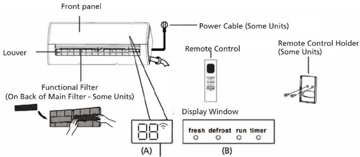
text_image
Front panel Louver Power Cable (Some Units) Functional Filter (On Back of Main Filter - Some Units) Remote Control Remote Control Holder (Some Units) Display Window (A) (B)"fresh " when Fresh and UV-C lamp(if any) feature is activated(some units)
"defrost" when defrost feature is activated.
"run" when the unit is on.
"timer" when TIMER is set.
" " when Wireless Control feature is activated(some units)
"88" Displays temperature, operation feature and error codes:
for 3 seconds when:
• TIMER ON is set (if the unit is OFF, remains on when TIMER ON is set)
- FRESH, UV-C lamp, SWING, TURBO, ECO, or SILENCE feature is turned on
for 3 seconds when:
- TIMER OFF is set
- FRESH, UV-C lamp, SWING, TURBO, ECO, or SILENCE feature is turned off
when defesting
when 8*Feating feature is turned on(some units)
when Active Clean feature is turned on(For Inverter split type)
when unit is self-cleaning(For Fixed-speed type)
Operating temperature
When your appliance is used outside of the following temperature ranges, certain safety protection features may activate and cause the unit to disable.
Inverter split type
| COOL mode HEAT mode DRY | mode | ||
| Room temperature 16°C - 32°C(60°F - 90°F) | 0°C - 30°C(32°F - 86°F) | 10°C - 32°C(50°F - 90°F) | |
| Outdoor Temperature | 0°C - 50°C(32°F - 122°F) | -15°C - 30°C(5°F - 86°F) | 0°C - 50°C(32°F - 122°F) |
| -15°C - 50°C(5°F - 122°F)(For models with low temp. cooling systems.) | |||
| 0°C - 52°C(32°F - 126°F)(For special tropical models) | 0°C - 52°C(32°F - 126°F)(For special tropical models) | ||
FOR OUTDOOR UNITS WITH AUXI LIARY ELECTRIC HEATER
When outside temperature is below 0^ (32 ° F), we strongly recommend keeping the unit plugged in at all time to ensure smooth ongoing performance.
Fixed-speed Type
| COOL mode HEAT mode DRY | mode | ||
| Room temperature 16°C - 32°C(60°F - 90°F) | 0°C - 30°C(32°F - 86°F) | 10°C - 32°C(50°F - 90°F) | |
| Outdoor Temperature | 18°C - 43°C(64°F - 109°F) | -7°C - 24°C(19°F - 75°F) | 11°C - 43°C(52°F - 109°F) |
| -7°C - 43°C(19°F - 109°F)(For models with low temp. cooling systems.) | |||
| 18°C - 52°C(64°F - 126°F)(For special tropical models) | 18°C - 52°C(64°F - 126°F)(For special tropical models) | ||
NOTE: Room relative humidity less than 80%. If the appliance operates in excess of this figure, the surface of the appliance may attract condensation. Please sets the vertical air flow louver to its maximum angle (vertically to the floor), and set HIGH fan mode.
To further optimize the performance of your unit, do the following:
- Keep doors and windows closed.
- Limit energy usage by using TIMER ON and TIMER OFF functions.
- Do not block air inlets or outlets.
• Regularly inspect and clean air filters.
A guide on using the infrared remote is not included in this literature package. Not all the functions are available for the appliance, please check the indoor display and remote control of the unit you purchased.
Other features
• Auto-Restart(some units)
If the unit loses power, it will automatically restart with the prior settings once power has been restored.
• Anti-mildew (some units)
When turning off the unit from COOL, AUTO (COOL), or DRY modes, the appliance will continue operate at very low power to dry up condensed water and prevent mildew growth.
• Wireless Control (some units)
Wireless control allows you to control your appliance using your mobile phone and a wireless connection. For the USB device access, replacement, maintenance operations must be carried out by professional staff.
- Louver Angle Memory(some units)
When turning on your unit, the louver will automatically resume its farmer angle.
• Active Clean function(some units)
-- The Active Clean Technology washes away dust when it adheres to the heat exchanger by automatically freezing and then rapidly thawing the frost. A "pi-pi" sound will be heard.
The Active clean operation is used to produce more condensed water to improve the cleaning effect, and the cold air will blow out. After cleaning, the internal wind wheel then keeps operating with hot air to blow-dry the evaporator, this keeping the inside clean.
-- When this function is turned on, the indoor unit display window appears "CL", after 20 to 130 minutes, the unit will turn off automatically and cancel Active Clean function.
-- For some units, the system will start hightemperature cleaning process, and the temperature of air outlet is very high. Please keep away from it. And this would lead to the rising of the room temperature.
- Breeze Away (some units)
This feature avoids direct air flow blowing on the body and make you feel indulging in silky coolness.
• Refrigerant Leakage Detection (some units)
The indoor unit will automatically display "ELOC" or flash LEDs (model dependent) when it detects refrigerant leakage.
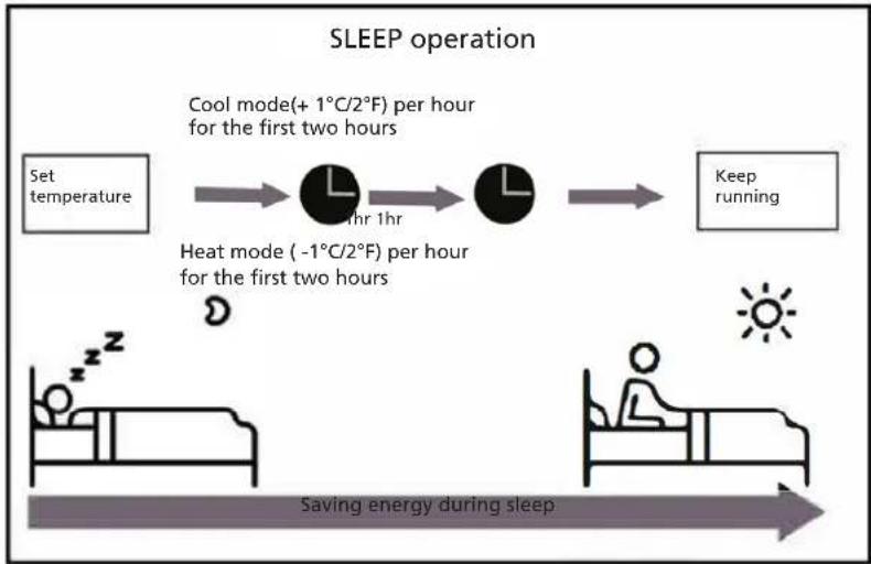
- Sleep Operation
The SLEEP function is used to decrease energy use while you sleep (and don't need the same temperature settings to stay comfortable). This function can only be activated via remote control. And the Sleep function is not available in FAN or DRY mode.
Press the SLEEP button when you are ready to go to sleep. When in COOL mode, the unit will increase the temperature by 1 °C (2° F) after 1 hour, and will increase an additional 1 °C (2° F) after another hour. When in HEAT mode, the unit will decrease the temperature by 1 °C (2° F) after 1 hour, and will decrease an additional 1 °C (2° F) after another hour.
The sleep feature will stop after 8 hours and the system will keep running with final situation.
flowchart
graph LR
    A["Set temperature"] --> B["Cool mode(+ 1°C/2°F) per hour for the first two hours"]
    B --> C["Heat mode (-1°C/2°F) per hour for the first two hours"]
    C --> D["Keep running"]
    E["Saving energy during sleep"] --> F["Sun"]
    G["Sun"] --> H["Bed with sleeping person"]
    I["Bed with sleeping person"] --> J["Bed with sleeping person"]
NOTE: For multi-split air conditioners, the following functions are not available: Active clean function, Silence feature, Breeze away function, Refrigerant leakage detection function and Eco feature.
Setting Angle of Air Flow
Setting vertical angle of air flow
While the unit is on, use the SWING/DIRECT button on remote control to set the direction (vertical angle) of airflow. Please refer to the Remote Control Manual for details.
NOTE ON LOUVER ANGLES
When using COOL or DRY mode, do not set louver at too vertical an angle for long periods of time. This can cause water to condense on the louver blade, which will drop on your floor or furnishings.
When using COOL or HEAT mode, setting the louver at too vertical an angle can reduce the performance of the unit due to restricted air flow.
NOTE: According to the relative standards requirement, please sets the vertical air flow louver to its maximum angle under heating capacity test.
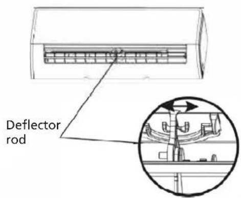
Setting horizontal angle of air flow
The horizontal angle of the airflow must be set manually. Grip the deflector rod (See Fig.B)
and manually adjust it to your preferred direction. For some units, the horizontal angle of the airflow can be set by remote control. please refer to the Remote Control Manual.
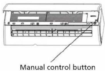
Manual Operation(without remote)

CAUTION
The manual button is intended for testing purposes and emergency operation only. Please do not use this function unless the remote control is lost and it is absolutely necessary. To restore regular operation, use the remote control to activate the unit. Unit must be turned off before manual operation.
To operate your unit manually:
- Open the front panel of the indoor unit.
- Locate the MANUAL CONTROL button on the right-hand side of the unit.
- Press the MANUAL CONTROL button one time to activate FORCED AUTO mode.
- Press the MANUAL CONTROL button again to activate FORCED COOLING mode.
- Press the MANUAL CONTROL button a third time to turn the unit off.
- Close the front panel.
text_image
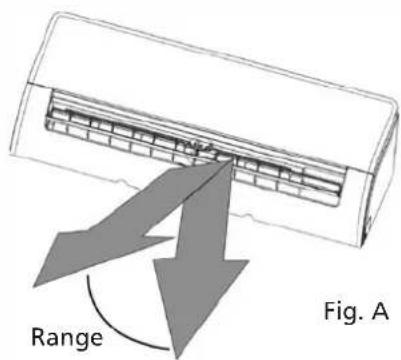
Range Fig. ANOTE: Do not move louver by hand. This will cause the louver to become out of sync. If this occurs, turn off the unit and unplug it for a few seconds, then restart the unit. This will reset the louver.

CAUTION
Do not put your fingers in or near the blower and suction side of the unit. The high-speed fan inside the unit may cause injury.
text_image
Deflector rodFig. B
text_image
Manual control buttonC CARE AND MAINTENANCE
Cleaning Your Indoor Unit

BEFORE CLEANING OR MAINTENANCE
ALWAYS TURN OFF YOUR APPLIANCE SYSTEM AND DISCONNECT ITS POWER SUPPLY BEFORE CLEANING OR MAINTENANCE.

CAUTION
Only use a soft, dry cloth to wipe the unit clean. If the unit is especially dirty, you can use a cloth soaked in warm water to wipe it clean.
- Do not use chemicals or chemically treated cloths to clean the unit
- Do not use benzene, paint thinner, polishing powder or other solvents to clean the unit. They can cause the plastic surface to crack or deform.
- Do not use water hotter than 40^ C (104°F) to clean the front panel. This can cause the panel to deform or become discolored.
Cleaning Your Air Filter
A clogged appliance can reduce the cooling efficiency of your unit, and can also be bad for your health.
Make sure to clean the filter once every two weeks.
- Lift the front panel of the indoor unit.
- First press the tab on the end of filter to loosen the buckle, lift it up, then pull it towards yourself.
- Now pull the filter out.
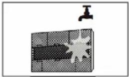
- If your filter has a small air freshening filter, unclip it from the larger filter. Clean this air freshening filter with a hand-held vacuum.
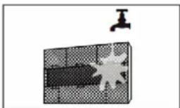
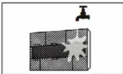
- Clean the large air filter with warm, soapy water. Be sure to use a mild detergent.
- Rinse the filter with fresh water, then shake off excess water.
- Dry it in a cool, dry place, and refrain from exposing it to direct sunlight.
- When dry, re-clip the air freshening filter to the larger filter, then slide it back into the indoor unit.
- Close the front panel of the indoor unit.
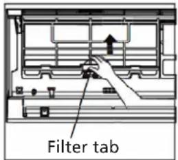
text_image
Filter tab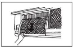
natural_image
Diagram of a hand pressing down a car window with a downward arrow (no text or symbols)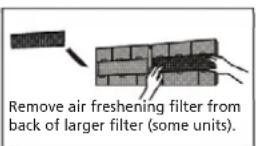
natural_image
Diagram showing a faucet above a textured panel with a starburst pattern (no text or symbols)
CAUTION
Do not touch air freshening (Plasma) filter for at least 10 minutes after turning off the unit.

CAUTION
- Before changing the filter or cleaning, turn off the unit and disconnect its power supply.
- When removing filter, do not touch metal parts in the unit. The sharp metal edges can cut you.
- Do not use water to clean the inside of the indoor unit. This can destroy insulation and cause electrical shock.
- Do not expose filter to direct sunlight when drying. This can shrink the filter panel to deform or become discolored.
Air Filter Reminders (Optional)
Air Filter Cleaning Reminder
After 240 hours of use, the display window on the indoor unit will flash "CL." This is a reminder to clean your filter. After 15 seconds, the unit will revert to its previous display.
To reset the reminder, press the LED button on your remote control 4 times, or press the MANUAL CONTROL button 3 times. If you don't reset the reminder, the "CL" indicator will flash again when you restart the unit.
Air Filter Replacement Reminder
After 2880 hours of use, the display window on the indoor unit will flash "nF." This is a reminder to replace your filter. After 15 seconds, the unit will revert to its previous display.
To reset the reminder, press the LED button on your remote control 4 times, or press the MANUAL CONTROL button 3 times. If you don't reset the reminder, the "nF" indicator will flash again when you restart the unit.

CAUTION
- Any maintenance and cleaning of outdoor unit should be performed by an authorized dealer or a licensed service provider.
- Any unit repairs should be performed by an authorized dealer or a licensed service provider.
Maintenance - Long Periods of Non-Use
If you plan not to use your appliance for an extended period of time, do the following:
natural_image
Diagram of a grid with a small arrow labeled 'H' pointing upward (no text or symbols within the grid)Clean all filters
natural_image
Simple line drawing of a house with waves inside, enclosed in a rounded square frame (no text or symbols)Turn on FAN function until unit dries out completely
text_image
Warning symbol with crossed-out lightning bolt inside a circle, indicating no protection or hazard.Turn off the unit and disconnect the power
natural_image
Simple line drawing of a device with a handle and internal components (no text or symbols)Remove batteries from remote control
Maintenance - Pre-Season Inspection
After long periods of non-use, or before periods of frequent use, do the following:
natural_image
Cross-sectional diagram of a hazard symbol with lightning bolts indicating electrical hazard (no text or labels)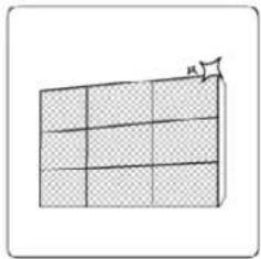
natural_image
Simple 3D grid diagram with a triangular pointer labeled 'A' pointing upward (no text or symbols on the grid itself)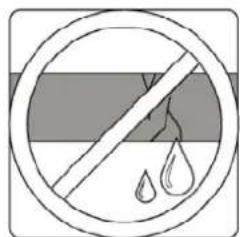
natural_image
Simple line drawing of a crossed-out circle with liquid droplets inside, no text or symbols present.
natural_image
Simple line drawing of a device with a handle and internal components (no text or symbols)Check for damaged wires Clean all filters Check for leaks Replace batteries
Make sure nothing is blocking all air inlets and outlets
D TROUBLESHOOTING

SAFETY PRECAUTIONS
If ANY of the following conditions occurs, turn off your unit immediately!
• The power cord is damaged or abnormally warm
- You smell a burning odor
- The unit emits loud or abnormal sounds
- A power fuse blows or the circuit breaker frequently trips
• Water or other objects fall into or out of the unit
DO NOT ATTEMPT TO FIX THESE YOURSELF! CONTACT AN AUTHORIZED SERVICE PROVIDER IMMEDIATELY!
Common Issues
The following problems are not a malfunction and in most situations will not require repairs.
| Issue Possible Causes | ||
| Unit does not turn on when pressing ON/OFF button | The Unit has a 3-minute protection feature that prevents the unit from overloading. The unit cannot be restarted within three minutes of being turned off. | |
| The unit changes from COOL/HEAT mode to FAN mode | The unit may change its setting to prevent frost from forming on the unit. Once the temperature increases, the unit will start operating in the previously selected mode again. | |
| The set temperature has been reached, at which point the unit turns off the compressor. The unit will continue operating when the temperature fluctuates again. | ||
| The indoor unit emits white mist In humid regions, a large temperature difference between the room's air and the conditioned air can cause white mist. | ||
| Both the indoor and outdoor units emit white mist | When the unit restarts in HEAT mode after defrosting, white mist may be emitted due to moisture generated from the defrosting process. | |
| The indoor unit makes noises A rushing air sound may occur when the louver resets its position. | ||
| A squeaking sound may occur after running the unit in HEAT mode due to expansion and contraction of the unit's plastic parts. | ||
| Both the indoor unit and outdoor unit make noises | Low hissing sound during operation: This is normal and is caused by refrigerant gas flowing through both indoor and outdoor units. | |
| Low hissing sound when the system starts, has just stopped running, or is defrosting: This noise is normal and is caused by the refrigerant gas stopping or changing direction. | ||
| Squeaking sound: Normal expansion and contraction of plastic and metal parts caused by temperature changes during operation can cause squeaking noises. | ||
| The outdoor unit makes noises The unit will make different sounds based on its current operating mode. | ||
| Dust is emitted from either the indoor or outdoor unit | The unit may accumulate dust during extended periods of non-use, which will be emitted when the unit is turned on. This can be mitigated by covering the unit during long periods of inactivity. | |
| The unit emits a bad odor The unit may absorb odors from the environment (such as furniture, cooking, cigarettes, etc.) which will be emitted during operations. | ||
| The fan of the outdoor unit does not operate | During operation, the fan speed is controlled to optimize product operation. | |
| Operation is erratic, unpredictable, or unit is unresponsive | Interference from cell phone towers and remote boosters may cause the unit to malfunction.In this case, try the following:Disconnect the power, then reconnect.Press ON/OFF button on remote control to restart operation. | |
NOTE: If problem persists, contact a local dealer or your nearest customer service center. Provide them with a detailed description of the unit malfunction as well as your model number.
Troubleshooting
When troubles occur, please check the following points before contacting a repair company.
NOTE: If your problem persists after performing the checks and diagnostics above, turn off your unit immediately and contact an authorized service center.
| Problem Possible Causes Solution | ||
| Poor Cooling Performance Temperature setting may be higher than ambient room temperature | Lower the temperature setting | |
| The heat exchanger on the indoor or outdoor unit is dirty | Clean the affected heat exchanger | |
| The air filter is dirty Remove the filter and clean it according to instructions | ||
| The air inlet or outlet of either unit is blocked | Turn the unit off, remove the obstruction and turn it back on | |
| Doors and windows are open Make sure that all doors and windows are closed while operating the unit | ||
| Excessive heat is generated by sunlight | Close windows and curtains during periods of high heat or bright sunshine | |
| Too many sources of heat in the room (people, computers, electronics, etc.) | Reduce amount of heat sources | |
| Low refrigerant due to leak or long-term use | Check for leaks, re-seal if necessary and top off refrigerant | |
| SILENCE function is activated (optional function) | SILENCE function can lower product performance by reducing operating frequency. Turn off SILENCE function. | |
| The unit is not working Power failure | Wait for the power to be restored | |
| The power is turned off Turn on the power | ||
| The fuse is burned out Replace the fuse | ||
| Remote control batteries are dead Replace batteries | ||
| The Unit's 3-minute protection has been activated | Wait three minutes after restarting the unit | |
| Timer is activated Turn timer off | ||
| The unit starts and stops frequently T | There's too much or too little refrigerant in the system | Check for leaks and recharge the system with refrigerant. |
| Incompressible gas or moisture has entered the system. | Evacuate and recharge the system with refrigerant | |
| The compressor is broken Replace the compressor | ||
| The voltage is too high or too low Install a manostat to regulate the voltage | ||
| Poor heating performance The outdoor | oor temperature is extremely low | Use auxiliary heating device |
| Cold air is entering through doors and windows | Make sure that all doors and windows are closed during use | |
| Low refrigerant due to leak or long-term use | Check for leaks, re-seal if necessary and top off refrigerant | |
| Indicator lamps continue flashing The Error code appears and begins with the letters as the following in the window display of indoor unit: E(x), P(x), F(x) EH(xx), EL(xx), EC(xx) PH(xx), PL(xx), PC(xx) | unit may stop operation or continue to run safely. If the indicator lamps continue to flash or error codes appear, wait for about 10 minutes. The problem may resolve itself. If not, disconnect the power, then connect it again. Turn the unit on. If the problem persists, disconnect the power and contact your nearest customer service center. | |
E ACCESSORIES
The air conditioning system comes with the following accessories. Use all of the installation parts and accessories to install the appliance. Improper installation may result in water leakage, electrical shock and fire, or cause the equipment to fail. The items are not included with the appliance must be purchased separately.
| Name of Accessories Qty(pc) Shape | Name of Accessories Q'ty(pc) Shape | ||||
| Manual 2~3 Remote controller 1 |  |  | |||
| Drain joint (for cooling & heating models) | 1 Battery (not included) 2  |  | |||
| Seal (for cooling & heating models) | 1 Remote control  | holder(optional) | 1 |  | |
| Mounting plate 1 Fixing screw for |  | remote controller holder(optional) | 2 |  | |
| Anchor 5~8 | (depen-ding on models) | [6x8T] | Small Filter (Need to be installed on the back of main air filter by the authorized technician while insta-l-ling the machine) | 1~2 (depending on models) |  |
| Mounting plate fixing screw | 5~8 (depen-ding on models) |  | |||
| Name Shape Quantity(PC) | |||
| Connecting pipe assembly | Liquid side Φ6.35( | 1/4 in) Parts you must purchase separately. Consult the dealer about the proper pipe size of the unit you purchased. | |
| Φ9.52( 3/8in) | |||
| Gas side | Φ9.52( 3/8in) | ||
| Φ12.7( 1/2in) | |||
| Φ16( 5/8in) | |||
| Φ19( 3/4in) | |||
| Magnetic ring and belt (if supplied, please refer to the wiring diagram to install it on the connective cable.) | [2x5X]  Pass the belt through the hole of the Magnetic ring to fix it on the cable Pass the belt through the hole of the Magnetic ring to fix it on the cable | Varies by model | |
F INSTALLATION SUMMARY - INDOOR UNIT
text_image
15cm (5.9in) 12cm (4,75in) 12cm (4,75in) 2.3m (90.55in)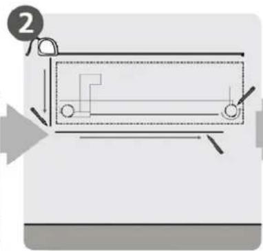
natural_image
Pure technical diagram of a mechanical component with no text, numbers, or symbols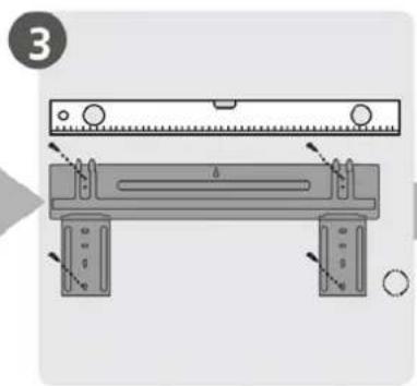
natural_image
Technical diagram of a mechanical assembly with labeled parts, showing a ruler and support structure (no text or symbols present)- Select Installation Location 2. Determine Wall Hole Position 3. Attach Mounting Plate

natural_image
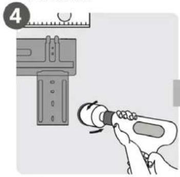
Illustration of a hand using a tool to adjust a component, with no visible text or symbols.- Drill Wall Hole 5. Connect Piping 6. Connect Wiring
natural_image
Illustration of a pipe fitting being adjusted with a forceps, showing rotational motion (no text or symbols)
text_image
6(not applicable for some locations in North America)

natural_image
Illustration of hands holding a black object over a striped cable (no text or symbols)- Prepare Drain Hose
natural_image
Diagram of a cable being inserted into a wire, showing sheath and sheath cross-section (no text or symbols)- Wrap Piping and Cable (not applicable for some locations in North America)
natural_image
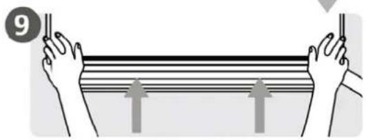
Illustration of two hands holding a rectangular object with horizontal lines and arrows indicating motion or force (no text or symbols)- Mount Indoor Unit
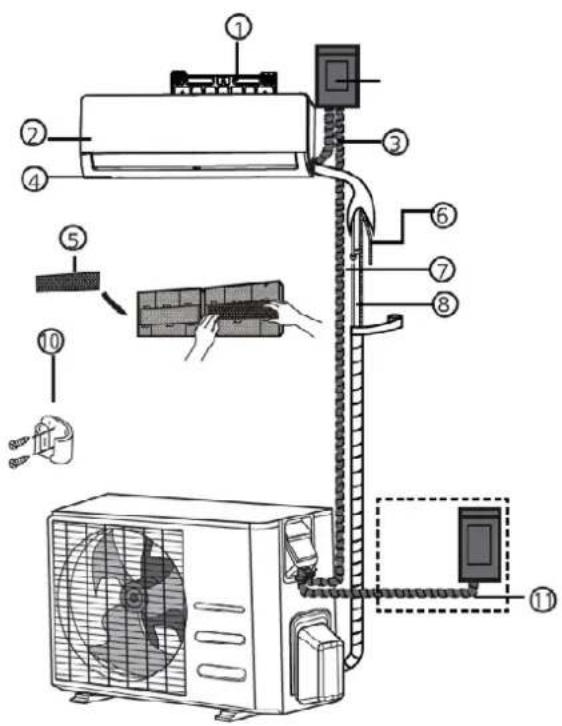
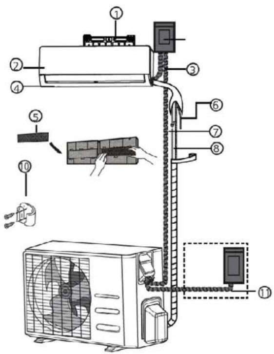
G UNIT PARTS
NOTE: The installation must be performed in accordance with the requirement of local and national standards. The installation may be slightly different in different areas.
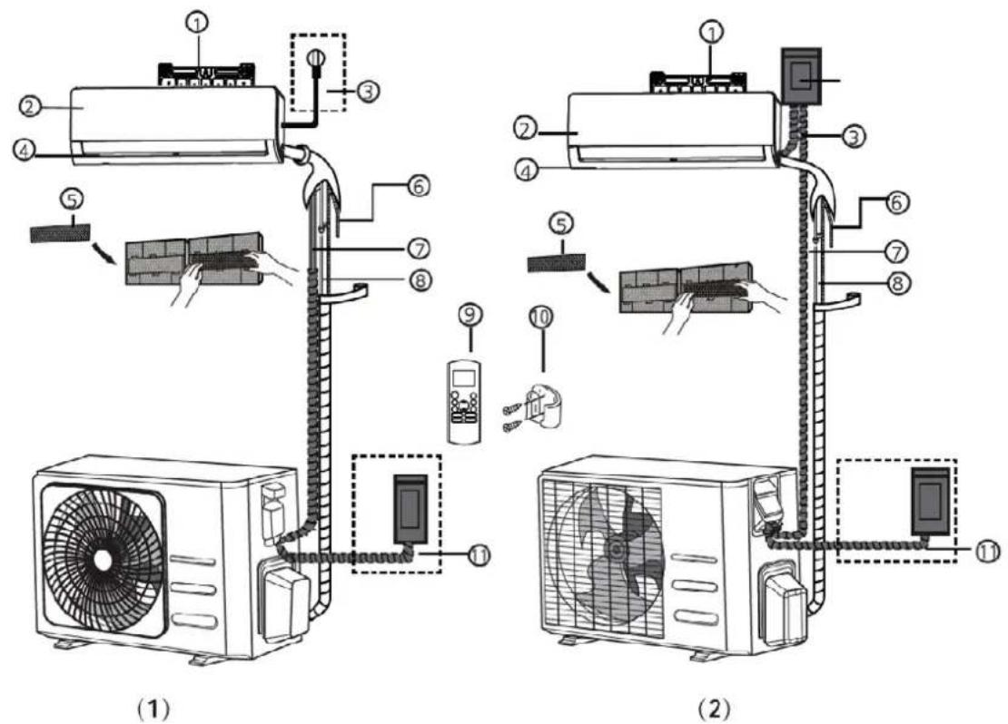
- Wall Mounting Plate 5. Functional Filter (On Back of Main Filter - Same Units) 9. Remote Controller
- Front Panel 6. Drainage Pipe 10. Remote controller Holder (Some Units)
- Power Cable (Some Units) 7. Signal Cable 11. Outdoor Unit Power Cable (Some Units)
- Louver 8. Refrigerant Piping

NOTE ON ILLUSTRATIONS
Illustrations in this manual are for explanatory purposes. The actual shape of your indoor unit may be slightly different. The actual shape shall prevail.
H INDOOR UNIT INSTALLATION
Installation Instructions - Indoor unit
Prior to installation
Before installing the indoor unit, refer to the label on the product box to make sure that the model number of the indoor unit matches the model number of the outdoor unit.
Step 1: Select installation location
Before installing the indoor unit, you must choose an appropriate location. The following are standards that will help you choose an appropriate location for the unit.
Proper installation locations meet the following standards:
• Good air circulation
- Convenient drainage
- Noise from the unit will not disturb other people
- Firm and solid-the location will not vibrate
• Strong enough to support the weight of the unit
- A location at least one meter from all other electrical devices (e.g., TV, radio, computer)
DO NOT install unit in the following locations:
- Near any source of heat, steam, or combustible gas
- Near flammable items such as curtains or clothing
- Near any obstacle that might black air circulation
- Near the doorway
• In a location subject to direct sunlight
NOTE ABOUT WALL HOLE
If there is no fixed refrigerant piping:
While choosing a location, be aware that you should leave ample room for a wall hole (see Drill wall hole for connective piping step) for the signal cable and refrigerant piping that connect the indoor and outdoor units. The default position for all piping is the right side of the indoor unit (while facing the unit). However, the unit can accommodate piping to bath the left and right.
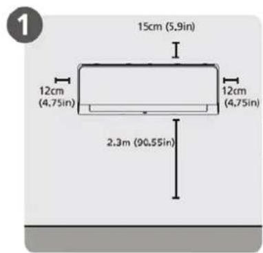
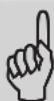
Refer to the following diagram to ensure proper distance from walls and ceiling:
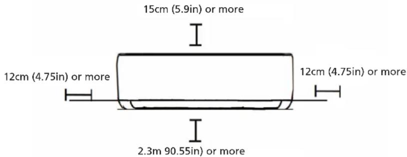
text_image
15cm (5.9in) or more 12cm (4.75in) or more 12cm (4.75in) or more 2.3m 90.55in) or moreStep 2: Attach mounting plate to wall
The mounting plate is the device on which you will mount the indoor unit.
- Remove the screw that attaches the mounting plate to the back of the indoor unit.
natural_image
Technical line drawing of a rectangular electronic component or enclosure with internal compartments (no text or symbols)- Secure the mounting plate to the wall with the screws provided. Make sure that mounting plate is flat against the wall.
NOTE FOR CONCRETE OR BRICK WALLS
If the wall is made of brick, concrete, or similar material, drill 5mm-diameter (0.2in-diameter) holes in the wall and insert the sleeve anchors provided. Then secure the mounting plate to the wall by tightening the screws directly into the clip anchors.
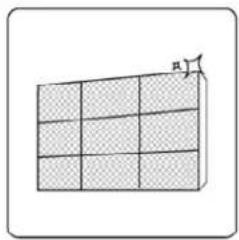
Step 3: Drill wall hole for connective piping
- Determine the location of the wall hole based on the position of the mounting plate. Refer to Mounting Plate Dimensions.
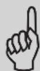
- Using a 65mm (2.5in) or 90mm(3.54in) (depending on models) care drill, drill a hole in the wall. Make sure that the hole is drilled at a slight downward angle, so that the outdoor end of the hole is lower than the indoor end by about 5mm to 7mm (0.2-0.275in). This will ensure proper water drainage.
- Place the protective wall cuff in the hole. This protects the edges of the hole and will help seal it when you finish the installation process.

CAUTION
When drilling the wall hole, make sure to avoid wires, plumbing, and other sensitive components.
text_image
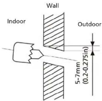
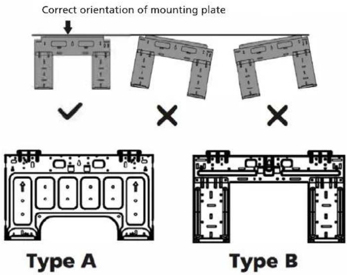
Indoor Wall Outdoor 5-7mm (0.2-0.275in)MOUNTING PLATE DIMENSIONS
Different models have different mounting plates. For the different customization requirements, the shape of the mounting plate may be slightly different.
See Type A and Type B for example:
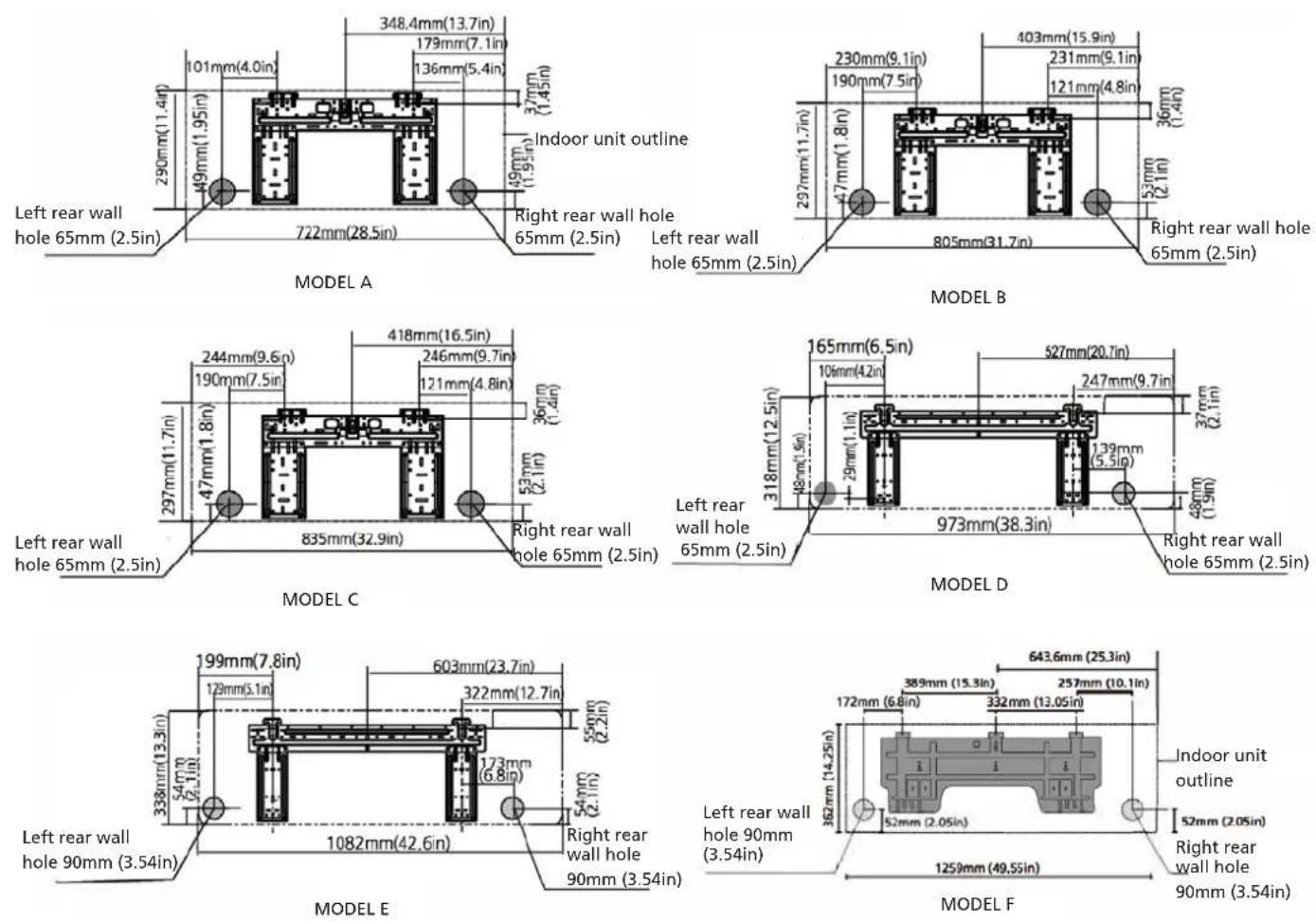
NOTE: When the gas side connective pipe is 16mm(5/8in) or more, the wall hole should be 90mm(3.54in).
Step 4: Prepare refrigerant piping
The refrigerant piping is inside an insulating sleeve attached to the back of the unit. You must prepare the piping before passing it through the hole in the wall.
- Based on the position of the wall hole relative to the mounting plate, choose the side from which the piping will exit the unit.
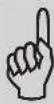
- If the wall hole is behind the unit, keep the knock-out panel in place. If the wall hole is to the side of the indoor unit, remove the plastic knock-out panel from that side of the unit. This will create a slot through which your piping can exit the unit. Use needle nose pliers if the plastic panel is too difficult to remove by hand.
text_image
Knock-out Panel- If existing connective piping is already embedded in the wall, proceed directly to the Connect Drain Hose step. If there is no embedded piping, connect the indoor unit's refrigerant piping to the connective piping that will join the indoor and outdoor units. Refer to the Refrigerant Piping Connection section of this manual for detailed instructions.
NOTE ON PIPING ANGLE
Refrigerant piping can exit the indoor unit from Left-rear side(when you're facing the back of the unit)
natural_image
Technical line drawing of two rectangular electronic devices with internal components and connectors (no text or symbols)
CAUTION
Be extremely careful not to dent or damage the piping while bending them away from the unit. Any dents in the piping will affect the unit's performance.
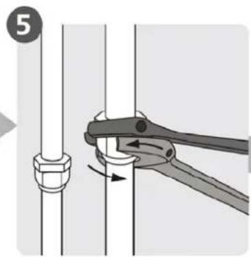
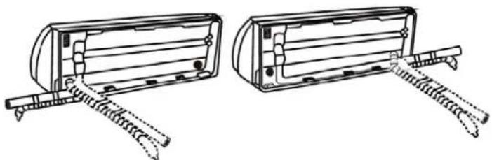
Step 5: Connect drain hose
By default, the drain hose is attached to the left hand side of unit (when you're facing the back of the unit). However, it can also be attached to the right-hand side. To ensure proper drainage, attach the drain hose on the same side that your refrigerant piping exits the unit. Attach drain hose extension (purchased separately) tot the end of the drain hose.
- Wrap the connection point firmly with Teflon tape to ensure a good seal and to prevent leaks.
- For the portion of the drain hose that will remain indoors, wrap it with foam pipe insulation to prevent condensation.
- Remove the air filter and pour a small amount of water into the drain pan to make sure that water flows from the unit smoothly.
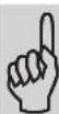
NOTE ON DRAIN HOSE PLACEMENT
Make sure to arrange the drain hose according to the following figures.
natural_image
Simple line drawing of a mechanical joint or bracket with a checkmark (no text or symbols)CORRECT
Make sure there are no kinks ordent in drain hose to ensure proper drainage.
natural_image
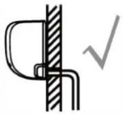
Simple line drawing of a pipe connection with a cross symbol (no text or labels)NOT CORRECT
Kinks in the drain hose will create water traps.
natural_image
Simple line drawing of a wall and ground connection with a cross symbol (no text or labels)NOT CORRECT
Kinks in the drain hose will create water traps.
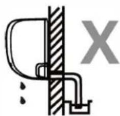
natural_image
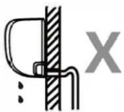
Simple line drawing of a toilet and sink with no text or symbolsNOT CORRECT
Do not place the end of the drain hose in water or in containers that collect water. This will prevent proper drainage.
Plug the unused drain hole
To prevent unwanted leaks you must plug the unused drain hole with the rubber plug provided.
natural_image
Hand holding a cylindrical object with a knife inserted, no visible text or symbols
BEFORE PERFORMING ANY ELECTRICAL WORK, READ THESE REGULATIONS
-
All wiring must comply with local and national electrical codes, regulations and must be installed by a licensed electrician.
-
All electrical connections must be made according to the Electrical Connection Diagram located on the panels of the indoor and outdoor units.
-
If there is a serious safety issue with the power supply, stop work immediately. Explain your reasoning to the dient, and refuse to install the unit until the safety issue is properly resolved.
-
Power voltage should be within 90-110% of rated voltage. Insufficient power supply can cause malfunction, electrical shock, or fire.
-
If connecting power to fixed wiring, a surge protector and main power switch should be installed.
-
If connecting power to fixed wiring, a switch or circuit breaker that disconnects all poles and has a contact separation of at least 1/8in (3mm) must be incorporated in the fixed wiring. The qualified technician must use an approved circuit breaker or switch.
-
Only connect the unit to an individual branch circuit outlet. Do not connect another appliance to that outlet.
-
Make sure to properly ground the appliance.
-
Every wire must be firmly connected. Loose wiring can cause the terminal to overheat, resulting in product malfunction and possible fire.
-
Do not let wires touch or rest against refrigerant tubing, the compressor, or any moving parts with in the unit.
-
If the unit has an auxiliary electric heater, it must be installed at least 1 meter (40in) away from any combustible materials.
-
To avoid getting an electric shock, never touch the electrical components soon after the power supply has been turned off. After turning off the power, always wait 10 minutes or more before you touch the electrical components.

WARNING
Before performing any electrical or wiring work, turn off the main power to the system.
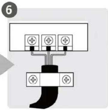
Step 6: Connect signal cable and power cables
The signal cable enables communication between the indoor and outdoor units. You must first choose the right cable size before preparing it for connection.
NOTE: The cable convection of the indoor unit had been finished in the factory.
Cable Types
- Indoor Power Cable (if applicable): H05VV-F or H05V2V2-F
• Outdoor Power Cable: H07RN-F or H05RN-F
• Signal Cable: H07RN-F
Minimum Cross-Sectional Area of Power and Signal Cables (For reference)
| Rated Current of Appliance (A) | Nominal Cross-Sectional Area (mm2) |
| >3 and ≤ 6 0.75 | |
| >6 and ≤ 10 1 | |
| >10 and ≤ 16 1.5 | |
| >16 and ≤ 25 2.5 | |
| >25 and ≤ 32 4 | |
| >32 and ≤ 40 6 |
CHOOSE THE RIGHT CABLE SIZE
The size of the power supply cable, signal cable, fuse, and switch needed is determined by the maximum current of the unit. The maximum current is indicated on the nameplate located on the side panel of the unit. Refer to this nameplate to choose the right cable, fuse, or switch.

WARNING
All wiring must performed strictly in accordance with the wiring diagram located on the back of the indoor unit's front panel.
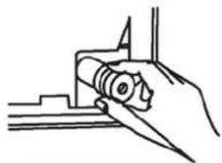
- Open front panel of the indoor unit.
- Using a screwdriver, open the wire box cover on the right side of the unit. This will reveal the terminal block.
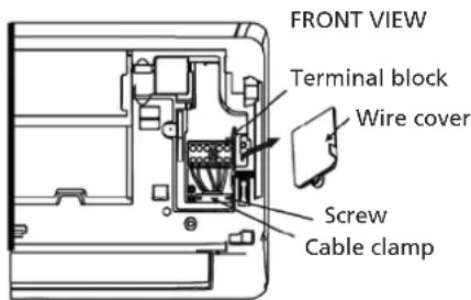
text_image
FRONT VIEW Terminal block Wire cover Screw Cable clamp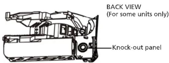
text_image
BACK VIEW (For some units only) Knock-out panelNOTE:
- For the units with conduit tube to connect the cable, remove the big plastic konck-out panel to create a slot through which the conduit tube can be installed.
- For the units with five-core cable, remove the middle small plastic knock-out panel to create a slot through which the cable can exit.
-
Use needle nose pliers if the plastic panel is too difficult to remove by hand.
-
Unscrew the cable clamp below the terminal block and place it to the side.
-
Facing the back of the unit, remove the plastic panel on the bottom left-hand side.
-
Feed the signal wire through this slot, from the back of the unit to the front.
-
Facing the front of the unit, connect the wire according to the indoor unit's wiring diagram, connect the u-lug and firmly screw each wire to its corresponding terminal.

CAUTION
DO NOT MIX UP LIVE AND NULL WIRES.
This is dangerous, and can cause the air conditioning unit to malfunction.
- After checking to make sure every connection is secure, use the cable clamp to fasten the signal cable to the unit. Screw the cable clamp down tightly.
- Replace the wire cover on the front of the unit, and the plastic panel on the back.
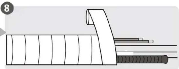
Step 7: Wrappiping and cables
Before passing the piping, drain hose, and the signal cable through the wall hole, you must bundle them together to save space, protect them, and insulate them(Not applicable in North America).
- Bundle the drain hose, refrigerant pipes, and signal cable as shown below:
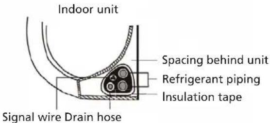
text_image
Indoor unit Spacing behind unit Refrigerant piping Insulation tape Signal wire Drain hoseDRAIN HOSE MUST BE ON BOTTOM
Make sure that the drain hose is at the bottom of the bundle. Putting the drain hose at the top of the bundle can cause the drain pan to overflow, which can lead to fire or water damage.
DO NOT INTERTWINE SIGNAL CABLE WITH OTHER WIRES
While bundling these items together, do not intertwine or cross the signal cable with any other wiring.
- Using adhesive vinyl tape, attach the drain hose to the underside of the refrigerant pipes.
- Using insulation tape, wrap the signal wire, refrigerant pipes, and drain hose tightly together. Double-check that all items are bundled.
DO NOT WRAP ENDS OF PIPING
When wrapping the bundle, keep the ends of the piping unwrapped. You need to access them to test for leaks at the end of the installation process (refer to Electrical Checks and Leak Checks section of this manual).
Step 8: Mount indoor unit
If you installed new connective piping to the outdoor unit.do the following:
- If you have already passed the refrigerant piping through the hole in the wall, proceed to Step 4.
- Otherwise, double-check that the ends of the refrigerant pipes are sealed to prevent dirt or foreign materials from entering the pipes.
- Slowly pass the wrapped bundle of refrigerant pipes, drain hose, and signal wire through the hole in the wall.
- Hook the top of the indoor unit on the upper hook of the mounting plate.
- Check that unit is hooked firmly on mounting by applying slight pressure to the left and right-hand sides of the unit. The unit should not jiggle or shift.
- Using even pressure, push down on the bottom half of the unit. Keep pushing down until the unit snaps onto the hooks along the bottom of the mounting plate.
- Again, check that the unit is firmly mounted by applying slight pressure to the left and the right-hand sides of the unit.
If refrigerant piping is already embedded in the wall, do the following:
- Hook the top of the indoor unit on the upper hook of the mounting plate.
- Use a bracket or wedge to prop up the unit, giving you enough room to connect the refrigerant piping, signal cable, and drain hose.
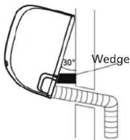
text_image
30° Wedge- Connect drain hose and refrigerant piping (refer to Refrigerant Piping Connection section of this manual for instructions).
- Keep pipe connection point exposed to perform the leak test (refer to Electrical Checks and Leak Checks section of this manual).
- After the leak test, wrap the connection point with insulation tape.
- Remove the bracket or wedge that is propping up the unit.
- Using even pressure, push down on the bottom half of the unit. Keep pushing down until the unit snaps onto the hooks along the bottom of the mounting plate.
UNIT IS ADJUSTABLE
Keep in mind that the hooks on the mounting plate are smaller than the holes on the back of the unit. If you find that you don't have ample room to connect embedded pipes to the indoor unit, the unit can be adjusted left or right by about 30-50mm (1.18-1.96in), depending on the model.
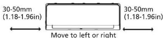
text_image
30-50mm (1.18-1.96in) 30-50mm (1.18-1.96in) Move to left or rightI OUTDOOR UNIT INSTALLATION
Install the unit by following local codes and regulations, there may be differ slightly between different regions.
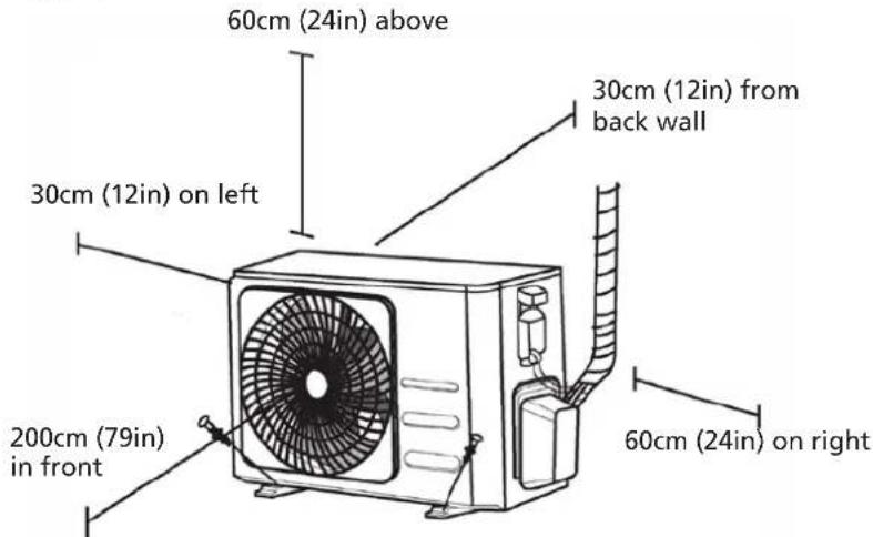
text_image
60cm (24in) above 30cm (12in) on left 30cm (12in) from back wall 200cm (79in) in front 60cm (24in) on rightInstallation Instructions - Outdoor Unit
Step 1: Select installation location
Before installing the outdoor unit, you must choose an appropriate location. The following are standards that will help you choose an appropriate location for the unit.
Proper installation locations meet the following standards:
- Meets all spatial requirements shown in Installation Space Requirements above.
• Good air circulation and ventilation - Firm and solid - the location can support the unit and will not vibrate
• Noise from the unit will not disturb others - Protected from prolonged periods of direct sunlight or rain
- Where snowfall is anticipated, raise the unit above the base pad to prevent ice buildup and coil damage. Mount the unit high enough to be above the average accumulated area snowfall.
• The minimum heigh must be 18 inches
DO NOT install unit in the following locations:
• Near an obstacle that will black air inlets and outlets
- Near a public street, crowded areas, or where noise from the unit will disturb others
• Near animals or plants that will be harmed by hot air discharge
• Near any source of combustible gas
• In a location that is exposed to large amounts of dust
• In a location exposed to a excessive amounts of salty air
If the unit is exposed to heavy wind:
Install unit so that air outlet fan is at a 90° angle to the direction of the wind. If needed, build a barrier in front of the unit to protect it from extremely heavy winds.
See Figures below.
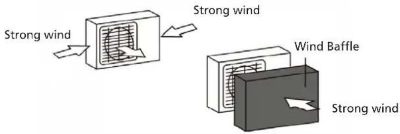
text_image
Strong wind Strong wind Wind Baffle Strong windIf the unit is frequently exposed to heavy rain or snow:
Build a shelter above the unit to protect it from the rain or snow. Be careful not to obstruct air flow around the unit.
If the unit is frequently exposed to salty air (seaside):
Use outdoor unit that is specially designed to resist corrosion.
Step 2: Install drain joint(Heat pump unit only)
Before bolting the outdoor unit in place, you must install the drain joint at the bottom of the unit. Note that there are two different types of drain joints depending on the type of outdoor unit.
If the drain joint comes with a rubber seal (see Fig. A), do the following:
- Fit the rubber seal on the end of the drain joint that will connect to the outdoor unit.
- Insert the drain joint into the hole in the base pan of the unit.
- Rotate the drain joint 90° until it clicks in place facing the front of the unit.
- Connect a drain hose extension (not included) to the drain joint to redirect water from the unit during heating mode.
If the drain joint doesn't come with a rubber seal (see Fig. B), do the following:
- Insert the drain joint into the hole in the base pan of the unit. The drain joint will click in place.
- Connect a drain hose extension (not included) to the drain joint to redirect water from the unit during heating mode.
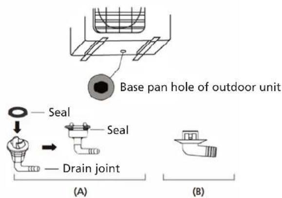
text_image
Base pan hole of outdoor unit Seal Seal Drain joint (A) (B)
IN COLD CLIMATES
In cold climates, make sure that the drain hose is as vertical as possible to ensure swift water drainage. If water drains toa slowly, it can freeze in the hose and flood the unit.
Step 3: Anchor outdoor unit
The outdoor unit can be anchored to the ground or to a wall-mounted bracket with bolt(M10). Prepare the installation base of the unit according to the dimensions below.
UNIT MOUNTING DIMENSIONS
The following is a list of different outdoor unit sizes and the distance between their mounting feet. Prepare the installation base of the unit according to the dimensions below.
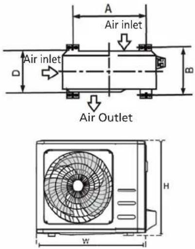
text_image
Air inlet Air inlet Air Outlet A B H W| Outdoor Unit Dimensions (mm) WxHxD Mounting Dimensions Distance A (mm) Mounting Dimensions Distance B (mm) | |
| 681x434x285 (26.8"x17.1"x11.2") 460 (18.1") 292 (11.5") | |
| 700x550x270 (27.5"x21.6"x10.6") 450 (17.7") 260 (10.2") | |
| 700x550x275 (27.5"x21.6"x10.8") 450 (17.7") 260 (10.2") | |
| 720x495x270 (28.3"x19.5"x10.6") 452 (17.8") 255 (10.0") | |
| 728x555x300 (28.7"x21.8"x11.8") 452 (17.8") 302(11.9") | |
| 765x555x303 (30.1"x21.8"x11.9") 452 (17.8") 286(11.3") | |
| 770x555x300 (30.3"x21.8"x11.8") 487 (19.2") 298 (11.7") | |
| 805x554x330 (31.7"x21.8"x12.9") 511 (20.1") 317 (12.5") | |
| 800x554x333 (31.5"x21.8"x13.1") 514 (20.2") 340 (13.4") | |
| 845x702x363 (33.3"x27.6"x14.3") 540 (21.3") 350 (13.8") | |
| 890x673x342 (35.0"x26.5"x13.5") 663 (26.1") 354 (13.9") | |
| 946x810x420 (37.2"x31.9"x16.5") 673 (26.5") 403 (15.9") | |
| 946x810x410 (37.2"x31.9"x16.1") 673 (26.5") 403 (15.9") | |
If you will install the unit on the ground or on a concrete mounting platform, do the following:
- Mark the positions for four expansion balts based on dimensions chart.
- Pre-drill holes for expansion balts.
- Place a nut on the end of each expansion bolt.
- Hammer expansion balts into the pre-drilled holes.
- Remove the nuts from expansion balts, and place outdoor unit on balts.
- Put washer on each expansion bolt, then replace the nuts.
- Using a wrench, tighten each nut until snug.

WARNING
When drilling into concrete, eye protection is recommended at all times.
If you will install the unit on a wall-mounted bracket, do the following:

CAUTION
Make sure that the wall is made of solid brick, concrete, or of similarly strong material. The wall must be able to support at least four times the weight of the unit.
- Mark the position of bracket holes based on dimensions chart.
- Pre-drill the holes for the expansion balts.
- Place a washer and nut on the end of each expansion bolt.
- Thread expansion balts through holes in mounting brackets, put mounting brackets in position, and hammer expansion balts into the wall.
- Check that the mounting brackets are level.
- Carefully lift unit and place its mounting feet on brackets.
- Bolt the unit firmly to the brackets.
- If allowed, install the unit with rubber gaskets to reduce vibrations and noise.
Step 4: Connect signal and power cables
The outside unit's terminal black is protected by an electrical wiring cover on the side of the unit. A comprehensive wiring diagram is printed on the inside of the wiring cover.

WARNING
Before performing any electrical or wiring work, turn off the main power to the system.
- Prepare the cable for connection:
USE THE RIGHT CABLE
Please choose the right cable refer to "Cable types".
CHOOSE THE RIGHT CABLE SIZE
The size of the power supply cable, signal cable, fuse, and switch needed is determined by the maximum current of the unit. The maximum current is indicated on the nameplate located on the side panel of the unit.
a. Using wire strippers, strip the rubber jacket from bath ends of cable to reveal about 40mm (1.57in) of the wires inside.
b. Strip the insulation from the ends of the wires.
c. Using a wire crimper, crimp u-lugs on the ends of the wires.
PAY ATTENTION TO LIVE WIRE
While crimping wires, make sure you dearly distinguish the Live ("L") Wire from other wires.

WARNING
All wiring work must be performed strictly in accordance with the wiring diagram located inside of wire cover of the outdoor unit.
- Unscrew the electrical wiring cover and remove it.
- Unscrew the cable damp below the terminal black and place it to the side.
- Connect the wire according to the wiring diagram, and firmly screw the u-lug of each wire to its corresponding terminal.
- After checking to make sure every connection is secure, loop the wires around to prevent rain water from flowing into the terminal.
- Using the cable damp, tasten the cable to the unit. Screw the cable damp down tightly.
- Insulate unused wires with PVC electrical tape. Arrange them so that they do not touch any electrical or metal parts.
- Replace the wire cover on the side of the unit, and screw it in place.
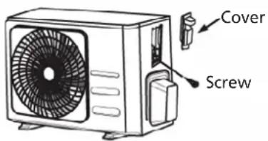
text_image
Cover ScrewNOTE: If the cable damp looks like the following, please select the appropriate through-hole according to the diameter of the wire.
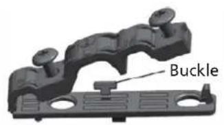
natural_image
Mechanical component labeled 'Buckle' showing a black bracket with mounting holes and a separate flat base (no text or symbols beyond label)Three sizes hole: Small, Large, Medium
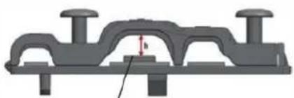
natural_image
Mechanical component diagram showing a bracket with mounting holes and a central hatched area (no text or symbols)When the cable is not fasten enough, use the buckle to prop it up, so it can be clamped tightly.
J REFRIGERANT PIPING CONNECTION
When connecting refrigerant piping, do not let substances or gases other than the specified refrigerant enter the unit. The presence of other gases or substances will lower the unit's capacity, and can cause abnormally high pressure in the refrigeration cycle. This can cause explosion and injury.
Note on Pipe Length
The length of refrigerant piping will affect the performance and energy efficiency of the unit. Nominal efficiency is tested on units with a pipe length of 5 meters (16.5ft)( In North America, the standard pipe length is 7.5m (25')). A minimum pipe run of 3 metres is required to minimise vibration & excessive noise. In special tropical area, for the R290 refrigerant models, no refrigerant can be added and the maximum length of refrigerant pipe should not exceed 10 meters(32.8ft).
Refer to the table below for specifications on the maximum length and drop height of piping.
Maximum Length and Drop Height of Refrigerant Piping per Unit Model
| Model Capacity (BTU/h) Max. Length (m) Max. Drop Height (m) | |||
| R410A,R32 Inverter Split Air Conditioner | < 15,000 25 (82ft) 10 (33ft) | ||
| ≥ 15,000 and < 24,000 30 (98.5ft) 20 (66ft) | |||
| ≥ 24,000 and < 36,000 50 (164ft) 25 (82ft) | |||
| R22 Fixed-speed Split Air Conditioner | < 18,000 10 (33ft) 5 (16ft) | ||
| ≥ 18,000 and < 21,000 15 (49ft) 8 (26ft) | |||
| ≥ 21,000 and < 35,000 20 (66ft) 10 (33ft) | |||
| R410A, R32 Fixed-speed Split Air Conditioner | < 18,000 20 (66ft) 8 (26ft) | ||
| ≥ 18,000 and < 36,000 25 (82ft) 10 (33ft) | |||
Connection Instructions – Refrigerant Piping
Step 1: Cut pipes
When preparing refrigerant pipes, take extra care to cut and flare them properly. This will ensure efficient
operation and minimize the need for future maintenance.
-
Measure the distance between the indoor and outdoor units.
-
Using a pipe cutter, cut the pipe a little longer than the measured distance.
-
Make sure that the pipe is cut at a perfect 90° angle.
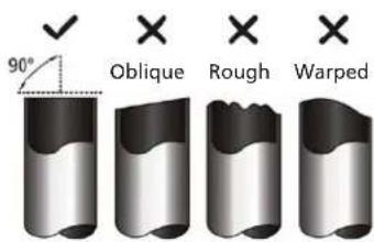
text_image
90° Oblique Rough Warped
DO NOT DEFORM PIPE WHILE CUTTING
Be extra careful not to damage, dent, or deform the pipe while cutting. This will drastically reduce the heating efficiency of the unit.
Step 2: Remove burrs
Burrs can affect the air-tight seal of refrigerant piping connection. They must be completely removed.
- Hold the pipe at a downward angle to prevent burrs from falling into the pipe.
- Using a reamer or deburring tool, remove all burrs from the cut section of the pipe.
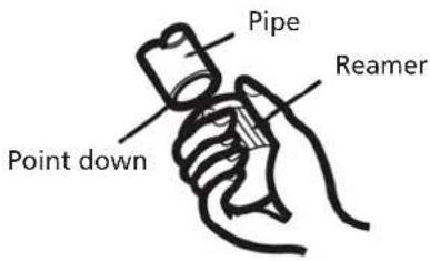
text_image
Pipe Reamer Point downStep 3: Flare pipe ends
Proper flaring is essential to achieve an airtight seal.
- After removing burrs from cut pipe, seal the ends with PVC tape to prevent foreign materials from entering the pipe.
- Sheath the pipe with insulating material.
- Place flare nuts on both ends of pipe. Make sure they are facing in the right direction, because you can't put them on or change their direction after flaring.
- Remove PVC tape from ends of pipe when ready to perform flaring work.
- Clamp flare form on the end of the pipe. The end of the pipe must extend beyond the edge of the flare form in accordance with the dimensions shown in the table below.
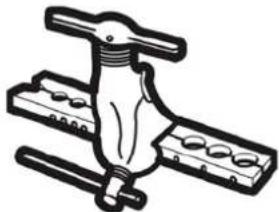
natural_image
Illustration of a mechanical clamp or lever assembly (no text or symbols)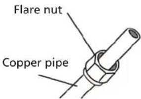
text_image
Flare nut Copper pipePIPING EXTENSION BEYOND FLARE FORM
| Outer Diameter of Pipe (mm) | A (mm) | |
| Min. Max. | ||
| ∅ 6.35 (∅ 0.25") 0.7 (0.0275") 1.3 (0.05") | ||
| ∅ 9.52 (∅ 0.375") 1.0 (0.04") 1.6 (0.063") | ||
| ∅12.7 (∅ 0.5") 1.0 (0.04") 1.8 (0.07") | ||
| ∅ 16 (∅ 0.63") 2.0 (0.078") 2.2 (0.086") | ||
| ∅ 19 (∅ 0.75") 2.0 (0.078") 2.4 (0.094") | ||
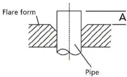
text_image
Flare form A Pipe- Place flaring tool onto the form.
- Turn the handle of the flaring tool clockwise until the pipe is fully flared.
- Remove the flaring tool and flare form, then inspect the end of the pipe for cracks and even flaring.
Step 4: Connect pipes
When connecting refrigerant pipes, be careful not to use excessive torque or to deform the piping in any way. You should first connect the low-pressure pipe, then the high-pressure pipe.
MINIMUM
BEND
RADIUS
When bending connective refrigerant piping, the minimum bending radius is 10cm.
Instructions for Connecting Piping to Indoor Unit
- Align the center of the two pipes that you will connect.
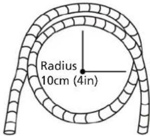
text_image
Radius 10cm (4in)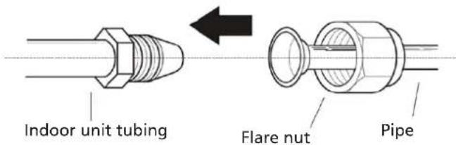
text_image
Indoor unit tubing Flare nut Pipe-
Tighten the flare nut as tightly as possible by hand.
-
Using a spanner, grip the nut on the unit tubing.
-
While firmly gripping the nut on the unit tubing, use a torque wrench to tighten the flare nut according to the torque values in the Torque Requirements table below. Loosen the flaring nut slightly, then tighten again.
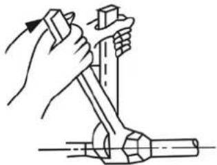
natural_image
Illustration of a hand using a tool to lift a cylindrical object (no text or symbols present)TORQUE REQUIREMENTS
| Outer Diameter of Pipe (mm) | Tightening Torque (N•m) | Flare dimension(B) (mm) | Flare shape |
| ∅ 6.35 (∅ 0.25") 18~20(180 | ~200kgf.cm) 8.4~8.7 (0.33~0.34") | 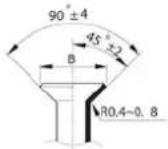 | |
| ∅ 9.52 (∅ 0.375") 32~39(32 | 0~390kgf.cm) 13.2~13.5 (0.5 | 2~0.53") | |
| ∅ 12.7 (∅ 0.5") 49~59(490~ | 590kgf.cm) 16.2~16.5 (0.64~0.65") | ||
| ∅ 16 (∅ 0.63") 57~71(570~ | 710kgf.cm) 19.2~19.7 (0.76~0.78") | ||
| ∅ 19 (∅ 0.75") 67~101(670~ | 1010kgf.cm) 23.2~23.7 (0.9 | 1~0.93") | |

DO NOT USE EXCESSIVE TORQUE
Excessive force can break the nut or damage the refrigerant piping. You must not exceed torque requirements shown in the table above.
Instructions for Connecting Piping to Outdoor Unit
-
Unscrew the cover from the packed valve on the side of the outdoor unit.
-
Remove protective caps from ends of valves.
-
Align flared pipe end with each valve, and tighten the flare nut as tightly as possible by hand.
-
Using a spanner, grip the body of the valve. Do not grip the nut that seals the service valve.
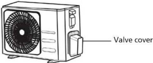
text_image
Valve cover-
While firmly gripping the body of the valve, use a torque wrench to tighten the flare nut according to the correct torque values.
-
Loosen the flaring nut slightly, then tighten again.
- Repeat Steps 3 to 6 for the remaining pipe.
USE SPANNER TO GRIP MAIN BODY OF VALVE
Torque from tightening the flare nut can snap off other parts of valve.
AIR EVACUATION
Preparations and Precautions
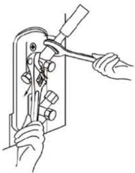
natural_image
Line drawing of hands using a tool to adjust or install a mechanical component (no text or symbols present)Air and foreign matter in the refrigerant circuit can cause abnormal rises in pressure, which can damage the appliance, reduce its efficiency, and cause injury. Use a vacuum pump and manifold gauge to evacuate the refrigerant circuit, removing any non-condensable gas and moisture from the system.
Evacuation should be performed upon initial installation and when unit is relocated.
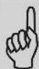
BEFORE PERFORMING EVACUATION
- Check to make sure the connective pipes between the indoor and outdoor units are connected properly.
- Check to make sure all wiring is connected properly.
Evacuation Instructions
- Connect the charge hose of the manifold gauge to service port on the outdoor unit's low pressure valve.
- Connect another charge hose from the manifold gauge to the vacuum pump.
- Open the Low Pressure side of the manifold gauge. Keep the High Pressure side closed.
- Turn on the vacuum pump to evacuate the system.
- Run the vacuum for at least 15 minutes, or until the Compound Meter reads -76cmHG (-10 Pa).
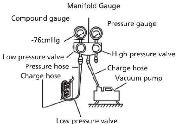
text_image
Manifold Gauge Compound gauge -76cmHg Pressure gauge High pressure valve Low pressure valve Pressure hose Charge hose Vacuum pump Low pressure valve- Close the Low Pressure side of the manifold gauge, and turn off the vacuum pump.
- Wait for 5 minutes, then check that there has been no change in system pressure.
- If there is a change in system pressure, refer to Gas Leak Check section for information on how to check for leaks. If there is no change in system pressure, unscrew the cap from the packed valve (high pressure valve).
-
Insert hexagonal wrench into the packed valve (high pressure valve) and open the valve by turning the wrench in a 1/4 counterclockwise turn. Listen for gas to exit the system, then close the valve after 5 seconds.
-
Watch the Pressure Gauge for one minute to make sure that there is no change in pressure. The Pressure Gauge should read slightly higher than atmospheric pressure.
-
Remove the charge hose from the service port.
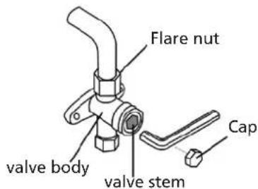
text_image
Flare nut valve body valve stem Cap-
Using hexagonal wrench, fully open both the high pressure and low pressure valves.
-
Tighten valve caps on all three valves (service port, high pressure, low pressure) by hand. You may tighten it further using a torque wrench if needed.

OPEN VALVE STEMS GENTLY
When opening valve stems, turn the hexagonal wrench until it hits against the stopper. Do not try to force the valve to open further.
NOTE ON ADDING REFRIGERANT
Some systems require additional charging depending on pipe lengths. The standard pipe length varies according to local regulations. For example, in North America, the standard pipe length is 7.5m (25'). In other areas, the standard pipe length is 5m (16'). The refrigerant should be charged from the service port on the outdoor unit's low pressure valve. The additional refrigerant to be charged can be calculated using the following formula:
ADDITIONAL REFRIGERANT PER PIPE LENGTH
| Connective Pipe Length (m) | Air Purging Method | Additional Refrigerant | |
| < Standard pipe length Vacuum Pump | N/A | ||
| >Standard pipe length | Vacuum Pump | Liquid Side: ∅ 6.35 (ø 0.25") Liquid Side: ∅ 9.52 (ø 0.375") | |
| R32:(Pipe length - standard length) x 12g/m(Pipe length - standard length) x 0.13oZ/ft | R32:(Pipe length - standard length) x 24g/m(Pipe length - standard length) x 0.26oZ/ft | ||
| R290:(Pipe length - standard length) x 10g/m(Pipe length - standard length) x 0.10oZ/ft | R290:(Pipe length - standard length) x 18g/m(Pipe length - standard length) x 0.19oZ/ft | ||
| R410A:(Pipe length - standard length) x 15g/m(Pipe length - standard length) x 0.16oZ/ft | R410A:(Pipe length - standard length) x 30g/m(Pipe length - standard length) x 0.32oZ/ft | ||
| R22:(Pipe length - standard length) x 20g/m(Pipe length - standard length) x 0.21oZ/ft | R22:(Pipe length - standard length) x 40g/m(Pipe length - standard length) x 0.42oZ/ft | ||
For R290 refrigerant unit, the total amount of refrigerant to be charged is no more than: 387g (<=9000-tu/h), 447g(>9000Btu/h and <=12000Btu/h), 547g(>12000Btu/h and <=18000Btu/h), 632g(>18000Btu/h and <=24000Btu/h).

CAUTION
DO NOT mix refrigerant types.
K ELECTRICAL AND GAS LEAK CHECKS
Before Test Run
Only perform test run after you have completed the following steps:
- Electrical Safety Checks - Confirm that the unit's electrical system is safe and operating properly
- Gas Leak Checks- Check all flare nut connections and confirm that the system is not leaking
- Confirm that gas and liquid (high and low pressure) valves are fully open
Electrical Safety Checks
After installation, confirm that all electrical wiring is installed in accordance with local and national regulations, and according to the Installation Manual.
BEFORE TEST RUN
Check Grounding Work
Measure grounding resistance by visual detection and with grounding resistance tester. Grounding resistance must be less than 0.10.
NOTE: This may not be required for some locations in the US.
DURING TEST RUN
Check for Electrical Leakage
During the Test Run, use an electroprobe and multimeter to perform a comprehensive electrical leakage test.
If electrical leakage is detected, turn off the unit immediately and call a licensed electrician to find and resolve the cause of the leakage.
NOTE: This may not be required for some locations in the US.
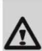
WARNING - RISK OF ELECTRIC SHOCK
All wiring must comply with local and national electrical codes, and must be installed by a licensed electrician.
Gas Leak Checks
There are two different methods to check for gas leaks.
Soap and Water Method
Using a soft brush, apply soapy water or liquid detergent to all pipe connection points on the indoor unit and outdoor unit. The presence of bubbles indicates a leak.
Leak Detector Method
If using leak detector, refer to the device's operation manual for proper usage instructions.
AFTER PERFORMING GAS LEAK CHECKS
After confirming that the all pipe connection points DO NOT leak, replace the valve cover on the outside unit.
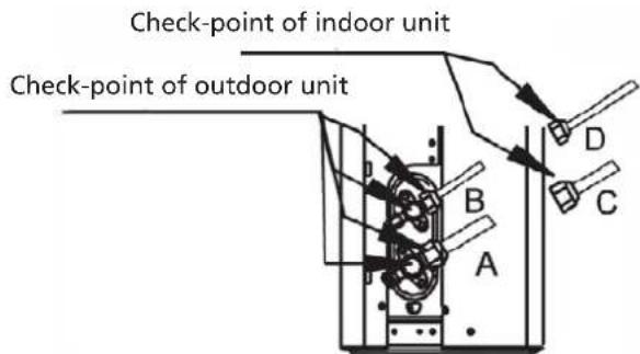
text_image
Check-point of indoor unit Check-point of outdoor unit A B C DA: Low pressure stop valve
B: High pressure stop valve
C& D: Indoor unit flare nuts
L TEST RUN
Test Run Instructions
You should perform the Test Run for at least 30 minutes.
- Connect power to the unit.
- Press the ON/OFF button on the remote controller to turn it on.
- Press the MODE button to serial through the following functions, one at a time:
• COOL- Select lowest possible temperature
• HEAT - Select highest possible temperature
- Let each function run for 5 minutes, and perform the following checks:
| List of Checks to Perform PASS / FAIL | ||
| No electrical leakage | ||
| Unit is properly grounded | ||
| All electrical terminals properly covered | ||
| Indoor and outdoor units are solidly installed | ||
| All pipe connection points do not leak Outdoor (2): Indoor (2): | ||
| Water drains properly from drain hose | ||
| All piping is properly insulated | ||
| Unit performs COOL function properly | ||
| Unit performs HEAT function properly | ||
| Indoor unit louvers rotate properly | ||
| Indoor unit responds to remote controller | ||
DOUBLE-CHECK PIPE CONNECTIONS
During operation, the pressure of the refrigerant circuit will increase. This may reveal leaks that were not present during your initial leak check. Take time during the Test Run to double-check that all refrigerant pipe connection points do not have leaks. Refer to Gas Leak Check section for instructions.
- After the Test Run is successfully completed, and you confirm that all checks points in List of Checks to Perform have PASSED, do the following:
a. Using remote control, return unit to normal operating temperature.
b. Using insulation tape, wrap the indoor refrigerant pipe connections that you left uncovered during the indoor unit installation process.
IF AMBIENT TEMPERATURE IS BELOW 16°C (60°F)
You can't use the remote controller to turn on the COOL function when the ambient temperature is below 16^ C. In this instance, you can use the MANUAL CONTROL button to test the COOL function.
- Lift the front panel of the indoor unit, and raise it until it clicks in place.
- The MANUAL CONTROL button is located on the right-hand side of the unit. Press it 2 times to select the COOL function.
- Perform Test Run as normal.
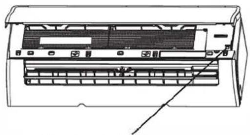
natural_image
Technical line drawing of an air conditioner unit with ventilation grilles and a handle (no text or symbols)Manual control button
M GUARANTEE CONDITIONS
The appliance is supplied with a 48-month guarantee on the compressor and a 24-month guarantee on other components, commencing on the date of purchase. The following rules apply:
- We expressly refuse all further damage claims, including claims for collateral damage.
- Repairs to or replacement of components within the guarantee period will not result in an extension of the guarantee.
- The guarantee is invalidated if any modifications have been made, non genuine parts are fitted or repairs are carried out by third parties.
- Components subject to normal wear, such as the filter, are not covered by the guarantee.
- The guarantee is valid only when you present the original, dated purchase invoice and if no modifications have been made.
- The guarantee is invalid for damage caused by neglect or by actions that deviate from those in this instruction booklet.
- Transportation costs and the risks involved during the transportation of the appliance or appliance components shall always be for the account of the purchaser.
- Damage caused by not using suitable filters is not covered by the guarantee.
- Refrigerant loss and/or leakage because of incompetent (dis)connecting of the units and/or (dis-) connection of the units by not qualified personnel is not covered by the guarantee conditions applicable to this product. Damage to units which are mounted, connected and/or disconnected not following local law and/or legislation and/or not following the guidelines in this manual is not covered by the guarantee conditions applicable to this product.
Consult your dealer for repairs if these instructions do not provide a solution. Make sure that in the unlikely case of needed disconnection, that disconnection is always done by qualified, authorized personnel and according to your local laws and legislation.

Do not dispose of electrical appliances as unsorted municipal waste, use separate collection facilities. Contact your local government for information regarding the collection systems available. If electrical appliances are disposed of in landfills or dumps, hazardous substances can leak into the groundwater and get into the food chain, damaging your health and well-being. When replacing old appliances with new once, the retailer is legally obligated to take back your old appliance for disposal at least for free of charge. Do not throw batteries into the fire, where they can explode or release dangerous liquids. If you replace or destroy the remote control, remove the batteries and throw them away in accordance with the applicable regulations because they are harmful to the environment.
Environmental information: This equipment contains fluorinated greenhouse gases covered by the Kyoto Protocol. It should only be serviced or dismantled by professional trained personnel.
This equipment contains R32 refrigerant in the amount as stated in the table above. Do not vent R32 into atmosphere: R32, is a fluorinated greenhouse gas with a Global Warming Potential (GWP) = 675
Internet:
For your convenience you can download the latest version of the user-, installation- and/or service manual on www.Qlima.com
Gentile signora, egregio signore,
natural_image
Simple line drawing of a vehicle under a roof structure with no text or symbols
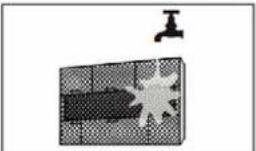
natural_image
Diagram showing a water tap above a grid-patterned object with a starburst effect (no text or symbols)
ATTENZIONE
natural_image
Simple line drawing of a grid with a small triangular pointer on top (no text or symbols)natural_image
Simple line drawing of a house with wavy roof and window (no text or symbols)text_image
Prohibition sign with a circular symbol containing a crossed-out lightning bolt and lightning boltsnatural_image
Simple line drawing of a smartphone with a cable inserted into the screen (no text or symbols)natural_image
Cross-sectional diagram of a hazard symbol with lightning bolts indicating electrical hazard (no text or labels)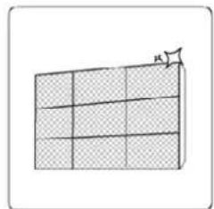
natural_image
Simple line drawing of a grid with a flag icon (no text or symbols)
natural_image
Simple diagram of a crossed-out ring with liquid droplets inside, no text or symbols present.
natural_image
Simple line drawing of a handheld device with a handle and internal components (no text or symbols)natural_image
Pure technical diagram of a mechanical component with no text, numbers, or symbolsnatural_image
Technical diagram of a mechanical assembly with no visible text or symbolsnatural_image
Diagram showing a pipe clamp securing a bolt, with motion arrows indicating movement (no text or symbols)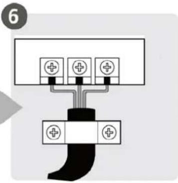
text_image
6natural_image
Illustration of hands holding a black object over a wavy line (no text or symbols)natural_image
Diagram of a cable being inserted into a wire, showing sheath and sheath with no text or symbolsnatural_image
Illustration of hands holding a long object with three upward arrows indicating motion or force (no text or symbols)text_image
Diagram of an air conditioner system with numbered components and labeled parts for installation or maintenance.(1)
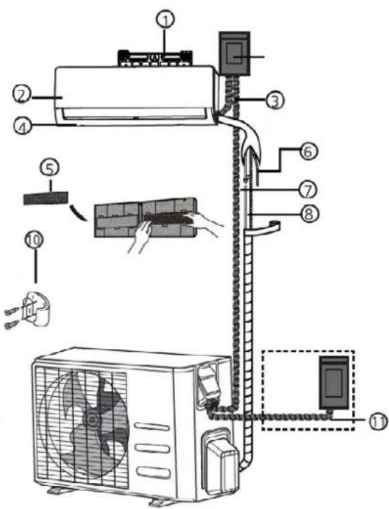
text_image
Diagram of an air conditioner system with numbered components and installation steps(2)
natural_image
Technical line drawing of a rectangular electronic component or enclosure with internal compartments (no text or symbols)natural_image
Technical line drawing of two rectangular electronic components with coiled leads and connectors (no text or symbols)
ATTENZIONE
natural_image
Simple line drawing of a mechanical joint or bracket with a checkmark (no text or symbols)CORRETTO
natural_image
Simple line drawing of a mechanical joint or bracket with a cross symbol (no text or labels)ERRATO
natural_image
Simple line drawing of a pipe connection with a wall and ground, no text or symbols presentERRATO:
natural_image
Simple line drawing of a pipe connection with a wall and a cross symbol (no text or labels)ERRATO:
natural_image
Line drawing of a hand holding a cylindrical object with a knife inserted (no text or symbols)
PRIMA DI EFFETTUARE QUALSIASI INTERVENTO ELETTRICO, LEGGERE QUESTE REGOLE
natural_image
Technical line drawing of a front-end air conditioner unit with fan and ventilation grille (no text or symbols)| Dimensioni dell'unità esterna (mm)WxHxD | Dimensioni di montaggio distanza A (mm) | Dimensioni di montaggio distanza B (mm) |
| 681x434x285 (26.8"x17.1"x11.2") 460 (18.1") 292 (11.5") | ||
| 700x550x270 (27.5"x21.6"x10.6") 450 (17.7") 260 (10.2") | ||
| 700x550x275 (27.5"x21.6"x10.8") 450 (17.7") 260 (10.2") | ||
| 720x495x270 (28.3"x19.5"x10.6") 452 (17.8") 255 (10.0") | ||
| 728x555x300 (28.7"x21.8"x11.8") 452 (17.8") 302(11.9") | ||
| 765x555x303 (30.1"x21.8"x11.9") 452 (17.8") 286(11.3") | ||
| 770x555x300 (30.3"x21.8"x11.8") 487 (19.2") 298 (11.7") | ||
| 805x554x330 (31.7"x21.8"x12.9") 511 (20.1") 317 (12.5") | ||
| 800x554x333 (31.5"x21.8"x13.1") 514 (20.2") 340 (13.4") | ||
| 845x702x363 (33.3"x27.6"x14.3") 540 (21.3") 350 (13.8") | ||
| 890x673x342 (35.0"x26.5"x13.5") 663 (26.1") 354 (13.9") | ||
| 946x810x420 (37.2"x31.9"x16.5") 673 (26.5") 403 (15.9") | ||
| 946x810x410 (37.2"x31.9"x16.1") 673 (26.5") 403 (15.9") |
natural_image
3D mechanical component diagram showing a bracket with mounting holes and a central shaft (no text or symbols)natural_image
Technical line drawing of a mechanical clamp or fixture with three plates and a handle (no text or symbols)ESTENSIONE TUBO OLTRE LA FORMA SVASATA
| Diámetro exterior del tubo (mm) | A (mm) | |
| Min. Max. | ||
| ∅ 6.35 (∅ 0.25") 0.7 (0.0275") 1.3 (0.05") | ||
| ∅ 9.52 (∅ 0.375") 1.0 (0.04") 1.6 (0.063") | ||
| ∅12.7 (∅ 0.5") 1.0 (0.04") 1.8 (0.07") | ||
| ∅ 16 (∅ 0.63") 2.0 (0.078") 2.2 (0.086") | ||
| ∅ 19 (∅ 0.75") 2.0 (0.078") 2.4 (0.094") | ||
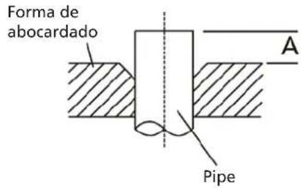
text_image
Forma de abocardado A Pipetext_image
Radio 10 cm (4in)natural_image
Illustration of a hand using a tool to lift a cylindrical object (no text or symbols present)REQUISITI DI COPPIA
| Diametro esterno del tubo (mm) | Coppia di serraggio (N•m) | Dimensione della svasatura(B) (mm) | Forma della svasatura |
| ∅ 6.35 (∅ 0.25") 18~20(180 | ~200kgf.cm) 8.4~8.7 (0.33~0.34") | 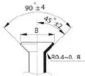 | |
| ∅ 9.52 (∅ 0.375") 32~39(32 | 0~390kgf.cm) 13.2~13.5 (0.52~0.53") | ||
| ∅ 12.7 (∅ 0.5") 49~59(490~ | 590kgf.cm) 16.2~16.5 (0.64~0.65") | ||
| ∅ 16 (∅ 0.63") 57~71(570~ | 710kgf.cm) 19.2~19.7 (0.76~0.78") | ||
| ∅ 19 (∅ 0.75") 67~101(670~ | 1010kgf.cm) 23.2~23.7 (0.91~0.93") | ||

NON USARE UNA COPPIA ECCESSIVA
natural_image
Line drawing of hands using a manual tool to adjust or install a mechanical component (no text or symbols present)Only perform test run after you have completed the following steps:
- Electrical Safety Checks - Confirm that the unit's electrical system is safe and operating properly
- Gas Leak Checks- Check all flare nut connections and confirm that the system is not leaking
- Confirm that gas and liquid (high and low pressure) valves are fully open
Electrical Safety Checks
After installation, confirm that all electrical wiring is installed in accordance with local and national regulations, and according to the Installation Manual.
BEFORE TEST RUN
Check Grounding Work
Measure grounding resistance by visual detection and with grounding resistance tester. Grounding resistance must be less than 0.10.
NOTE: This may not be required for some locations in the US.
DURANTE LA PROVA
natural_image
Line drawing of an air conditioner unit with ventilation slots and a handle (no text or symbols)Pulsante Manual control
WAARSCHUWINGEN VOOR DE INSTALLATIE VAN HET PRODUCT
natural_image
Simple line drawing of a garage with a patterned door and window (no text or symbols)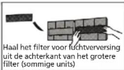
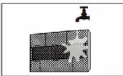
natural_image
Diagram showing a faucet above a textured rectangular object with a starburst pattern (no text or symbols)
OPGELET
natural_image
Simple 3D grid diagram with a small arrow pointing to the top-right corner (no text or symbols)natural_image
Simple line drawing of a house with wavy lines inside, enclosed in a rounded square (no text or symbols)VENTILATOR in tot de unit volledig droog is
text_image
Warning symbol with crossed-out lightning bolt inside a circle, indicating no protection or resistance.natural_image
Simple line drawing of a device with a handle and internal components (no text or symbols)natural_image
Cross-sectional diagram of a device with lightning bolts indicating electrical hazard (no text or symbols)natural_image
Diagram of a grid structure with hatched fill and an arrow indicating direction (no text or symbols)natural_image
Simple diagram showing a circular frame with a diagonal line crossing a shaded rectangle, and two droplet symbols inside (no text or labels)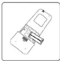
natural_image
Simple line drawing of a device with a handle and internal components (no text or symbols)
natural_image
Pure diagram of a mechanical component with no text, numbers, or symbolsnatural_image
Technical diagram of a mechanical assembly with labeled components and alignment indicators (no readable text or symbols)natural_image
Diagram showing a tool interacting with a mechanical component, no text or symbols presentnatural_image
Illustration of hands holding a black object over a textured surface (no text or symbols)natural_image
Diagram of a cable being inserted into a wire, showing sheath and sheath cross-section (no text or symbols)natural_image
Illustration of hands holding a long object with three arrows indicating motion or force direction (no text or symbols)- De binnenunit monteren
G ONDERDELEN VAN DE UNIT
text_image
Diagram of an air conditioner system with numbered components including air conditioner, wall-mounted panel, and fan unit(1)

text_image
Diagram of an air conditioner system with numbered components and installation steps(2)
H INSTALLATIE BINNENUNIT
natural_image
Technical line drawing of a rectangular device with internal compartments and mounting holes (no text or symbols)text_image
Diagram showing three mechanical assembly states with check and cross symbols indicating selection or failure.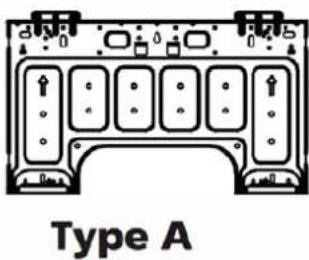
text_image
Type A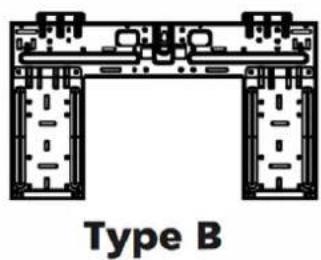
text_image
Type B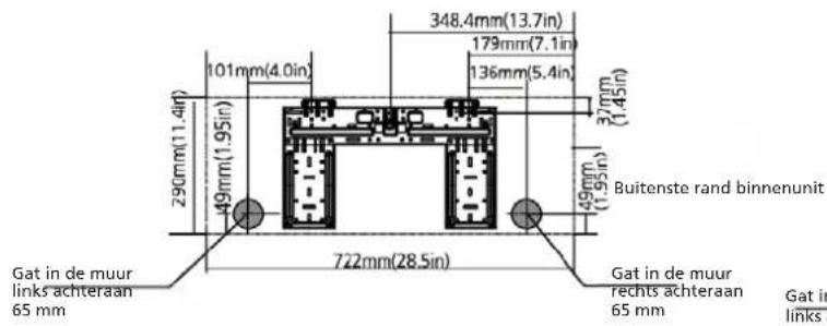
text_image
348.4mm(13.7in) 179mm(7.1in) 136mm(5.4in) 37mm (1.45in) 290mm(11.4in) 101mm(4.0in) 49mm(1.95in) Buitenste rand binnenunit 722mm(28.5in) Gat in de muur links achteraan 65 mm Gat in de muur rechts achteraan 65 mm Gat in links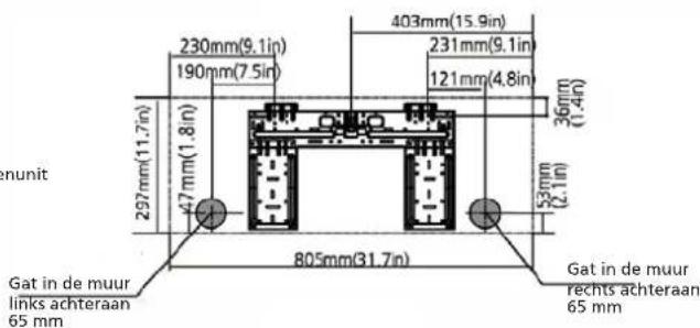
text_image
230mm(9.1in) 190mm(7.5in) 403mm(15.9in) 231mm(9.1in) 121mm(4.8in) 36mm(1.4in) 297mm(11.7in) 47mm(1.8in) 805mm(31.7in) Gat in de muur links achteraan 65 mm Gat in de muur rechts achteraan 65 mm nunit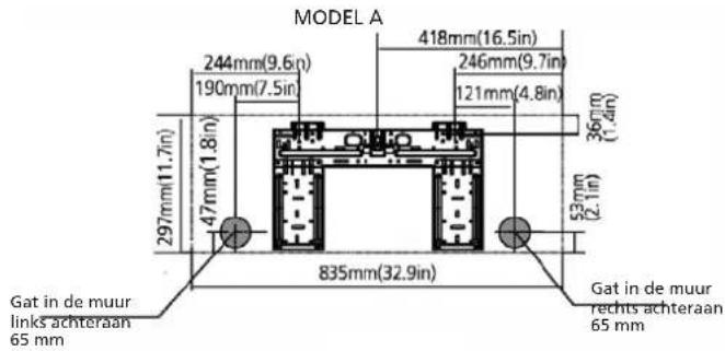
text_image
MODEL A 244mm(9.6in) 190mm(7.5in) 47mm(1.8in) 297mm(11.7in) 835mm(32.9in) 418mm(16.5in) 246mm(9.7in) 121mm(4.8in) 360mm(1.4in) 52mm(2.1in) Gat in de muur links achteraan 65 mm Gat in de muur rechts achteraan 65 mm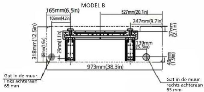
text_image
MODEL B 165mm(6.5in) 527mm(20.7in) 106mm(4.2in) 247mm(9.7in) 318mm(12.5in) 37mm(2.1in) 29mm(1.1in) 1.39mm(5.5in) 48mm(1.9in) 318mm(12.5in) 973mm(38.3in) Gat in de muur links achteraan 65 mm Gat in de muur rechts achteraan 65 mm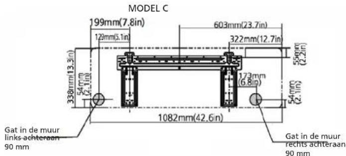
text_image
MODEL C 199mm(7.8in) 603mm(23.7in) 129mm(5.1in) 322mm(12.7in) 55mm (2.2in) 338mm(13.3in) 54mm (2.1in) 173mm (6.8in) 54mm (2.1in) 1082mm(42.6in) Gat in de muur links achteraan 90 mm Gat in de muur rechts achteraan 90 mm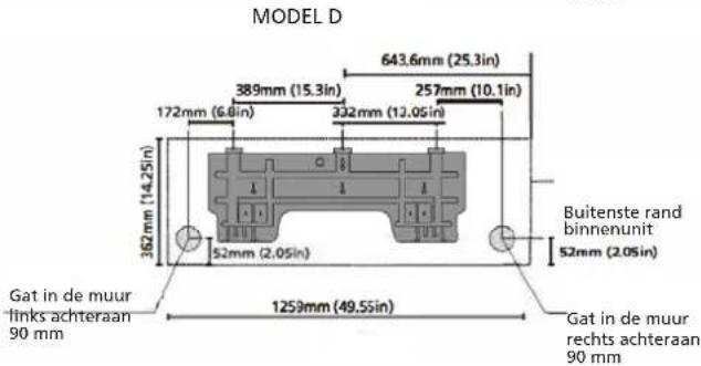
text_image
MODEL D 643.6mm (25.3in) 389mm (15.3in) 257mm (10.1in) 172mm (6.8in) 332mm (10.05in) 362mm (14.25in) 52mm (2.05in) Buitenste rand binnenunit 52mm (2.05in) Gat in de muur links achteraan 90 mm 1259mm (49,55in) Gat in de muur rechts achteraan 90 mmnatural_image
Line drawings of two rectangular electronic devices with coiled leads and internal components (no text or symbols)
OPGELET
natural_image
Simple line drawing of a mechanical joint or bracket with a checkmark (no text or symbols)JUIST
natural_image
Simple line drawing of a mechanical joint or bracket with a cross symbol (no text or labels)NIET JUIST
natural_image
Simple line drawing of a wall and ground connection with a cross symbol (no text or labels)NIET JUIST
natural_image
Simple line drawing of a pipe connection with a cross symbol (no text or labels)NIET JUIST
natural_image
Line drawing of a hand holding a cylindrical object with a pointed tip, against a plain background (no text or symbols)
text_image
30-50 mm 30-50 mmINSTALLATIE BUITENUNIT
natural_image
Mechanical component with labeled Gesp part (no other text or symbols visible)natural_image
3D mechanical component diagram showing a bracket with mounting holes and a central base (no text or symbols)natural_image
Illustration of a faucet with multiple base plates (no text or symbols)VERLENGING VAN DE LEIDING VOORBIJ DE FLENSVORM
| Buitendiameter van de leiding (mm) | A (mm) | |
| Min. Max. | ||
| ∅ 6,35 (∅ 0,25") 0,7 (0,0275") 1,3 (0,05") | ||
| ∅ 9,52 (∅ 0,375") 1,0 (0,04") 1,6 (0,063") | ||
| ∅12,7 (∅ 0,5") 1,0 (0,04") 1,8 (0,07") | ||
| ∅ 16 (∅ 0,63") 2,0 (0,078") 2,2 (0,086") | ||
| ∅ 19 (∅ 0,75") 2,0 (0,078") 2,4 (0,094") | ||
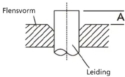
text_image
Flensvorm A Leidingnatural_image
Illustration of hands using a tool to lift a mechanical component (no text or symbols)VEREISTEN VOOR AANHAALMOMENTEN
| Buitendiameter van de leiding (mm) | Aanhaalmoment (N•m) Flensafmetingen (B) (mm) | Flensvorm |
| ∅ 6,35 (∅ 0,25") | 18~20 (180~200kgf.cm) 8,4~8,7 (0,33~0,34") | 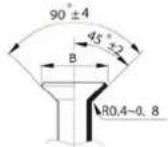 |
| ∅ 9,52 (∅ 0,375") | 32~39 (320~390kgf.cm) 13,2~13,5 (0,52~0,53") | |
| ∅ 12,7 (∅ 0,5") | 49~59 (490~590kgf.cm) 16,2~16,5 (0,64~0,65") | |
| ∅ 16 (∅ 0,63") | 57~71 (570~710kgf.cm) 19,2~19,7 (0,76~0,78") | |
| ∅ 19 (∅ 0,75") | 67~101 (670~1010kgf.cm) | 23,2~23,7 (0,91~0,93") |

GEBRUIK GEEN OVERMATIG AANHAALMOMENT
natural_image
Line drawing of hands using a tool to adjust or install a mechanical component (no text or symbols visible)LUCHT AFLATEN
natural_image
Technical line drawing of an air conditioner unit showing internal panel structure (no text or labels)text_image
Warning sign depicting a flame symbol in yellow and black on white backgroundAVISO:
natural_image
Simple line drawing of a garage with a patterned vent and handle (no text or symbols)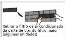
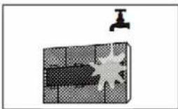
natural_image
Illustration of a faucet above a textured panel with a starburst pattern (no text or symbols)
CUIDADO
natural_image
Diagram of a grid with a label 'H' pointing to the top-right corner (no text or symbols on the grid itself)natural_image
Simple line drawing of a house with wavy lines indicating airflow or ventilation (no text or symbols)text_image
Warning symbol with crossed-out lightning bolt inside a circle, indicating no protection or hazard.natural_image
Simple line drawing of a device with a handle and internal components (no text or symbols)text_image
Safety warning sign showing no hazard and lightning symbol with hazard bandsnatural_image
Simple 3x3 grid diagram with a small triangular pointer on top-right corner (no text or symbols)natural_image
Prohibition sign with diagonal line crossing a shaded band and droplet symbols (no text)natural_image
Simple line drawing of a handheld device with a handle and control panel (no text or symbols)Voltar a colocar as pilhas
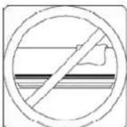
natural_image
Pure technical diagram of a mechanical component with no text, numbers, or symbolsnatural_image
Technical diagram of a mechanical device with mounting brackets and adjustment knobs (no text or symbols)natural_image
Diagram showing a pipe clamp securing a bolt, with motion arrows indicating movement (no text or symbols)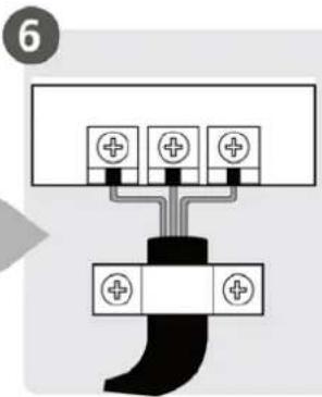
text_image
6natural_image
Illustration of hands holding a small object over a textured surface (no text or symbols)- Preparar a mangueira de escoamento
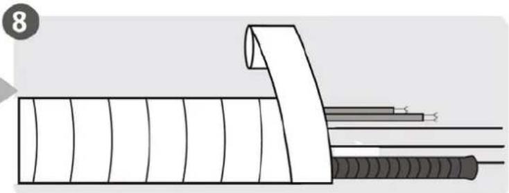
natural_image
Diagram of a cable being inserted into a wire, showing sheath and sheath cross-section (no text or symbols)natural_image
Illustration of two hands holding a rectangular object with horizontal lines and arrows indicating motion or force (no text or symbols)text_image
Diagram of an air conditioner system with numbered components including air conditioner, wall-mounted panel, and fan unit(1)
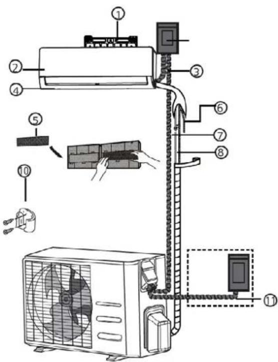
text_image
Diagram of an air conditioner system with numbered components and installation steps(2)
natural_image
Technical line drawing of a rectangular electronic component or enclosure with internal compartments (no text or symbols)text_image
Interior Parede Exterior 5-7mm (0.2-0.275in)DIMENSÕES DO PRATO DE MONTAGEM
natural_image
Technical line drawing of two rectangular electronic components with coiled leads and internal channels (no text or symbols)
CUIDADO
natural_image
Simple line drawing of a mechanical joint or bracket with a checkmark (no text or symbols)CORRETO
natural_image
Simple line drawing of a mechanical joint or bracket with a cross symbol (no text or labels)INCORRETO
natural_image
Diagram of a pipe connection with a wall and ground, no text or symbols presentINCORRECTO:
natural_image
Simple line drawing of a toilet or shower system with no text or symbolsINCORRETO:
natural_image
Hand holding a cylindrical object with a pointed tip, poised to write on a surface (no text or symbols visible)
ANTES DE REALIZAR QUAISQUER TRABALHOS ELÉTRICOS, LER OS SEGUINTES REGULAMENTOS
| Corrente nominal do aparelho (A) | Secção transversal nominal (mm2) |
| >3 and ≤ 6 0.75 | |
| >6 and ≤ 10 1 | |
| >10 and ≤ 16 1.5 | |
| >16 and ≤ 25 2.5 | |
| >25 and ≤ 32 4 | |
| >32 and ≤ 40 6 |
While crimping wires, make sure you dearly distinguish the Live ("L") Wire from other wires.

AVISO
text_image
Coperchio Vitenatural_image
Mechanical component diagram showing a flanged assembly with bolt holes and a central base (no text or symbols)Passo 2: Remover as rebarbas
natural_image
Illustration of a mechanical clamp or fixture with two plates and a handle (no text or symbols)PROLONGAMENTO DA TUBAGEM PARA ALÉM DA FORMA CÓNICA
| Diâmetro exterior do tubo (mm) | A (mm) | |
| Min. Max. | ||
| ∅ 6.35 (∅ 0.25") 0.7 (0.0275") 1.3 (0.05") | ||
| ∅ 9.52 (∅ 0.375") 1.0 (0.04") 1.6 (0.063") | ||
| ∅12.7 (∅ 0.5") 1.0 (0.04") 1.8 (0.07") | ||
| ∅ 16 (∅ 0.63") 2.0 (0.078") 2.2 (0.086") | ||
| ∅ 19 (∅ 0.75") 2.0 (0.078") 2.4 (0.094") | ||
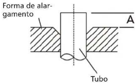
text_image
Forma de alargamento A Tubotext_image
Raio 10cm (4in)natural_image
Illustration of a hand using a tool to lift a bolt, no text or symbols presentnatural_image
Line drawing of hands using a tool to adjust or install a mechanical component (no text or symbols present)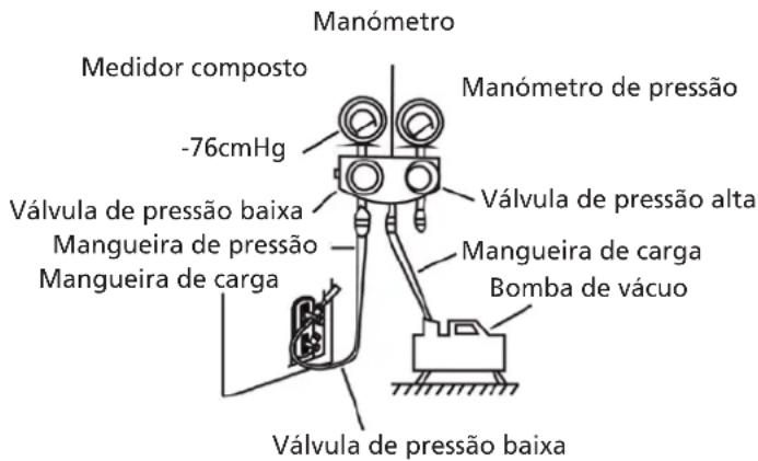
natural_image
Line drawing of an air conditioner unit with ventilation slots and a handle (no text or symbols)Distributed in Europe by PVG Holding B.V.
Benötigen Sie weitere Informationen oder treten Probleme auf, besuchen Sie bitte unsere Website www.qlima.com, oder setzen Sie sich mit unserem Kundendienst in Verbindung (T: +31 412 694 694).
For alle yderligere oplysninger eller ved eventuelle problemer med apparatet henvises til www.qlima.com eller det lokale Kundecenter (T: +45 77 34 33 30).
ES Si necesita información o si tiene algún problema, visite nuestra página Web www.qlima.es, o póngase en contacto con el servicio cliente (T: +34 916 113 113).
(F) Si vous souhaitez obtenir des informations supplémentaires ou si vous rencontrez un problème, rendez-vous sur notre site Web (www.qlima.fr / www.fr.qlima.be) ou contactez notre service client (T : +33 2 32 96 07 47 / +32 (0)3 326 39 39).
FHN Jos haluat huoltoapua, lisätietoja tai laitteen kanssa tulee ongelmia, tutustu verkkosivustoon osoitteessa www.qlima.com tai kysy neuvoa PVG kuluttajapalvelukeskuksesta (T: +45 77 34 33 30).
(68) If you need information or if you have a problem, please visit the our website (www.qlima.com) or contact our sales support (T: +31 412 694 694).
① Per informazioni e in caso di problemi, visitate il sito Web www.qlima.it oppure contattate il Centro Assistenza Clienti (T: +39 0571 628 500).
Hvis du trenger informasjon, eller hvis du har et problem med produktet, kan du gå til nettsidene www.qlima.com. Alternativt kan du kontakte med PVG' forbrukertjeneste (T: +45 77 34 33 30).
NL Als u informatie nodig hebt of als u een probleem hebt, bezoek dan de onze website (www.qlima.nl / www.qlima.be) of neem contact op met de afdeling sales support (T: +31 412 694 694 / +32 (0)3 326 39 39).
Se necessitar de informações ou se tiver problemas, visite o Web site www.qlima.es ou contacte o Centro de Assistência (T: +34 916 113 113).
W przypadku problemów i w celu uzyskania szczegółowych informacji odwiedź stronę internetową Qlima dostępną pod adresem www.qlima.com lub skontaktuj się z Centrum kontaktów Qlima (T: +48 48 613 00 70)
Om du behöver service eller information eller har problem med apparaten kan du besöka www.qlima.com eller kontakta Qlima kundtjänst (T: +45 77 34 33 30).
⑤u Če želite dodatne informacije, obiščite spletno mesto podjetja na naslovu www.qlima.si ali pokličite na telefonsko (T: +386 (0)41 674 139).