Conforto DC Lite - Fan SPC - Free user manual and instructions
Find the device manual for free Conforto DC Lite SPC in PDF.

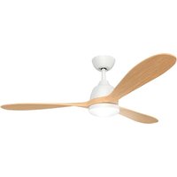
| Product Type | Ceiling Fan |
| Brand | SPC |
| Model | Conforto DC Lite |
| Category | Fan |
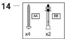
| Number of Blades | 4 |
| Minimum Installation Height | 2.3 m from floor |
| Minimum Distance to Obstacles | 1 m |
| Maximum Ceiling Bracket Weight | 30 kg |
| Power Supply | 220-240 V ~ 50 Hz |
| Motor Type | DC (direct current) |
| Number of Speeds | 6 |
| Operating Modes | Normal, Sleep, Nature, Breeze |
| Built-in Timer | 1h, 2h, 4h, 8h |
| Control | Remote control and SPC IoT app |
| LED Lighting | Integrated, with color temperature change (warm, neutral, cold) |
| Reversible Rotation Direction | Yes (summer/winter mode) |
| Breeze Function | Yes (speed lower than 1) |
| Cleaning | Soft non-linting cloth, without water or chemicals |
| Lubrication | None required |
| Included Parts | Ceiling bracket, remote control, receiver, balancing kit, extra long rod |
| Installation | By a qualified electrician |
Frequently Asked Questions - Conforto DC Lite SPC
User questions about Conforto DC Lite SPC
0 question about this device. Answer the ones you know or ask your own.
Ask a new question about this device
Download the instructions for your Fan in PDF format for free! Find your manual Conforto DC Lite - SPC and take your electronic device back in hand. On this page are published all the documents necessary for the use of your device. Conforto DC Lite by SPC.
USER MANUAL Conforto DC Lite SPC
natural_image
Row of white line drawings of different tools and fixtures on a blue background (no text or symbols)natural_image
Five white line drawings of different tools and fixtures on a blue background: screwdriver, wrench, electric shaver, ladder, and switch (no text or symbols)natural_image
Simple line drawing of a structural support frame with two vertical posts and two base supports (no text or symbols)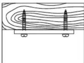
natural_image
Diagram showing two vertical cylindrical objects on a horizontal platform with contour lines above (no text or symbols)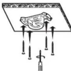
natural_image
Line drawing of a mechanical component with a rotating knob and base, showing no text or symbolsnatural_image
Diagram of a propeller with three blades and a circular base, showing mechanical assembly (no text or symbols)natural_image
Technical diagram showing mechanical assembly with a bolt and housing, including a magnified view of the internal components (no text or labels)natural_image
Pure mechanical assembly diagram showing a bracket and mounting base without any text or symbolsnatural_image
Diagram of a propeller with rotating components and directional arrows indicating rotation (no text or symbols)CONTROL DEL VENTILADOR
VINCULAR CON APP SPC IOT


natural_image
Pure mechanical component diagram without any text, numbers, or symbolsnatural_image
Simple line drawing of a cylindrical device with wires and connectors, no text or symbols presentnatural_image
Technical diagram showing mechanical assembly with two views: top view with a cylindrical component and arrow indicating direction, bottom view with a bearing housing (no text or symbols)natural_image
Line drawing of hands holding a mechanical component with an arrow indicating direction (no text or symbols)natural_image
Simple line drawing of a laboratory setup with a funnel, beaker, and tool (no text or labels)natural_image
Illustration of hands performing a mechanical tool manipulation (no text or symbols)natural_image
Line drawing of hands holding a mechanical component with an arrow indicating rotation (no text or symbols)natural_image
Technical diagram showing mechanical assembly with a bolted component and a close-up of a bearing housing (no text or symbols)natural_image
Diagram of a cylindrical device with connectors and wiring, showing two input/output ports and directional arrows (no text or symbols)natural_image
Pure mechanical assembly diagram showing a bracket and mounting base without any text or symbolsnatural_image
Diagram showing two water circulation patterns with sun, wind, and snow symbols (no text or labels)natural_image
Simple line drawing of a ceiling-mounted fan with a central hub and curved base, no text or symbols present.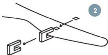
natural_image
Pure mechanical diagram showing a bracket and mounting detail without any text or symbolsMANTENIMIENTO Y LIMPIEZA.
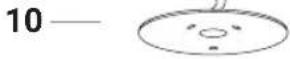
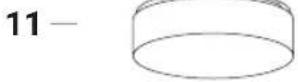
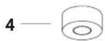
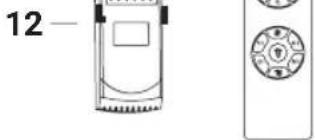
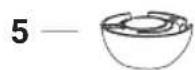
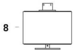
- Ceiling bracket
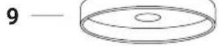
- Medallion
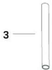
- Down rod
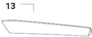
- Trim
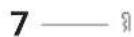
- Attachment
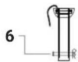
- Bolt
- Hook R
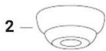
- Motor
- Bottom cover
- LED lamp
- Tulipa
- Remote receiver
- Blades
- Bag of screws and plugs
- Balancing kit

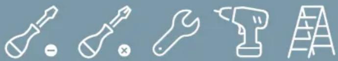
REQUIRED TOOLS

natural_image
Five white line-art icons on a blue background: screwdriver, wrench, screwdriver with hammer, power tool, and ladder (no text or symbols)SAFETY PRECAUTIONS
EN

Follow these instructions to ensure safe installation and proper operation of this equipment.

The electrical installation must be carried out by a qualified person.

This appliance is not a toy. Cleaning and maintenance to be carried out by the user should not be carried out by children without supervision.
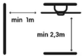
The fan must be installed in such a way that the blades are more than 2.3m from the ground. Make sure there is a space of at least 1m from where the fan is installed to any wall or other obstacle that its blades might collide with. The greater the distance, the more efficient the flow of air produced.
It is recommended to read the following instructions to ensure your safety:
-
The electrical installation must be carried out by someone qualified in accordance with the regulations in force in the country of installation.
-
Any action on the device's electrical connection, as well as its cleaning, must only be carried out after ensuring that the power supply is disconnected, by removing the corresponding protective switch of the installation to guarantee total isolation from the electrical supply.
-
You must ensure that the mounting bracket is fixed to a ceiling structure that is capable of supporting no less than 30 kg through the supplied screws. You need to make sure that the screws are screwed in along their full length. If mounting over a ceiling junction box, you must secure the fan bracket sufficiently to prevent it from loosening or twisting.
-
The earth cable of the fan must be connected to the earth network of the installation, to avoid any risk to people.
-
Do not connect the power supply of the fan motor to any regulation component or lighting switch, as this will cause the fan to malfunction and/or damage its motor. For the electrical connection, it is necessary to incorporate a isolator switch in accordance with the installation regulations, which ensures multi-pole cut-off, directly connected to the power terminals and must have a contact separation on all its poles, which provides total disconnection under conditions of overvoltage category III. Only use the fan controller to start or stop the fan.
-
It is recommended not to simultaneously use this type of fan in the same room as gas installations.
-
The fan must be stopped and have stopped rotating completely before reversing its direction of rotation. This will prevent damage to your motor and the control unit if applicable.
-
Do not insert anything that could hit the fan blades while it is rotating, as it could cause injury to people, damage the blades, and cause the unit to become unbalanced causing vibrations and wobble.
-
After mounting the fan, make sure all fixings are secure and tight to avoid any noise caused by loose items.
-
Due to the movement of the fan, some fasteners may loosen. Check all fasteners at least twice a year to make sure they are properly tightened. If necessary, they must be tightened again.
- If the power cord is damaged, it must be replaced by the manufacturer, its after-sales service or similar qualified personnel, in order to avoid danger.
- The light fitting should only be replaced by an original supplied by the manufacturer.
INSTALLATION
Note: This product should only be installed by licensed electricians.
Take out all of the components. Place the motor on a cloth or soft surface to avoid damaging its finish.
Handle the assembly carefully to avoid bending or scratching its case.
The fan should be assembled on the floor or on a table large enough so that no components fall.
Do not lift or carry the fan by the cables.
REQUIRED TOOLS
natural_image
Five white line-art icons on a solid gray background: screwdriver, wrench, power tool, ladder, and switch (no text or symbols)Ceiling bracket installation:
Mount the fan bracket onto the ceiling, in accordance with the minimum distance of 2.3m high and ensuring there are no obstacles within the radius of 1m around the fan itself.
Taking into account the length of the blades, install the ceiling mount at a minimum distance of:
1,70m aprox. for Conforto DC Nature and Conforto DC Max 2; 1,60m aprox. for Conforto DC Lite 2.
For solid ceilings For wooden ceilings
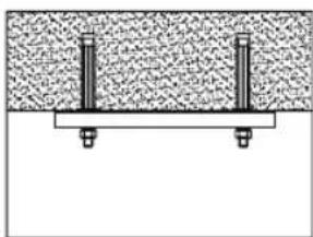
natural_image
Simple line drawing of a structural support with two vertical posts and a base plate (no text or symbols)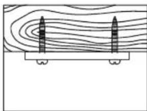
natural_image
Diagram showing two vertical cylindrical objects placed on a platform with contour lines above (no text or symbols)
Warning: Use the appropriate studs for the type of ceiling in which you will install the fan, taking into account its weight.
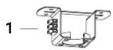
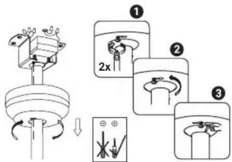
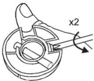
- Insert the screws which hold the fan blades. Use the guide stickers to identify the pairs of holes. Do not tighten the screws fully. Insert them all and screw them in together to ensure the blades are uniform.
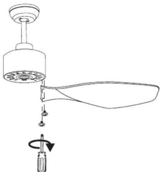
natural_image
Line drawing of a mechanical component with a rotating knob and base, showing no text or symbols- Place the cover on the underside of the fan using the 3 screws and pass the two cables through the central opening. Two screws will already be in place, line up the holes in the cover with their heads and once through, rotate the cover so they go through their guides. Next, insert the third screw from the bag of screws.
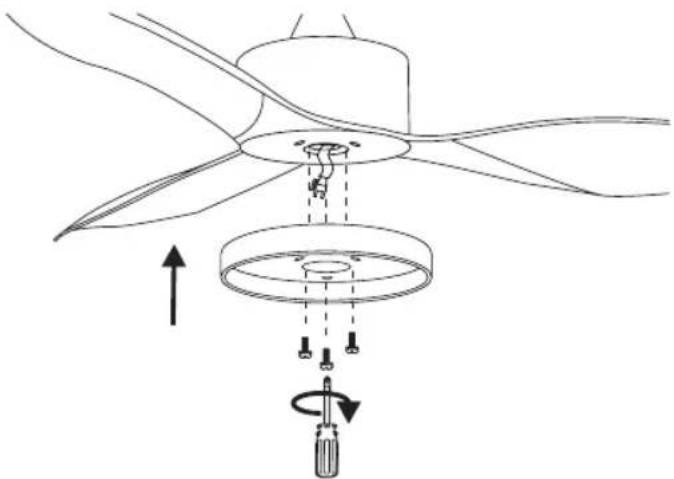
natural_image
Diagram of a propeller with three blades and a circular base, showing mechanical assembly (no text or symbols)- Connect the cable of the LED lamp with the cable that hangs at the bottom of the fan and insert the LED lamp with the magnets.
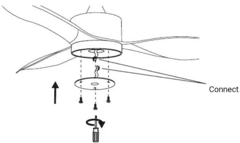
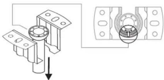
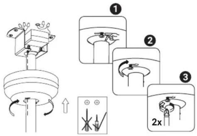
- Hang the fan supporting the attachment on the ceiling bracket.
natural_image
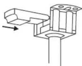
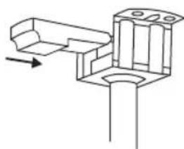
Technical diagram showing mechanical assembly with a bolt and housing, including a magnified view of the internal components (no text or labels)- Insert the remote bolt into the ceiling bracket.

natural_image
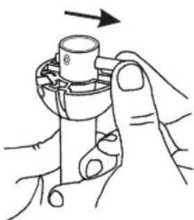
Pure mechanical assembly diagram showing a bracket and mounting base without any text or symbols- Connect the cables which come out of the down rod and the connection strip located on the remote bolt bracket. Proceed to connect the cables which hang from the ceiling at the connection opening (ensure that the circuit breaker has been lowered and that you follow the cable colours).
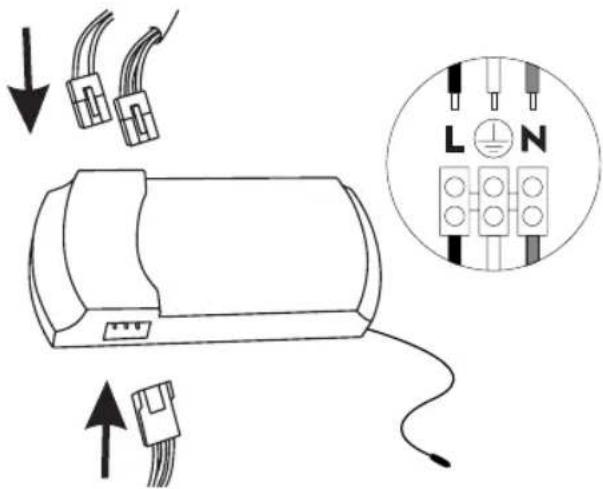
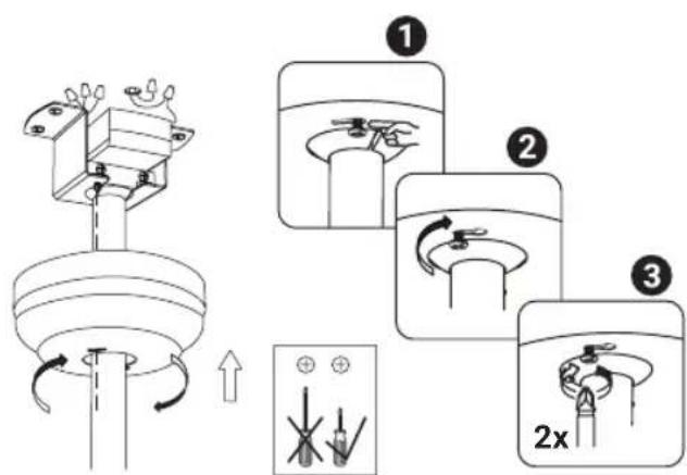
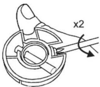
- Loosen the screws on the ceiling bracket so you can pass their heads through the holes on the ceiling rose. Once past, you can rotate the rosette so the screws go through the rail. When it has reached the end of its travel, tighten the screws so that the rosette does not move.
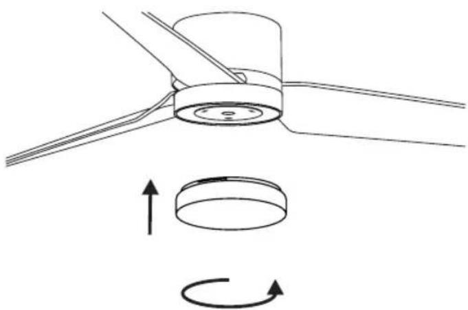
- Attach the lamp cover by turning it clockwise. In the case of the Lite 2 model, remove the protective film from the shade and insert it into position. Bend it slightly to fit better.
EN
natural_image
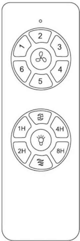
Diagram of a mechanical component with rotational motion arrows, no text or symbols presentFAN CONTROL
You can control your fan through your remote control or through the control panel of your SPC IoT application.

Change direction of rotation

Turn off fan
1 Speed 1
2 Speed 2
3 Speed 3
4 Speed 4
5 Speed 5
6 Speed 6
1h Programming 1h
2h Programming 2h
4h Programming 4h
8h Programming 8h

Turn on/off LED

Natural
LINK WITH SPC IOT APP
Once connected to the mains and prior to selecting synchronisation mode, check that the fan works by using the remote control.
- Download the SPC IoT APP- Install - Create account / Login.


- Create your family and the rooms in your house.
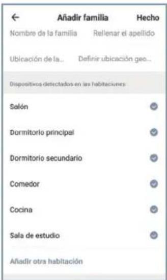
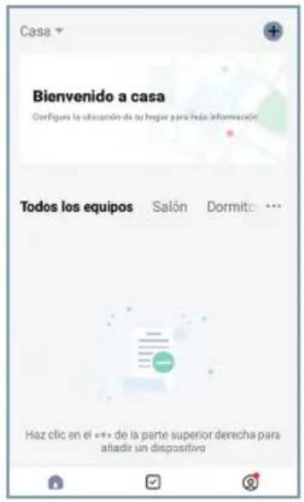
Turn on the Bluetooth, the location and the WiFi of the mobile device with which you are going to make the link. Make sure that theIoT device to which you are going to connect is switched on before clicking on the "+" symbol in the upper right part of the main page of the app (img. 1, img. 2).
Then, at the top of the page "Add device" the message "Discovering devices" will appear. If the device you want to link appears, press the "Add" button.
If more than one device is detected, click on the "+" button next to the devices you want to add. Once the process is finished, a √" will appear next to
the device name. Click on the "Next" button at the bottom to finish the link.
EN
When finished, you will see a window in which it says "Successfully added" over the icon and the name of the added device. Press "Done" at the top right to return to the main screen (img. 3, img. 4, img 5).
img. 1
Tap the "+" icon in the top right corner. Select your model within the "Fans" family. Tap on the top right corner again to switch from "Bluetooth" to "EZ Mode".
Turn on the equipment and in the first 5 seconds that it is turned on, press and hold the "FAN OFF" button on the remote for 5 seconds.
Enter your home's Wi-Fi 2.4Ghz network (5Ghz networks not supported) a progress indicator with a percentage will be shown, when it reaches 100% the device will have been successfully added.
SPC IOT APP
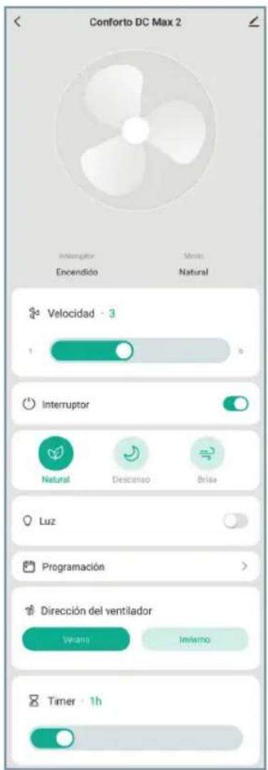
From the SPC IoT application, you can access the different controls your fan has available:
- Speed: Slide the horizontal control to change the fan speed.
- Switch: Turn the fan on or off.
- Modes:
Normal - Adjust the speed with the horizontal slider.
Sleep - Keep noise to a minimum so it doesn't bother you while you sleep.
Natural - the fan will change power to give you a feeling of natural breeze.
Breeze – The fan will run at speed less than 1.
- Light: Turn your fan light on or off.
- Programming: ProgrammingCreate routines to perform settings at selected times and days.
- Fan direction:
Summer mode - Generates a downdraft to cool you down.
Winter mode - it draws in cold air from the ground so that the heat from the ceiling lowers.
- Timer: Schedule fan switch off.
If it is necessary to separate the fan from the ceiling more than is possible with the standard stem, a longer stem is available in the box. The stem post is approximately 12cm longer than the standard one.
To change the stem you have to follow these steps:
First of all, remove the tulip and place a cloth on a large surface so as not to damage the fan when lowering it.
- Loosen the screws holding the canopy to the ceiling so you can rotate it out.
-
We recommend lowering the circuit breakers of the electrical panel since you will have to place your hands near the 220V connections.
-
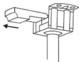
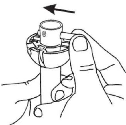
Pull the controller out of the ceiling mount hole.
natural_image
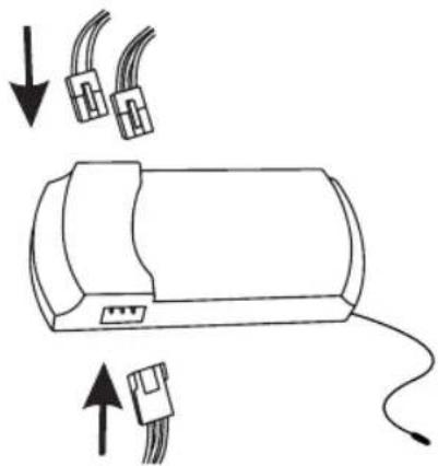
Pure mechanical component diagram without any text, numbers, or symbols- Disconnect the cables going from the fan to the controller.
natural_image
Simple line drawing of a cylindrical device with wires and connectors, no text or symbols present- Take down the fan and place it on the surface you have prepared.
natural_image
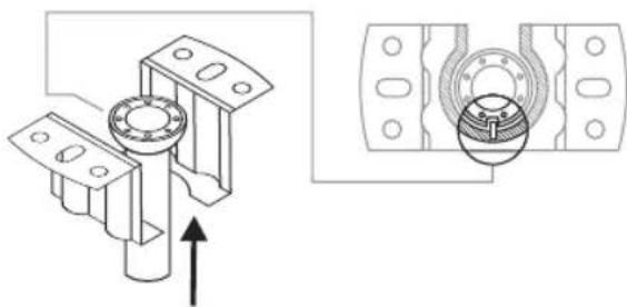
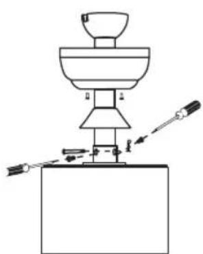
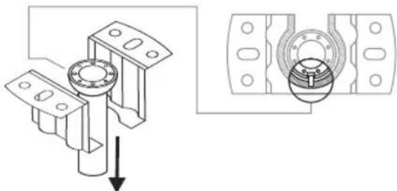
Technical diagram showing mechanical assembly with two views: top view with a cylindrical component and arrow indicating direction, bottom view with a bearing housing (no text or symbols)- Loosen the bolts that hold the mount to the stem from the top.
- Remove the pin to release the coupler. You can now remove the coupling, the rosette and the trim.
natural_image
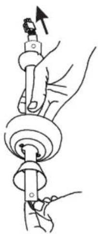
Line drawing of hands holding a mechanical component with an arrow indicating direction (no text or symbols)- Loosen the bolts that were under the trim, these hold the stem to the motor. Remove the R pin and pin to release the stem from the lower part.
natural_image
Simple line drawing of a laboratory setup with a funnel, beaker, and tool (no text or symbols)You can now remove the standard stem. Once the standard stem has been removed, the steps to mount the long stem are the same.
EN
First, run the motor cables through the bottom of the stem. The top has a screw thread in addition to the two pin holes. The lower one, only the pin holes. In other words, the upper part has 3 holes and the lower part only two.
When you put it in position, remember to insert the trim, the rosette and the coupler before putting the upper pin.
- Assemble the stem in this way, remember to put the type R hook to the lower pin so that it does not come out and tighten the screws so that the stem is attached correctly to the motor. Don't forget to run the cables all the way through the stem.
natural_image
Illustration of hands using a tool to adjust a mechanical component (no text or symbols present)- Place the remaining pin at the top of the stem.
natural_image
Line drawing of hands holding a mechanical component with an arrow indicating rotation (no text or symbols)- Raise the coupling so that both the indentations with the pin and the through bolt hole match up. Tighten the bolts that hold the mount to the stem.
- Hang the fan from the ceiling bracket.
natural_image
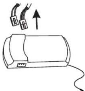
Technical diagram showing mechanical assembly with a bolt and housing, including a magnified view of the internal components (no text or labels)- Connect the fan cables to the controller.
natural_image
Diagram of a cylindrical device with two connectors and an attached cable, showing directional arrows (no text or symbols)- Slide the controller into its hole in the ceiling mount.
natural_image
Pure mechanical assembly diagram showing a bracket with mounting holes and a directional arrow (no text or symbols)- Screw the canopy back onto the ceiling bracket.
EN
And finally, if you removed the lampshade, put it back. You can now reconnect the electricity.
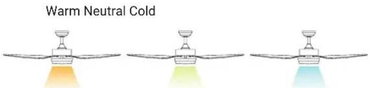
CHANGE IN COLOUR TEMPERATURE OF LIGHT
You can change the colour temperature of the light, using the remote or using the SPC IoT application from your terminal.
You just have to turn off the light and turn it on again for it to change:
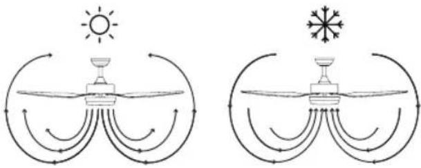
ROTATION DIRECTION. WINTER/SUMMER OPTION
The remote control switch controls direction, clockwise and anti-clockwise.
Summer option - The downdraft air stream creates a cooling effect as shown in the illustration.
Winter option - An updraft draws hot air away from the fan area as shown in the illustration. This allows the heating to be adjusted to a lower level.
Note: Turn off the fan and wait for it to come to a complete stop before changing the direction of the blades.
natural_image
Diagram illustrating solar radiation and wind patterns around a central water body, with no text or symbols present.RECODING THE REMOTE CONTROL WITH RECEIVER UNIT
- Connect the power (wall switch) of the fan you want to control, and then, within the next 10 seconds, press and hold the "LIGHT" key on the remote control for 5 seconds.
- A beep indicates that the connection has been completed and the equipment can function normally.
- The remote control and the receiver of the fan will have been synchronised. Turn off the fan using the wall switch and turn it back on, this step completes the syncing process.
Note: A single remote control can control several units of the same fan model. The remote is specific to your fan model.
BALANCING - BALANCE PROBLEMS IN FAN OPERATION
The swaying of the fan body during operation is not a symptom of malfunction (even reaching a couple of centimetres). To reduce sway, you can, with the fan switched off:
- Check the distance of each blade from the ceiling. Measurement from the ceiling can be done as the following picture shows.
- Check that the fixing of all the blades is correct by tightening all screws.
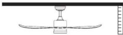
natural_image
Simple line drawing of a ceiling-mounted air conditioner unit with a curved base and top fixture (no text or symbols)If after the previous steps the balance issue has not been resolved, it is necessary to apply dynamic balancing, with the supplied kit, as explained below:
EN
-
Run the fan on the highest speed to create the most rocking.
-
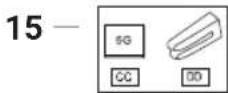
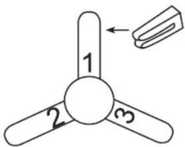
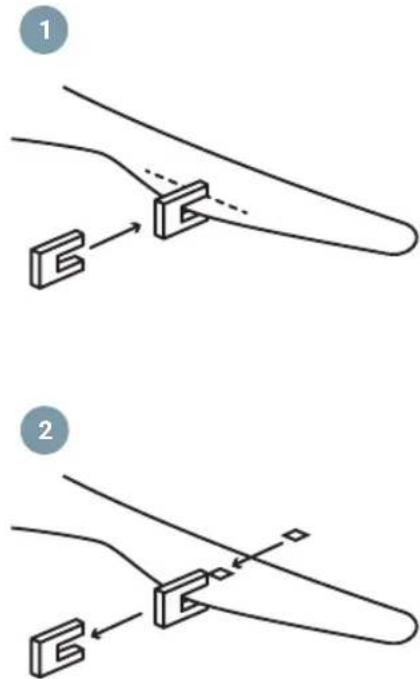
Turn off the fan. Select a blade and place the clip (see figure) on it, midway between the bracket and the edge of the blade.
-
Turn on the fan, check if the rocking has worsened or improved. Turn it off again, and if it hasn't improved, put the clip on another blade. Repeat this process and determine which blade the swing improves on.
-
Leave the clip on the blade that produces the best result. Move the clip back or forth on the blade until you find the position that works best.
-
Next, remove the clip and place one of the weights on top on the centre line of the blade, at the height of the position where the clip was.
MAINTENANCE AND CLEANING
- The natural movement of the fan could cause some connections to loosen. Check the blade support connections, fasteners, and accessories twice a year. Make sure they are fastened.
- Clean the fan periodically to keep it in optimal condition. Use a cloth to clean the equipment, do not use benzene, alcohol or chemical solvents. Do not use abrasive or aerosol products. Do not use water to clean it, as it may damage the motor or cause electric shock.
- Use only a soft brush or lint-free cloth to avoid scratching the finish.
- It is not necessary to lubricate the fan.
Note: Failure to follow these instructions leads to the loss of the equipment warranty.
EN
LISTA DE PEÇAS
natural_image
Five white line-art icons on a solid gray background: screwdriver, wrench, screwdriver with hammer, ladder, and switch (no text or symbols)PRECAUÇÕES DE SEGURANÇA
PT

natural_image
Five white line drawings of different tools and fixtures on a blue background (no text or symbols)natural_image
Simple line drawing of a structural support with two vertical posts and a base plate (no text or symbols)
natural_image
Diagram showing two vertical cylindrical objects placed on a platform with contour lines above (no text or symbols)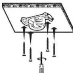
natural_image
Line drawing of a mechanical component with a rotating knob and base, showing no text or symbolsnatural_image
Diagram of a propeller with three blades and a circular base, showing mechanical assembly (no text or symbols)natural_image
Technical diagram showing mechanical assembly with a bolted component and a bearing housing (no text or symbols)- Introduza o recetor remoto no suporte do teto.
natural_image
Pure technical line drawing of a mechanical bracket or mounting structure without any text, numbers, or symbolsnatural_image
Diagram of a propeller with rotating components and directional arrows indicating rotation (no text or symbols)CONTROLO DO VENTILADOR
VINCULAR COM APP SPC IOT


natural_image
Pure mechanical assembly diagram showing a bracket and mounting base without any text or symbolsnatural_image
Simple line drawing of a cylindrical device with wires and connectors, no text or symbols presentnatural_image
Technical diagram showing mechanical assembly with mounting bracket and bearing housing (no text or symbols)natural_image
Line drawing of hands holding a mechanical component with an arrow indicating direction (no text or symbols)natural_image
Simple line drawing of a laboratory setup with a funnel, beaker, and tool (no text or symbols)natural_image
Illustration of hands using a tool to adjust a mechanical component (no text or symbols present)natural_image
Line drawing of hands holding a mechanical component with an arrow indicating rotation (no text or symbols)natural_image
Technical diagram showing mechanical assembly with a bolt and housing, including a magnified view of the bearing (no text or labels)natural_image
Diagram of a device with two connectors and an attached cable, showing directional arrows (no text or symbols)natural_image
Pure mechanical assembly diagram showing a bracket and mounting base without any text or symbolsnatural_image
Two identical diagrams showing sun, water, and snow structures with curved flow lines (no text or symbols)RECODIFICAÇÃO DO COMANDO À DISTÂNCIA COM UNIDADE RECETORA
natural_image
Simple line drawing of a ceiling-mounted air conditioner unit with a curved base and top fixture (no text or symbols)natural_image
Five white line-art icons on a blue background: screwdriver, wrench, screwdriver with hammer, power tool, and ladder (no text or symbols)PRÉCAUTIONS DE SÉCURITÉ
FR

natural_image
Five white line-art icons on a blue background: screwdriver, wrench, power tool, ladder, and lamp (no text or symbols)natural_image
Simple line drawing of a structural support with two vertical posts and a base plate (no text or symbols)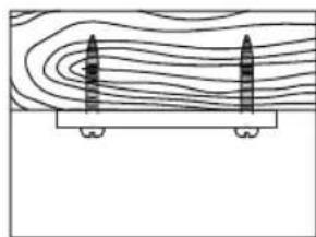
natural_image
Diagram showing two vertical structures above a horizontal platform with contour lines (no text or symbols)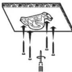
natural_image
Line drawing of a mechanical component with a rotating knob and base, showing no text or symbolsnatural_image
Diagram of a propeller with three blades and a circular base, showing mechanical assembly (no text or symbols)natural_image
Technical diagram showing mechanical assembly with a bolted component and a bearing housing (no text or symbols)natural_image
Pure mechanical assembly diagram showing a bracket and mounting base without any text or symbolsnatural_image
Technical diagram of a propeller with rotating base and rotation arrow (no text or symbols)CONTRÔLE DU VENTILATEUR


flowchart
graph TD
    A["Initial Setup"] --> B["2x Speed Measurement"]
    B --> C["Assembly"]
    C --> D["Final Assembly"]
natural_image
Pure mechanical assembly diagram showing a bracket and mounting base without any text or symbolsnatural_image
Simple line drawing of a cylindrical device with wires and connectors, no text or symbols presentnatural_image
Technical diagram showing mechanical assembly with two views: top view with a bolt and shaft, bottom view with a bearing housing (no text or symbols)natural_image
Line drawing of hands holding a mechanical component with an arrow indicating direction (no text or symbols)natural_image
Simple line drawing of a laboratory setup with a funnel, beaker, and tool (no text or symbols)natural_image
Illustration of hands using a tool to lift a mechanical component (no text or symbols)natural_image
Line drawing of hands holding a mechanical component with an arrow indicating rotation (no text or symbols)natural_image
Technical diagram showing a mechanical assembly with a bolt and housing, alongside its cross-sectional view (no text or labels)natural_image
Diagram of a cylindrical device with connectors and wiring, showing two input/output arrows (no text or symbols)natural_image
Pure mechanical assembly diagram showing a bracket and mounting base without any text or symbolsnatural_image
Diagram showing two water circulation patterns with sun, wind, and rain symbols (no text or labels)RECODAGE DE LA TÉLÉCOMMANDE AVEC LE RÉCEPTEUR
natural_image
Simple line drawing of a ceiling fan with a bulb and curved base (no text or symbols)ENTRETIEN ET NETTOYAGE

STRUMENTI NECESSARI
natural_image
Five white line-art icons on a gray background: a flask, a wrench, a tool, and a ladder (no text or symbols)natural_image
Five white line drawings of different tools and fixtures on a blue background: screwdriver, wrench, electric shaver, ladder, and switch (no text or symbols)natural_image
Simple line drawing of a structural support with two vertical posts and a base plate (no text or symbols)
natural_image
Diagram of two vertical structures on a platform with contour lines above, no text or symbols present
natural_image
Line drawing of a mechanical component with a rotating screwdriver and fan assembly (no text or symbols)natural_image
Diagram of a propeller with three blades and a circular base, showing mechanical assembly (no text or symbols)natural_image
Technical diagram showing mechanical assembly with a bolt and housing, including a magnified view of the internal components (no text or labels)natural_image
Pure mechanical assembly diagram showing a bracket and mounting base without any text or symbolsnatural_image
Diagram of a propeller with rotating components and directional arrows indicating rotation (no text or labels)CONTROLLO DEL VENTILATORE
VINCOLARE CON APP SPC IOT


natural_image
Pure mechanical assembly diagram showing a bracket and mounting base without any text or symbolsnatural_image
Simple line drawing of a cylindrical device with wires and connectors, no text or symbols presentnatural_image
Technical diagram showing mechanical assembly with two views: top view with a bolt and shaft, bottom view with a bearing housing (no text or symbols)natural_image
Line drawing of hands holding a mechanical component with an arrow indicating direction (no text or symbols)natural_image
Simple line drawing of a laboratory setup with a funnel, beaker, and tool (no text or symbols)natural_image
Illustration of hands using a tool to lift a mechanical component (no text or symbols)natural_image
Line drawing of hands holding a mechanical component with an arrow indicating rotation (no text or symbols)natural_image
Technical diagram showing a mechanical assembly with a cylindrical component and a bearing housing (no text or symbols present)natural_image
Diagram of a cylindrical device with connectors and wiring, showing two input/output arrows (no text or symbols)natural_image
Pure mechanical assembly diagram showing a bracket and mounting base without any text or symbolsnatural_image
Diagram showing two water circulation patterns with sun, wind, and ice (no text or labels)RICODIFICA DEL TELECOMANDO CON L'UNITÀ RICEVENTE
natural_image
Simple line drawing of a ceiling fan with a central hub and curved blades, no text or symbols present.EN: To see more details about the operation of this device or any other technical query, go to: support.spc.es