925 - Thermometer Testo - Free user manual and instructions
Find the device manual for free 925 Testo in PDF.

| Product type | Digital thermometer |
| Brand | Testo |
| Model | 925 |
| Measured quantities | Temperature (°C / °F) |
| Measuring range | -50.0 to +1000 °C / -58.0 to +1832.0 °F |
| Resolution | 0.1 °C / 0.1 °F (-50.0 to +199.9 °C / -58.0 to +391.8 °F) 1 °C / 1 °F (remainder of the range) |
| Accuracy (±1 digit) | ±0.5 °C + 0.3 % of measured value (-40 to +900 °C) ±0.7 °C + 0.5 % of measured value (remainder) |
| Probe type | Type K thermocouple (NiCr-Ni) with connector |
| Power supply | 1 battery or 9 V rechargeable battery |
| Battery life | Approx. 200 h (probe connected, backlight off) / 68 h (backlight on) Approx. 45 h (radio probe, backlight off) / 33 h (backlight on) |
| Display | Digital display with backlight |
| Main functions | Hold (value hold), Min/Max, threshold alarm, Auto Off, Auto Hold, infrared printing |
| Interfaces | Infrared (for printer), optional radio module (915 MHz / 869.85 MHz) |
| Protection | IP65 with TopSafe (accessory) |
| Operating temperature | -20 to +50 °C / -4 to +122 °F |
| Storage temperature | -40 to +70 °C / -40 to +158 °F |
| Cleaning and maintenance | Clean the housing with a damp cloth (soapy water). Do not use solvents or harsh cleaning agents. |
| Safety | Do not use in explosive atmospheres. Do not open the device for any operation not described. Observe the temperature limits of cables and connectors (70 °C max). |
| Warranty | 2 years |
| Available accessories | Radio module, radio probes, infrared printer, TopSafe, various TC probes |
Frequently Asked Questions - 925 Testo
User questions about 925 Testo
0 question about this device. Answer the ones you know or ask your own.
Ask a new question about this device
Download the instructions for your Thermometer in PDF format for free! Find your manual 925 - Testo and take your electronic device back in hand. On this page are published all the documents necessary for the use of your device. 925 by Testo.
USER MANUAL 925 Testo
Temperature measuring instrument
General notes ......22
-
Safety advice....23
-
Intended purpose .....24
-
Product description....25
3.1 Display and control elements .....25
3.2 Interfaces ......26
3.3 Voltage supply 26
-
Commissioning 27
-
Operation 28
5.1 Connect the probe....28
5.2 Switching the instrument on / off 28
5.3 Switching the display light on / off 29
5.4 Performing settings ....29
-
Measuring 34
-
Care and maintenance ....36
-
Questions and answers....37
-
Technical data ....38
-
Accessories / Spare parts 39
General notes
This chapter provides important advice on using this documentation.
The documentation contains information that must be applied if the product is to be used safely and efficiently.
Please read this documentation through carefully and familiarise yourself with the operation of the product before putting it to use. Keep this document to hand so that you can refer to it when necessary.
Identification
| Representation Meaning Comments | |
| i | Note Offers helpful tips and information. |
| ➢, 1, 2 Objective Denotes the objective that is to be achieved via the steps described. Where steps are numbered, you must always follow the order given! | |
| ✓ | Condition A condition that must be met if an action is to be carried out as described. |
| ➢, 1, 2, ... Step Carry out steps. Where steps are numbered, you must always follow the order given! | |
| Text Display text Text appears on the instrument display. | |
| Button | Control button Press the button. |
| - Result Denotes the result of a previous step. | |
| → | Cross-reference Refers to more extensive or detailed information. |
1. Safety advice
This chapter gives the general rules which must be followed and observed if the product is to be handled safely.

Avoid personal injury/damage to equipment
Do not use the instrument and probes to measure on or near live parts.
Never store the instrument/probes together with solvents and do not use any dessicants.
Product safety/preserving warranty claims
Operate the instrument only within the parameters specified in the Technical data.
Always use the instrument properly and for its intended purpose. Do not use force.
Do not expose handles and feed lines to temperatures in excess of 70 °C unless they are expressly permitted for higher temperatures.
Temperatures given on probes/sensors relate only to the measuring range of the sensors.
Open the instrument only when this is expressly described in the documentation for maintenance and repair purposes.
Carry out only the maintenance and repair work that is described in the documentation. Follow the prescribed steps when doing so. For safety reasons, use only original spare parts from Testo.
Ensure correct disposal
Take faulty rechargeable batteries/spent batteries to the collection points provided for them.
Send the product back to Testo at the end of its useful life. We will ensure that it is disposed of in an environmentally friendly manner.
Instruments with radio module 915.00MHz FSK
Warning: Changes or modifications not expressly approved by the party responsible for compliance could void the user's authority to operate the equipment.
This equipment has been tested and found to comply with the limits for a Class B digital device, pursuant to Part 15 of the FCC Rules.
These limits are designed to provide reasonable protection against harmful interference in a residential installation. This equipment generates, uses and can radiate radio frequency energy and, if not installed and used in accordance with the instructions, may cause harmful interference to radio communications.
However, there is no guarantee that interference will not occur in a particular installation. If this equipment does cause harmful interference to radio or television reception, which can be determined by turning the equipment off and on, the user is encouraged to try to correct the interference by one or more of the following measures:
- Reorient or relocate the receiving antenna.
- Increase the separation between the equipment and receiver.
- Connect the equipment into an outlet on a circuit different from that to which the receiver is needed.
- Consult the dealer or an experienced radio/TV technician for help.
Operation is subject to the following two conditions: - this device may not cause harmful interference, and
- this device must accept any interference received, including interference that may cause undesired operation.
2. Intended purpose
This chapter gives the areas of application for which the product is intended.
Use the product only for those applications for which it was designed. Ask Testo if you are in any doubt.
testo 925 is a compact measuring instrument for measuring temperatures.
The product was designed for the following tasks/applications:
- HVAC applications
- Measuring surface temperatures
The product should not be used in the following areas:
- Areas at risk of explosion
- Diagnostic measurements for medical purposes
3. Product description
This chapter provides an overview of the components of the product and their functions.

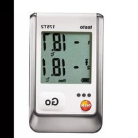
3.1 Display and control elements
Overview
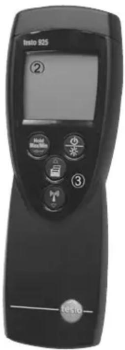
text_image
Info 925 ② Hold Max/Min ③ 3 y1 testo① Infrared interface, probe socket(s)
② Display
③ Control buttons
④ Radio module compartment, battery compartment (rear)
Key functions
 |
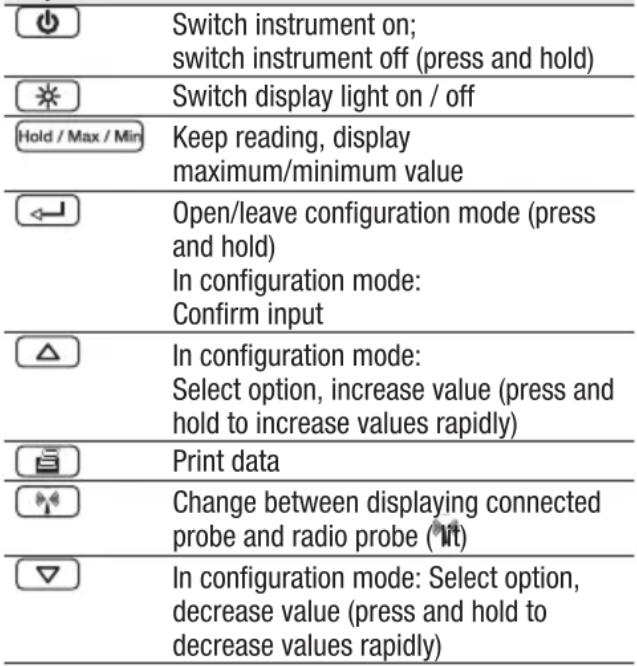 |
Important displays
| Display Meaning | |
| Battery capacity (bottom left in display):4 segments in the battery symbol are lit: Instrument battery is fully charged· No segments in the battery symbol are lit: Battery is almost spent | |
| Print function: Readings are sent to the printer | |
| Upper alarm limit: Lit if exceeded | |
| Lower alarm limit: Lit if undershot | |
| Measurement channel: Radio probe (the number of “radio wave” segments shown indicates the strength of the signal) | |
3.2 Interfaces
Infrared interface
Measurement data can be sent to a Testo printer via the infrared interface on the head of the instrument.
Sensor socket(s)
Plug-in measuring probes can be connected via the probe socket(s) on the head of the instrument.
Radio module (accessory part)
i Radio probes may only be used in countries in which they have been Type Approved (see application information of the radio probe).
A radio measuring probe can be connected via the radio module.
3.3 Voltage supply
Voltage is supplied by means of a 9 V monobloc battery (included in delivery) or rechargeable battery. It is not possible to run the instrument from the mains supply or charge a rechargeable battery in the instrument.
4. Commissioning
This chapter describes the steps required to commission the product.
en
➢ Removing the protective film on the display:
Pull the protective film off carefully.
➢ Inserting a battery/rechargeable battery:
1 To open the battery compartment on the rear of the instrument, push the lid of the battery compartment in the direction of the arrow and remove.
2 Insert a battery/rechargeable battery (9 V monobloc). Observe the polarity!
3 To close the battery compartment, replace the lid of the battery compartment and push it against the direction of the arrow.
- The instrument switches itself on and configuration mode is opened.
4 Set the date, time and unit of measurement.
→ See the chapter PERFORMING SETTINGS, objectives SETTING THE DATE/TIME and following.
➢ Inserting a radio module (accessory part):
i Radio probes may only be used in countries in which they have been Type Approved (see application information of the radio probe).
√ The instrument is switched off.
1 To open the radio module compartment on the rear of the instrument, push the clip lock downwards and remove the lid of the radio module compartment.
2 Insert the radio module.
3 To close the radio module compartment, replace the radio module compartment and close it.
5. Operation
This chapter describes the steps that have to be executed frequently when using the product.
5.1 Connect the probe
Plug-in probes
Plug-in probes must be connected before the measuring instrument is switched on so that they are recognised by the instrument.
Insert the connector of the probe into the probe socket.
Radio probes
i Radio probes may only be used in countries in which they have been Type Approved (see application information of the radio probe).
A radio module (accessory part) is required for the use of radio probes. The radio module must be connected before the measuring instrument is switched on so that it is recognised by the instrument.
Each radio probe has a probe ID (identification number). This must be set in configuration mode.
→ See the chapter PERFORMING SETTINGS.
5.2 Switching the instrument on / off
▶ Switching the instrument on:
Press ⏻ .
- Measurement view is opened: The current reading is displayed, or ---- lights up if no reading is available.
▶ Switching the instrument off:
Press and hold (for approx. 2s) until the display goes out
en
5.3 Switching the display light on / off
▶ Switching the display light on / off:
√ The instrument is switched on.
Press※.
5.4 Performing settings
1 To open configuration mode:
√ The instrument is switched on and is in measurement view. Hold, Max or Min are not activated.
Press and hold (for approx. 2s) until the display changes.
You can change to the next function with 📄 You can leave configuration mode at any time. To do so, press and hold (for approx. 2s) until the instrument has changed to measurement view. Any changes that have already been made in configuration mode will be saved.
2 To set the alarm function:
√ Configuration mode is opened, Alarm is displayed.
1 Select the desired option with and confirm with
- 0FF: Switches the alarm function off.
- On: Switches the alarm function on.
OFF was selected:
Continue with objective TO REGISTER THE RADIO PROBE.
On was selected:
2 Use /to set the value for the upper alarm threshold ( 1 and confirm with .
3 Use /to set the value for the lower alarm threshold (↓ and confirm with .
3 To register the radio probe:
i Radio probes may only be used in countries in which they have been Type Approved (see application information of the radio probe).
The setting function for radio probes is only available if a radio module (accessory part) is inserted into the measuring instrument.
→ See the chapter COMMISSIONING.
If no radio module is inserted:
→ Continue with objective To SET AUTO OFF.
Each radio probe has a probe ID (RF ID). This consists of the last 3 digits of the serial no. and the position of the slide switch in the radio probe (H or L).
√ Configuration mode is opened and RF ID and Auto are lit.
√ The radio probe is switched on.
1 Select the desired option with and confirm with ←:
- YES: Switches automatic probe detection on (recommended).
- no: Switches automatic probe detection off.
no was selected:
2 Use /to set the probe ID manually and confirm with
YES was selected:
- Automatic probe detection is started. Auto flashes while the instrument looks for a radio probe that is switched on.
- Once a radio probe is found, the probe ID is displayed. If no probe is found, NONE lights up.
Possible reasons why probes are not found:
- The radio probe is not switched on or the battery of the radio probe is spent.
- The radio probe is outside the range of the measuring instrument.
- Sources of interference are influencing the radio transmission (e.g. reinforced concrete, metal objects, walls or other barriers between transmitter and receiver, other transmitters of the same frequency, strong electromagnetic fields).
If necessary, rectify the possible causes for the disruption to the radio transmission and start automatic probe detection again with △
- If further wireless probes are within reception range, the probe ID of a different wireless probe may be displayed.
If necessary: switch off other wireless probes or remove from the reception range, and start automatic probe detection again with △
2 Press to change to the next function.
4 To set Auto Off:
√ Configuration mode is opened, Auto Off is lit.
Select the desired option with and confirm with
- On: The measuring instrument switches off automatically if no button is pressed for 10 min. Exception: A recorded reading is shown on the display (Hold or Auto Hold is lit).
- OFF: The measuring instrument does not switch itself off automatically.
5 To set Auto Hold:
The Auto Hold function is only active on plug-in measuring probes.
√ Configuration mode is opened, Auto Hold is lit.
1 Select the desired option (5, 10, 15, 20s) with △ and confirm with ⚠
- OFF: Readings are not recorded automatically.
- On: Once a stable reading is obtained (change in reading < 0.2^ / 0.4^ in the set evaluation time), it is recorded automatically.
OFF was selected:
→ Continue with objective To SET THE MAX./MIN. PRINT FUNCTION.
On was selected:
2 Use ☐ to set the value for the evaluation time (in s) and confirm with ☐
6 To set the max./min.print function:
√ Configuration mode is opened, MaxMin and are lit.
Select the desired option with and confirm with
- On: Maximum and minimum values are printed out as well when current or recorded readings are printed.
- OFF: Maximum and minimum values are not printed out as well when current or recorded readings are printed.
7 To set the date/time:
√ Configuration mode is opened, Year is lit.
1 Use ☐ to set the current year and confirm with ⏻.
2 Use /to set the other values for the month (Month), day (Day) and time (Time) and confirm each one with
8 To set the unit of measurement:
√ Configuration mode is opened, °C or °F flashes.
Select the desired unit of measurement with and confirm with
9 To reset:
√ Configuration mode is opened, RESET is lit.
Select the desired option with and confirm with
- no: Instrument is not reset.
- Yes: Instrument is reset. The instrument is reset to the factory settings. The setting of the probe ID for the radio probe is not reset.
- The instrument returns to measurement view.
6. Measuring
This chapter describes the steps that are required to perform measurements with the product.
√ The instrument is switched on and is in measurement view.
▶ Taking a measurement:
Put the probe in position and read off the readings.
With the Auto Hold function on:
The Auto Hold function is only active on plug-in measuring probes.
- Auto Hold flashes during measurement.
- If the reading is stable within the set evaluation time, a signal tone is given and the reading is recorded.
Start measurement again with
With the alarm function on and if the alarm threshold is exceeded or not undershot:
- Alarm lights up and a signal tone is given.
- The alarm goes out if the reading goes below the upper or above the lower threshold again.
➢ Changing the measurement channel display:
You can change between displaying plugged-in probes and radio probes (✗).
To change the display: Press
Holding the reading, displaying the maximum/minimum value:
The current reading can be recorded. The maximum and minimum values (since the instrument was last switched on) can be displayed.
Press to several times until the desired value is displayed.
- The following are displayed in turn:
- Max: Maximum value
- Min: Minimum value
- The current reading
- Hold: the recorded reading
- In addition to the recorded, maximum or minimum readings, the 2nd reading line shows the current reading
➢ Resetting the maximum/minimum values:
The maximum/minimum values of all channels can be reset to the current reading.
This function is not available if the Auto Hold function is switched on.
1 Press Hold / Max / Min several times until Max or Min lights up.
2 Press and hold Hold / Max / Min
- The displayed value flashes twice. All maximum and minimum values are reset to the current reading
▶ Printing rheadings:
The readings shown on the display (current reading, recorded reading or max./min. reading) can be printed out.
A Testo printer is required (accessory part).
With the Max./Min. print function switched on, the maximum and minimum values are printed out as well as the current reading or recorded reading.
→ See the chapter PERFORMING SETTINGS.
1 Configure the instrument so that the value to be printed is shown on the display.
2 Press
7. Care and maintenance
This chapter describes the steps that help to maintain the functionality of the product and extend its service life.
▶ Cleaning the housing:
Clean the housing with a moist cloth (soap suds) if it is dirty. Do not use aggressive cleaning agents or solvents!
➢ Changing the battery/rechargeable battery:
√ The instrument is switched off.
1 To open the battery compartment on the rear of the instrument, push the lid of the compartment in the direction of the arrow and remove it.
2 Remove the spent battery/rechargeable battery and insert a new battery/rechargeable battery (9 V monobloc). Observe the polarity!
3 To close the battery compartment, replace the lid of the compartment in position and push it against the direction of the arrow.
If the voltage supply had been interrupted for a long period, the date/time and unit of measurement will have to be reset:
- The instrument switches itself on and configuration mode is opened.
Set the date/time and unit of measurement.
See the chapter PERFORMING SETTINGS, objectives SETTING THE DATE/TIME and following.
8. Questions and answers
en
This chapter gives answers to frequently asked questions.
| Question Possible causes Possible solution | ||
| is lit (bottom left · Instrument battery is · Replace instrument in display). almost spent. battery.is lit (above · Radio probe battery · Replace radio probe symbol). is almost spent. battery. | ||
| Instrument switches · Auto Off function Switch function off.itself off. is switched on. | ||
| · Residual capacity of battery is too low. | · Replace battery | |
| Display: ---- | · Sensor is not plugged in. | · Switch instrument off, connect probe and switch instrument back on again. |
| · Sensor break. · Please contact your dealer or Testo Customer Service. | ||
| Display: uuuu | · Permitted measuring range was undershot. | · Keep to permitted measuring range. |
| Display: 0000· | Permitted measuring range was exceeded. | · Keep to permitted measuring range. |
| Display: no Signal | · Registered probe was not found. | · Switch on probe.· Bring probe into reception range.· Register radio probe again, see chapter PERFORMING SETTINGS, objective TO REGISTER THE RADIO PROBE. |
| Date/time are no longer correct | · Voltage supply was interrupted for a longer time | · Reset date and time. |
If we are unable to answer your question, please contact your dealer or Testo Customer Service. Contact details can be found on the guarantee card or on the Internet under www.testo.com.
9. Technical data
| Characteristic Value | |
| Parameters Temperature (°C/°F) | |
| Meas. range -50.0...+1000°C / -58.0...+1832.0°F | |
| Resolution 0.1°C / 0.1°F (-50.0...+199.9°C / -58.0...+391.8°F)1°C / 1°F (rest of range) | |
| Accuracy (±0.5°C+0.3% of reading) / (±0.9°F+0.3% of reading)(±1 Digit) (-40.0...+900°C / -40.0...+1652°F)(±0.7°C+0.5% of reading) / (±1.3°F+0.5% of reading)(rest of range) | |
| Sensor connections 1x Omega TC socket for temperature probetype K (NiCr-Ni), radio module (accessory part) | |
| Measuring rate 2/s | |
| Operating temperature range -20 ... +50°C / -4 ... +122°F | |
| Storage temperature -40 ... +70°C / -40 ... +158°F | |
| Voltage supply 1x 9 V monobloc battery/rech. battery | |
| Running time (display with probe connected: approx. 200h / approx. 68h, lighting off / on) | with radio probe: approx. 45h / 33h |
| Protection class | with TopSafe (accessory part) and probe connected: IP65 |
| EC Directive | 89/336/EEC |
| Warranty | 2 years |
10. Accessories / Spare parts
en
| Name Part no. | |
| Radio modules1 | |
| Radio module 869.85MHz, authorisation for e. g. DE, ES, IT, FR, GB | 0554 0188 |
| Radio module 915.00MHz, authorisation for e. g. USA 0554 0190 | |
| Radio probes1 | |
| Radio immersion/penetration probe, NTC, authorisation for e. g. DE, ES, IT, FR, GB | 0613 1001 |
| Radio immersion/penetration probe, NTC, authorisation for e. g. USA 0613 1002 | |
| Universal radio handles | |
| Radio handle for plug-in probeheads incl. TC adapter, authorisation for e. g. DE, ES, IT, FR, GB | 0554 0189 |
| Radio handle for plug-in probeheads incl. TC adapter, authorisation for e. g. USA 0554 0191 | |
| Adapter for connection to TC probes on radio handle 0554 0222 | |
| TC -probehead for air/immersion tip, attachable to radio handle 0602 0293 | |
| TC probes, type K | |
| Water-proof immersion/penetration probe, TC type K 0602 1293 | |
| Water-proof surface probe with widened measurement tip for smooth surfaces, TC type K 0602 1993 | |
| Robust air probe, TC type K 0602 1793 | |
| Miscellaneous | |
| TopSafe testo 925, protects from impact and dirt particles 0516 0221 | |
| Testo printer with IRDA and infrared interface, 1 roll thermal paper and 4 round cell batteries 0554 0547 | |
^1 Radio probes may only be used in countries in which they have been Type Approved (see application information of the radio probe).
For a complete list of all accessories and spare parts, please refer to the product catalogues and brochures or look up the www.testo.com Internet site.
Notes40
testo 925