MS1190M - Sewing machine JUKI - Free user manual and instructions
Find the device manual for free MS1190M JUKI in PDF.



| Product Type | Industrial sewing machine |
| Brand | Juki |
| Model | MS1190M (variants V045 and V046) |
| Application | For medium fabrics (MS1190M/V045 and MS1190M/V046) |
| Number of needles | 2 |
| Maximum sewing speed | 4,000 stitches/min (normal use 3,500 stitches/min) |
| Recommended needles | SCHMETZ B-64 size #80 to #120 (standard #100) or ORGAN TV x 64-NY size #12 to #19 |
| Stitch length | 1.2 to 3.2 mm (with fabric feeder) |
| Needle spacing | 1/8", 5/32", 3/16", 7/32", 1/4" (depending on interchangeable parts) |
| Presser foot lift height | 10 mm |
| Lubricant | Juki New Defrix Oil No.1 |
| Noise level | Sound pressure level LpA: 81.5 dB(A) (at 4,000 stitches/min) |
| Motor | Recommended three-phase clutch motor 300 W (1/3 HP) |
| Power supply | See nameplate; ±10% of rated voltage |
| Approximate weight | 35 kg (estimate for machine only, without table) |
| Dimensions (L x W x H) | Not specified; requires mounting table |
| Maintenance and cleaning | Oil regularly with prescribed oil; drain and clean oil tank; check level at sight glass |
| Safety | Belt guard, needle guard, mandatory grounding, cut power before any intervention |
| Spare parts and repairability | Interchangeable parts available (needle plates, needle clamp, presser foot, feed dog, loopers, etc.); repairs by qualified Juki technician |
| General information | Double-needle machine for industrial sewing; requires a table and knee lifter; recommended run-in speed: 3,300 stitches/min for the first month |
Frequently Asked Questions - MS1190M JUKI
User questions about MS1190M JUKI
0 question about this device. Answer the ones you know or ask your own.
Ask a new question about this device
Download the instructions for your Sewing machine in PDF format for free! Find your manual MS1190M - JUKI and take your electronic device back in hand. On this page are published all the documents necessary for the use of your device. MS1190M by JUKI.
USER MANUAL MS1190M JUKI
TO ENSURE SAFE USE OF YOUR SEWING MACHINE
For the sewing machine, automatic machine and ancillary devices (hereinafter collectively referred to as "machine"), it is inevitable to conduct sewing work near moving parts of the machine. This means that there is always a possibility of unintentionally coming in contact with the moving parts. Operators who actually operate the machine and maintenance personnel who are involved in maintenance and repair of the machine are strongly recommended to carefully read to fully understand the following Safety precautions before using/maintaining the machine. The content of the Safety precautions includes items which are not contained in the specifications of your product.
The risk indications are classified into the following three different categories to help understand the meaning of the labels. Be sure to fully understand the following description and strictly observe the instructions.
(I) Explanation of risk levels
 | DANGER:This indication is given where there is an immediate danger of death or serous injury if the person in charge or any third party mishandles the machine or does not avoid the dangerous situation when operating or maintaining the machine. |
 | WARNING:This indication is given where there is a potentiality for death or serious injury if the person in charge or any third party mishandles the machine or does not avoid the dangerous situation when operating or maintaining the machine. |
 | CAUTION:This indication is given where there is a danger of medium to minor injury if the person in charge or any third party mishandles the machine or does not avoid the dangerous situation when operating or maintaining the machine. |
 | Items requiring special attention |
(Ⅱ) Explanation of pictorial warning indications and warning labels
| Pictorial warning indication | 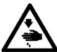 | There is a risk of injury if contacting a moving section. |  | There is a risk of entanglement in the belt resulting in injury. | |
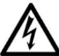 | There is a risk of electrical shock if contacting a high-voltage section. | Indication label | 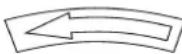 | The correct direction is indicated. | |
 | There is a risk of a burn if contacting a high-temperature section. |  | Connection of a earth cable is indicated. |
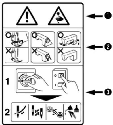
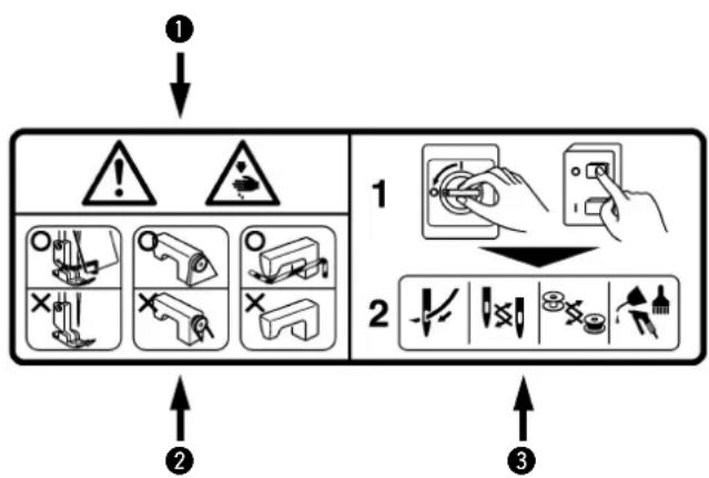
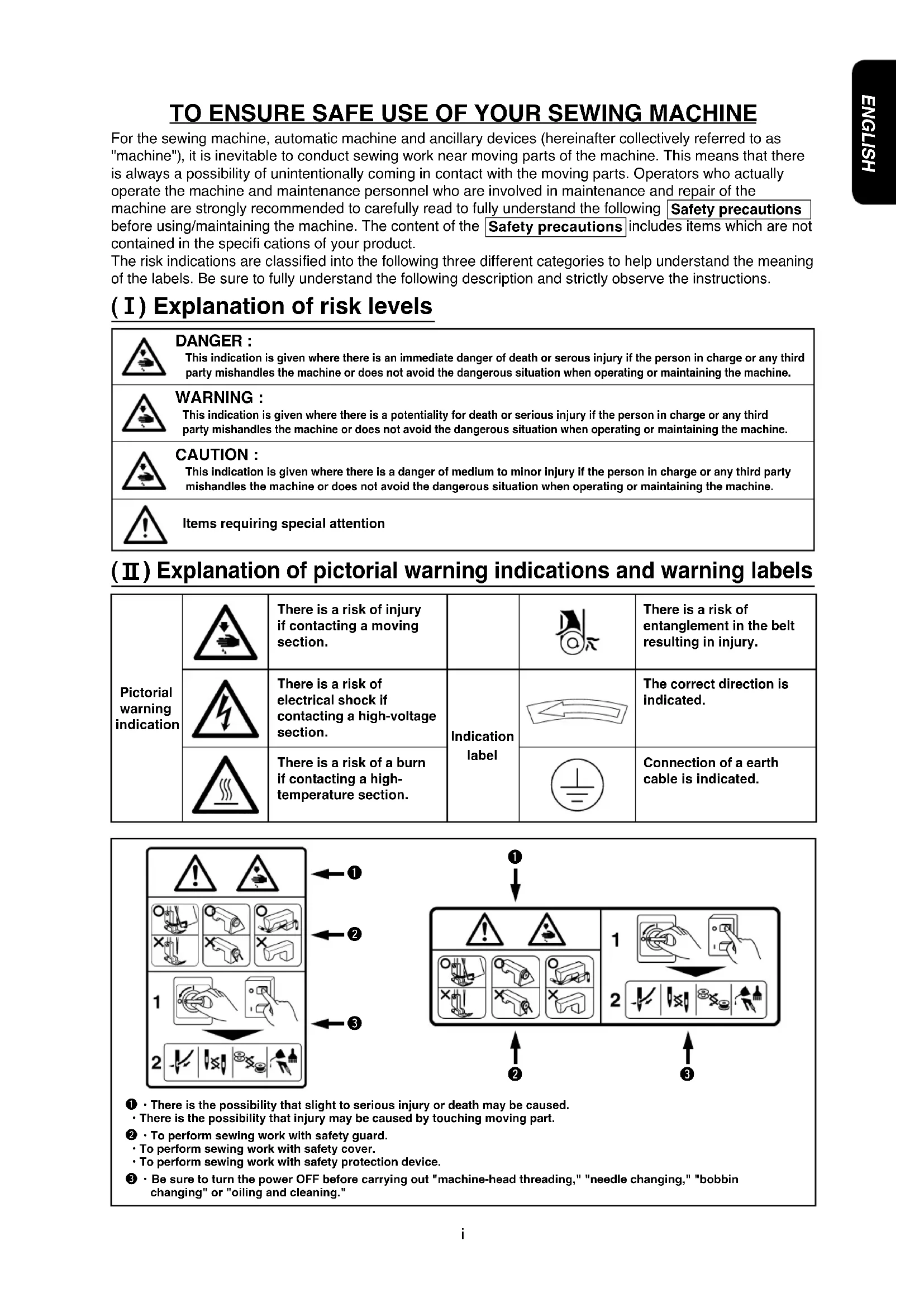
flowchart
graph TD
    A["1"] --> B["Warning"]
    B --> C["Action"]
    C --> D["Edit"]
    D --> E["Control Panel"]
    E --> F["2"]
    F --> G["Check Point"]
    G --> H["End"]
① · There is the possibility that slight to serious injury or death may be caused.
- There is the possibility that injury may be caused by touching moving part.
② · To perform sewing work with safety guard.
• To perform sewing work with safety cover.
• To perform sewing work with safety protection device.
③ · Be sure to turn the power OFF before carrying out "machine-head threading," "needle changing," "bobbin changing" or "oiling and cleaning."

DANGER
- When it is necessary to open the control box containing electrical parts, be sure to turn the power off and wait for five minutes or more before opening the cover in order to prevent accident leading to electrical shock.

CAUTION
Basic precaution
- Be sure to read the instruction manual and other explanatory documents supplied with accessories of the machine before using the machine. Carefully keep the instruction manual and the explanatory documents at hand for quick reference.
- The content of this section includes items which are not contained in the specifications of your product.
- Be sure to wear safety goggles to protect against accident caused by needle breakage.
- Those who use a heart pacer have to use the machine after consultation with a medical specialist.
Safety devices and warning labels
- Be sure to operate the machine after verifying that safety device(s) is correctly installed in place and works normally in order to prevent accident caused by lack of the device(s).
- If any of the safety devices is removed, be sure to replace it and verify that it works normally in order to prevent accident that can result in personal injury or death.
- Be sure to keep the warning labels adhered on the machine clearly visible in order to prevent accident that can result in personal injury or death. If any of the labels has stained or come unstuck, be sure to change it with a new one.
Application and modification
- Never use the machine for any application other than its intended one and in any manner other than that prescribed in the instruction manual in order to prevent accident that can result in personal injury or death. JUKI assumes no responsibility for damages or personal injury or death resulting from the use of the machine for any application other than the intended one.
- Never modify and alter the machine in order to prevent accident that can result in personal injury or death. JUKI assumes no responsibility for damages or personal injury or death resulting from the machine which has been modified or altered.
Education and training
- In order to prevent accident resulting from unfamiliarity with the machine, the machine has to be used only by the operator who has been trained/educated by the employer with respect to the machine operation and how to operate the machine with safety to acquire adequate knowledge and operation skill. To ensure the above, the employer has to establish an education/training plan for the operators and educate/train them beforehand.
Items for which the power to the machine has to be turned off
Turning the power off: Turning the power switch off, then removing the power plug from the outlet. This applies to the following.
- Be sure to immediately turn the power off if any abnormality or failure is found or in the case of power failure in order to protect against accident that can result in personal injury or death.
- To protect against accident resulting from abrupt start of the machine, be sure to carry out the following operations after turning the power off. For the machine incorporating a clutch motor, in particular, be sure to carry out the following operations after turning the power off and verifying that the machine stops completely.
2-1. For example, threading the parts such as the needle, looper, spreader etc. which have to be threaded, or changing the bobbin.
2-2. For example, changing or adjusting all component parts of the machine.
2-3. For example, when inspecting, repairing or cleaning the machine or leaving the machine. - Be sure to remove the power plug by holding the plug section instead of the cord section in order to prevent electrical-shock, earth-leakage or fire accident.
- Be sure to turn the power off whenever the machine is left unattended between works.
- Be sure to turn the power off in the case of power failure in order to prevent accident resulting of breakage of electrical components.
PRECAUTIONS TO BE TAKEN IN VARIOUS OPERATION STAGES
Transportation
-
Be sure to lift and move the machine in a safe manner taking the machine weight in consideration. Refer to the text of the instruction manual for the mass of the machine.
-
Be sure to take sufficient safety measures to prevent falling or dropping before lifting or moving the machine in order to protect against accident that can result in personal injury or death.
-
Once the machine has been unpacked, never re-pack it for transportation to protect the machine against breakage resulting from unexpected accident or dropping.
Unpacking
-
Be sure to unpack the machine in the prescribed order in order to prevent accident that can result in personal injury or death. In the case the machine is crated, in particular, be sure to carefully check nails. The nails have to be removed.
-
Be sure to check the machine for the position of its center of gravity and take it out from the package carefully in order to prevent accident that can result in personal injury or death.
Installation
( I ) Table and table stand
- Be sure to use JUKI genuine table and table stand in order to prevent accident that can result in personal injury or death. If it is inevitable to use a table and table stand which are not JUKI genuine ones, select the table and table stand which are able to support the machine weight and reaction force during operation.
- If casters are fitted to the table stand, be sure to use the casters with a locking mechanism and lock them to secure the machine during the operation, maintenance, inspection and repair in order to prevent accident that can result in personal injury or death.
(Ⅱ) Cable and wiring
-
Be sure to prevent an extra force from being applied to the cable during the use in order to prevent electrical-shock, earth-leakage or fire accident. In addition, if it is necessary to cable near the operating section such as the V-belt, be sure to provide a space of 30 mm or more between the operating section and the cable.
-
Be sure to avoid starburst connection in order to prevent electrical-shock, earth-leakage or fire accident.
-
Be sure to securely connect the connectors in order to prevent electrical-shock, earth-leakage or fire accident. In addition, be sure to remove the connector while holding its connector section.
(III) Grounding
-
Be sure to have an electrical expert install an appropriate power plug in order to prevent accident caused by earth-leakage or dielectric strength voltage fault. In addition, be sure to connect the power plug to the grounded outlet without exceptions.
-
Be sure to ground the earth cable in order to prevent accident caused by earth leakage.
(IV) Motor
-
Be sure to use the specified rated motor (JUKI genuine product) in order to prevent accident caused by burnout.
-
If a commercially available clutch motor is used with the machine, be sure to select one with an entanglement preventive pulley cover in order to protect against being entangled by the V-belt.
Before operation
-
Be sure to make sure that the connectors and cables are free from damage, dropout and looseness before turning the power on in order to prevent accident resulting in personal injury or death.
-
Never put your hand into the moving sections of the machine in order to prevent accident that can result in personal injury or death. In addition, check to be sure that the direction of rotation of the pulley agrees with the arrow shown on pulley.
-
If the table stand with casters is used, be sure to secure the table stand by locking the casters or with adjusters, if provided, in order to protect against accident caused by abrupt start of the machine.
During operation
-
Be sure not to put your fingers, hair or clothing close to the moving sections such as the handwheel, hand pulley and motor or place something near those sections while the machine is in operation in order to prevent accident caused by entanglement that can result in personal injury or death.
-
Be sure not to place your fingers near the surround area of the needle or inside the thread take-up lever cover when turning the power on or while the machine is in operation in order to prevent accident that can result in personal injury or death.
-
The machine runs at a high speed. Never bring your hands near the moving sections such as looper, spreader, needle bar, hook and cloth trimming knife during operation in order to protect your hands against injury. In addition, be sure to turn the power off and check to be sure that the machine completely stops before changing the thread.
-
Be careful not to allow your fingers or any other parts of your body to be caught between the machine and table when removing the machine from or replacing it on the table in order to prevent accident that can result in personal injury or death.
-
Be sure to turn the power off and check to be sure that the machine and motor completely stop before removing the belt cover and V-belt in order to prevent accident caused by abrupt start of the machine or motor.
-
If a servomotor is used with the machine, the motor does not produce noise while the machine is at rest. Be sure not to forget to turn the power off in order to prevent accident caused by abrupt start of the motor.
-
Never use the machine with the cooling opening of the motor power box shielded in order to prevent fire accident by overheat.
Lubrication
- Be sure to use JUKI genuine oil and JUKI genuine grease to the parts to be lubricated.
- If the oil adheres on your eye or body, be sure to immediately wash it off in order to prevent inflammation or irritation.
- If the oil is swallowed unintentionally, be sure to immediately consult a medical doctor in order to prevent diarrhea or vomiting.
Maintenance
-
In prevention of accident caused by unfamiliarity with the machine, repair and adjustment has to be carried out by a service technician who is thoroughly familiar with the machine within the scope defined in the instruction manual. Be sure to use JUKI genuine parts when replacing any of the machine parts. JUKI assumes no responsibility for any accident caused by improper repair or adjustment or the use of any part other than JUKI genuine one.
-
In prevention of accident caused by unfamiliarity with the machine or electrical-shock accident, be sure to ask an electrical technician of your company or JUKI or distributor in your area for repair and maintenance (including wiring) of electrical components.
-
When carrying out repair or maintenance of the machine which uses air-driven parts such as an air cylinder, be sure to remove the air supply pipe to expel air remaining in the machine beforehand, in order to prevent accident caused by abrupt start of the air-driven parts.
-
Be sure to check that screws and nuts are free from looseness after completion of repair, adjustment and part replacement.
-
Be sure to periodically clean up the machine during its duration of use. Be sure to turn the power off and verify that the machine and motor stop completely before cleaning the machine in order to prevent accident caused by abrupt start of the machine or motor.
-
Be sure to turn the power off and verify that the machine and motor stop completely before carrying out maintenance, inspection or repair of the machine. (For the machine with a clutch motor, the motor will keep running for a while by inertia even after turning the power off. So, be careful.)
-
If the machine cannot be normally operated after repair or adjustment, immediately stop operation and contact JUKI or the distributor in your area for repair in order to prevent accident that can result in personal injury or death.
-
If the fuse has blown, be sure to turn the power off and eliminate the cause of blowing of the fuse and replace the blown fuse with a new one in order to prevent accident that can result in personal injury or death.
-
Be sure to periodically clean up the air vent of the fan and inspect the area around the wiring in order to prevent fi re accident of the motor.
Operating environment
-
Be sure to use the machine under the environment which is not affected by strong noise source (electromagnetic waves) such as a high-frequency welder in order to prevent accident caused by malfunction of the machine.
-
Never operate the machine in any place where the voltage fluctuates by more than "rated voltage ± 10% in order to prevent accident caused by malfunction of the machine.
-
Be sure to verify that the air-driven device such as an air cylinder operates at the specified air pressure before using it in order to prevent accident caused by malfunction of the machine.
-
To use the machine with safety, be sure to use it under the environment which satisfies the following conditions:
Ambient temperature during operation 5°C to 35°C
Relative humidity during operation 35 % to 85 %
-
Dew condensation can occur if bringing the machine suddenly from a cold environment to a warm one. So, be sure to turn the power on after having waited for a sufficient period of time until there is no sign of water droplet in order to prevent accident caused by breakage or malfunction of the electrical components.
-
Be sure to stop operation when lightning flashes for the sake of safety and remove the power plug in order to prevent accident caused by breakage or malfunction of the electrical components.
-
Depending on the radio wave signal condition, the machine may generate noise in the TV or radio. If this occurs, use the TV or radio with kept well away from the machine.
-
For the worker who is involved in the work to be done in the environment relevant to "noise value in the working environment is 85 dB or more and less than 90 dB", be sure to take appropriate measures, as required, such as the use of ear protection or the like to protect against health hazard. In addition, for the worker who is involved in the work to be done in the environment relevant to "noise level in the working environment is 90 dB or more," be sure to instruct him/her to wear ear protection without exceptions in order to protect against health hazard, and display a sign explaining how to use the ear protection at an easily viewable location for the worker.
FOR SAFE OPERATION
 | 1. Keep your hands away from the needle when you turn the power switch ON or while the machine is operating.2. Do not put your fingers into the thread take-up cover while the machine is operating.3. Keep your fingers, head hair or clothes away from the vicinity of the handwheel and thread take-up lever or keep clean this area while the sewing machine is running.4. Never operate the machine with the fi nger guard removed. |
 | 1. To achieve, security, be sure that the power supply earth wire has been connected before operating the sewing machine.2. Before inserting/removing the power plug, the power switch has to be turned OFF in advance.3. In time of thunder and lightning, stop your work and disconnect the power plug from the receptacle so as to ensure safety.4. When you move the unit from a cold place directly to a warm place, dew condensation may result. Turn ON the power to the unit after you have confirmed there is no fear of dew condensation.5. To prevent fires, periodically draw out the power plug from the plug socket and clean the root of the pins and the space between pins.6. The looper oscillates at a high speed while you are operating the sewing machine. To protect your hands, keep your hands away from the vicinity of the looper. In addition, be sure to turn the power OFF before threading the machine head.7. To avoid possible accidents due to abrupt start of the machine, be sure to turn OFF the power to the machine.8. Be careful of handling this product so as not to pour water or oil, shock by dropping, and the like since this product is a precision instrument. |

CAUTION :
Note that safety devices such as “eye guard”, “finger guard”, etc. may be omitted from the illustrations in this Instruction Manual for easy explanation.
When operating the machine, be sure not to remove these safety devices.
BEFORE OPERATION

CAUTION :
Check the following so as to prevent maloperation of and damage to the machine.
- Before you put the machine into operation for the first time after the set-up, clean it thoroughly. Remove all dust gathering during transportation and oil it well.
• Confi rm that voltage has been correctly set.
Confirm that the power plug has been properly connected to the power supply.
- Never use the machine in the state where the voltage type is different from the designated one.
- The direction of normal rotation of the machine is counterclockwise as observed from the pulley side. Take care not to allow the machine to rotate in the reverse direction.
• Never operate the sewing machine unless the sewing machine is sufficiently lubricated. - To operate the sewing machine, be sure to install the sewing machine on the table. Then, turn ON the power switch.
- Be sure to remove thread from the machine head and looper before starting a trial run.
- Be sure to use your sewing machine with the speed of stitch lowered to 3,300 sti/min or less for the first month after installation.
- Operate the handwheel after the machine has totally stopped.
DECLARATION OF INCORPORATION OF PARTLY COMPLETED MACHINERY
We hereby declare that the sewing machine (sewing head) described below ;
- Must not be put into service until the machinery to which it is incorporated has been declared inconformity with the provisions of the Directive 2006/42/EC, and
- Conforms to the essential requirements of the Directive 2006/42/EC, described in the technical documentation, and
- To be prepared with the above technical documentation compiled in accordance with part B of Annex VII, and
- Relevant information on which should be transmitted in response to a reasoned request by the national authorities, by the electronic method or other according to the request.
Model MS-1190/V045, V046
MS-1190M/V045, V046
Serial No
Description Industrial Sewing Machine
Function make stitches and sew
Applied harmonized standards, in particular :
EN ISO12100-1, EN ISO12100-2, EN ISO10821
Manufacturer :
JUKI CORPORATION
2-11-1, Tsurumaki, Tama-shi, Tokyo, Japan
CONTENTS
SPECIFICATIONS .... 1
- SETTING UP THE SEWING MACHINE .... 1
- ADJUSTING THE BELT TENSION .... 2
- INSTALLING THE THREAD STAND 2
- INSTALLING THE KNEE LIFTER 2
- LUBRICATION....3
-
ATTACHING A NEEDLE....3
-
THREADING THE MACHINE HEAD .... 4
-
THREAD TENSION ...... 6
-
ADJUSTING THE PRESSURE OF THE PRESSER FOOT 6
-
ADJUSTING THE STITCH LENGTH 7
-
ADJUSTING THE LOOPER CAM 7
-
HEIGHT OF THE FEED DOG....8
-
TIMING TO RELEASE THE NEEDLE THREAD TENSION 8
-
ADJUSTING THE POSITION OF THE NEEDLE THREAD TAKE-UP LEVER GUIDE (MS-1190/V045, MS-1190/V046) 8
-
ADJUSTING THE INTERMEDIATE THREAD GUIDE (MS-1190M/V045, MS-1190M/V046)....9
-
MOTOR PULLEY AND SEWING SPEED 9
-
HOW TO ADJUST THE V045, V046 .... 10
-
TABLE OF REPLACEABLE GAUGES ...... 12
SPECIFICATIONS
| Model MS-1190/V045 MS | -1190/V046 MS-1190M/V045 MS-1190M/V046 | |||
| Application For light-weight materials For medium-weigth materials | ||||
| Number of needle 2 | ||||
| Sewing speed Max. 4,000 sti/min (normal 3,500 sti/min) | ||||
| Needle | ORGAN TV x 64-NY #8 to #14 | ORGAN TV x 64-NY #12 to #19 | ||
| (standard #12) | (standard #16) | |||
| SCHMETZ B-64 Nm. 60 to Nm. 90 SCHMETZ B-64 Nm. 80 to Nm. 120 | ||||
| (standard Nm. 80) | (standard Nm. 100) | |||
| Height of presser foot | 10 mm | |||
| Feed system | Intermittent feed by means of a one-touch utility clutch Link rate adjustable | |||
| Stitch length | 1.2 to 3.2 mm (with a cloth puller) | |||
| Needle gauge | 1/8", 5/32", 3/16", 7/32", 1/4") | |||
| Circumference of cylinder | 171 mm | |||
| Lubricating oil | JUKI New Defrix Oil No.1 | |||
| Noise | Equivalent continuous emission sound pressure level (LpA) at the workstation: A-weighted value of 81.5 dB; (Includes KpA = 2.5 dB); according to ISO 10821-C.6.2 -ISO 11204 GR2 at 4,000 sti/min.-Sound power level (LwA); A-weighted value of 89.5 dB; (Includes Kwa = 2.5 dB); according to ISO 10821-C.6.2 -ISO 11204 GR2 at 4,000 sti/min. | Equivalent continuous emission sound pressure level (LpA) at the workstation: A-weighted value of 80.0 dB; (Includes KpA = 2.5 dB); according to ISO 10821-C.6.2 -ISO 11204 GR2 at 4,000 sti/min. | Equivalent continuous emission sound pressure level (LpA) at the workstation: A-weighted value of 81.5 dB; (Includes KpA = 2.5 dB); according to ISO 10821-C.6.2 -ISO 11204 GR2 at 4,000 sti/min.-Sound power level (LwA); A-weighted value of 90.5 dB; (Includes Kwa = 2.5 dB); according to ISO 10821-C.6.2 -ISO 11204 GR2 at 4,000 sti/min. | Equivalent continuous emission sound pressure level (LpA) at the workstation: A-weighted value of 80.0 dB; (Includes KpA = 2.5 dB); according to ISO 10821- C.6.2 -ISO 11204 GR2 at 4,000 sti/min. |
| Model | V045 | V046 |
| Application Cloth puller for light- to extra-heavy-weight materials | ||
| Cloth puller type | Upper roller feed | Upper/lower roller feed |
1. SETTING UP THE SEWING MACHINE
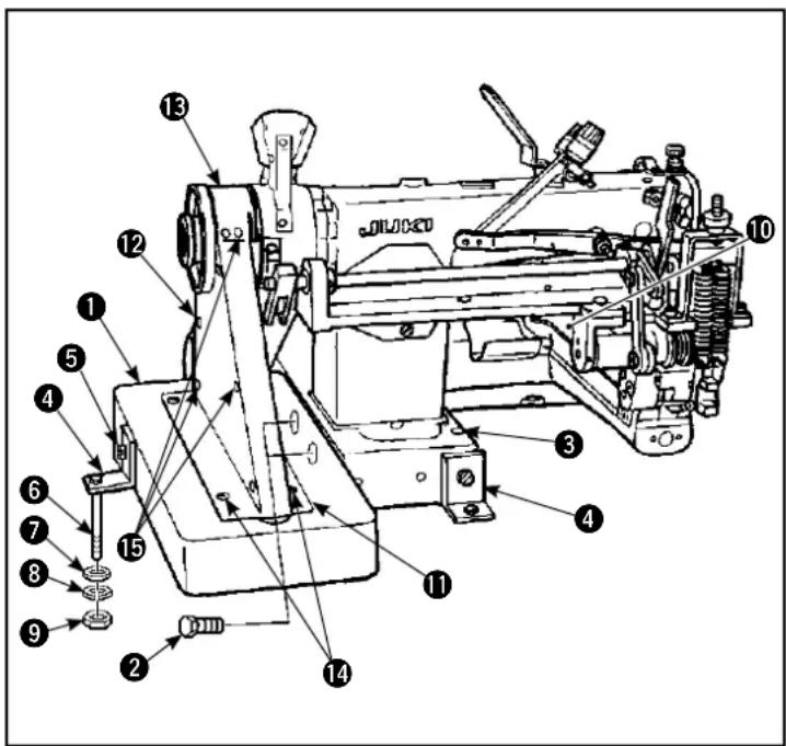
(Caution) Do not hold the pulley.
1) When carrying the sewing machine, be sure to carry by two people.
2) Do not place a protruding object, such as a screw driver, at a place where the sewing machine is to be installed.
3) Attach belt dodging base ① to the sewing machine with hexagon head bolt ②.
4) Put the sewing machine on the table and determine its position (belt groove and through hole ③ for passing the presser bar lifter chain).
5) Attach two machine head support plates ^4 to the sewing machine by means of screw ^5 . Fix the plates on the table by means of hexagonal bolt ^6 , washer ^7 , spring washer ^8 and nut ^9 .
6) Place a level on bed side plate 10 in a lateral direction and a longitudinal direction to check that the sewing machine is properly placed in a horizontal position.
7) Install belt cover ⑪, V belt, belt cover lid ⑫, and top cover ⑬ on the sewing machine and fix them with screws ⑭ and ⑮.
When installing the belt over, temporarily tighten the screw first. Then, securely tighten the screw after the installation of all related parts.
2. ADJUSTING THE BELT TENSION

WARNING :
To protect against possible personal injury due to abrupt start of the machine, be sure to start the following work after turning the power off and ascertaining that the motor is at rest.
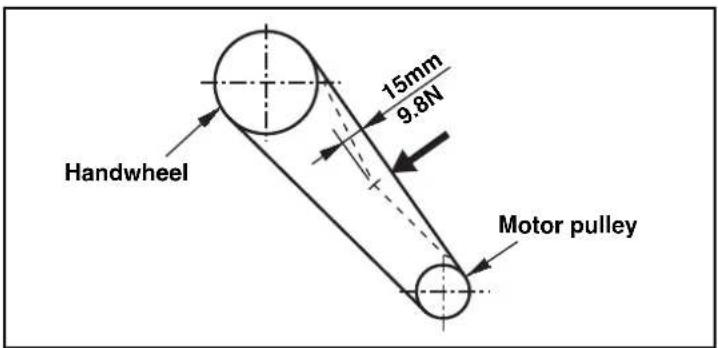
Adjust the belt tension with the height of the motor so that the belt sags 15 mm when the center of V belt is applied with a 9.8N load.
3. INSTALLING THE THREAD STAND
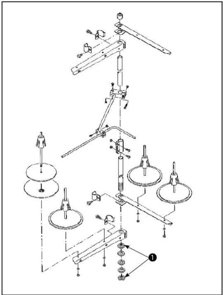
Assemble the thread stand device. Fit it in the hole in the table. Tighten locknut ① so that the thread stand does not fluctuate.
4. INSTALLING THE KNEE LIFTER
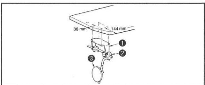
1) Fix knee-lifter mounting base (asm.) ① on the underside of the table using wooden screws.
2) Assemble knee pad vertical shaft (asm.) ③ to knee pad vertical shaft mounting arm ②. Then fix them in the position where you can operate the knee pad with ease.
5. LUBRICATION

WARNING :
To protect against possible personal injury due to abrupt start of the machine, be sure to start the following work after turning the power off and ascertaining that the motor is at rest.
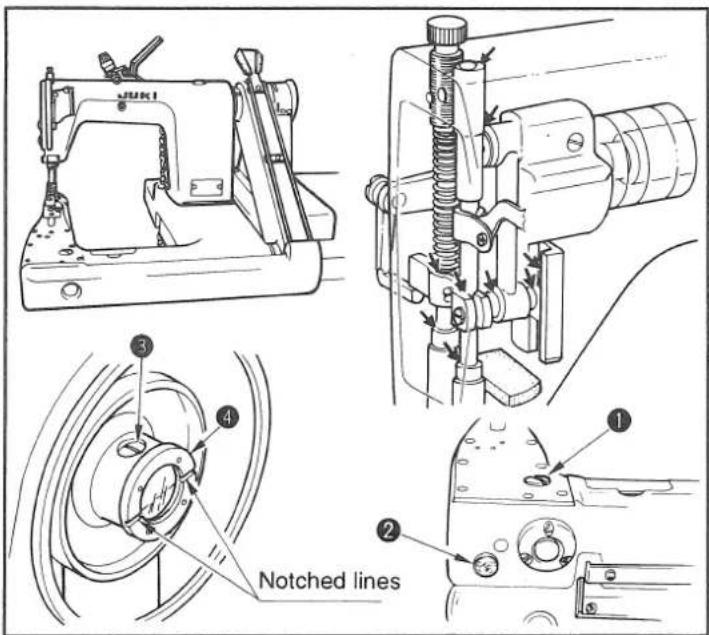
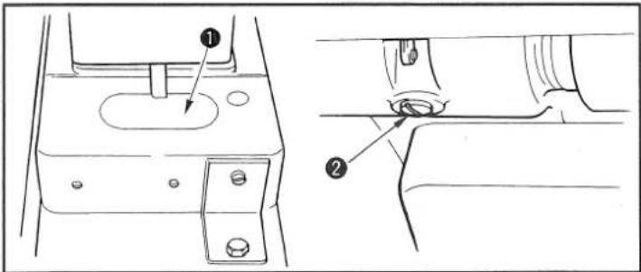
\* Before operating the sewing machine
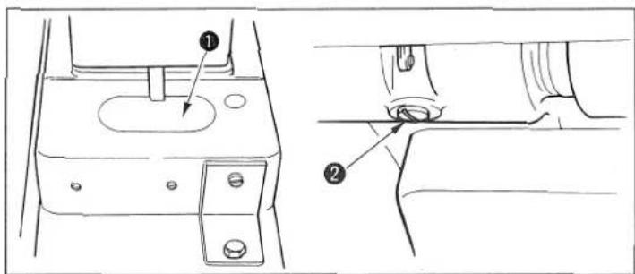
1) Remove screw ① from the lubrication hole. Pour New Defrix Oil No. 1 from the hole until the oil surface reaches the mark on oil sight window ②.
2) Turn the handwheel until the notched lines on the oil cup ④ are leveled. Now, remove screw ③ from the lubrication hole, and pour the oil until the oil surface reaches the notched lines on the oil cup (approx. a half of the oil capacity of the cup).
3) Run the sewing machine for a few minutes, then check the amount of oil again. If the amount of oil is insufficient, pour the oil further until the machine is filled with a proper amount of oil.
4) If the sewing machine has not been used for a long time, lubricate the section marked with an arrow ( ) with a few drops of oil.
(Caution) To operate the sewing machine for the first time after the set-up of the machine or after it has not been used for a long time, fill the oil cup fully with the oil. Check that the oil level is always held within the red marked area on the oil sight window.
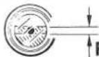
Red marked area
\* Draining oil
1) If the oil has gathered in groove ① of the oil reservoir, wipe it off with rags.
2) Extract the oil which has gathered in the bed, from time to time, by removing cover ② from the draining hole in the hook driving shaft.
6. ATTACHING A NEEDLE

WARNING :
To protect against possible personal injury due to abrupt start of the machine, be sure to start the following work after turning the power off and ascertaining that the motor is at rest.
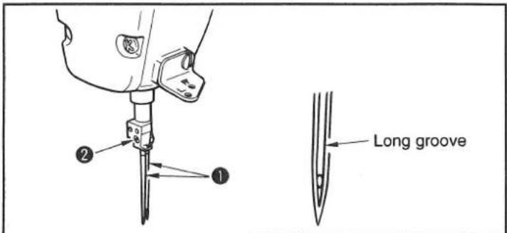
Make a choice of the needle count in accordance with thickness of the thread and type of the material to be used.
1) Turn the handwheel until the needle bar reaches to the highest position of its stroke.
2) Loosen screw ② in the needle clamp, and turn needles ① so that the long groove on the respective needles is brought in front of you.
3) Insert the needles into the needle clamp hole until they will go no further.
4) Securely tighten needle clamp screw ②.
7. THREADING THE MACHINE HEAD

WARNING :
To protect against possible personal injury due to abrupt start of the machine, be sure to start the following work after turning the power off and ascertaining that the motor is at rest.
MS-1190/V045
MS-1190/V046
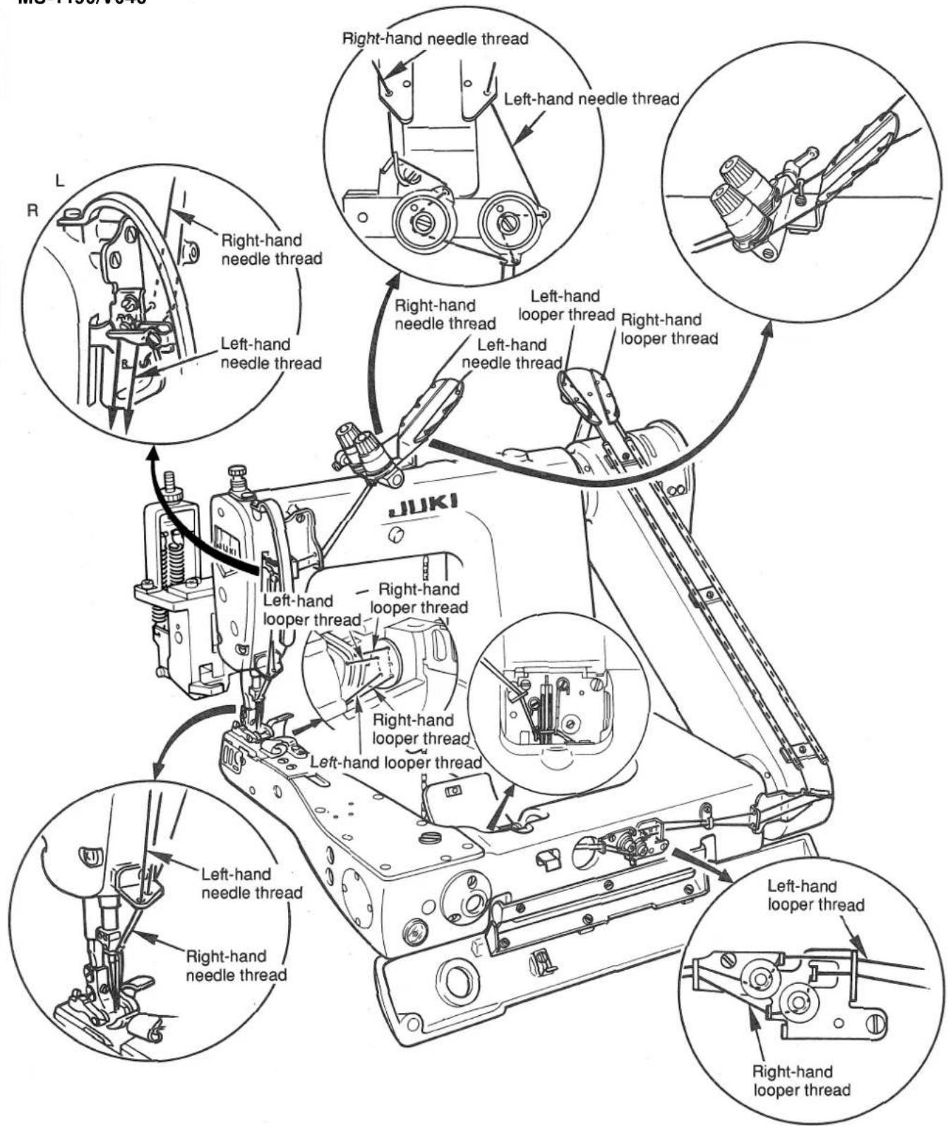
Thread the machine head in the order shown in the figure.
* Pass the needle threads along the marks L and R.
L: Left-hand needle thread R: Right-hand needle thread
MS-1190M/V045
MS-1190M/V046
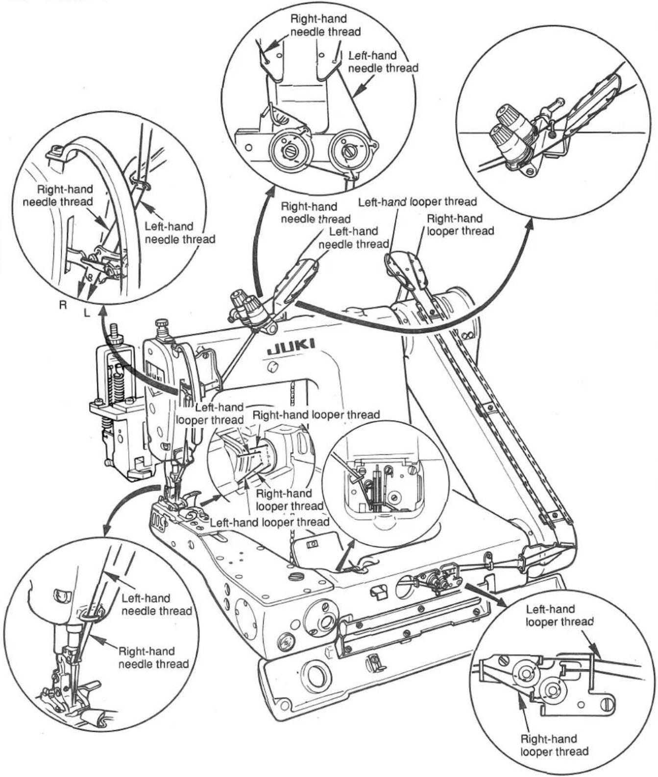
Thread the machine head in the order shown in the figure.
* Pass the needle threads along the marks L and R.
L: Left-hand needle thread R: Right-hand needle thread
8. THREAD TENSION
natural_image
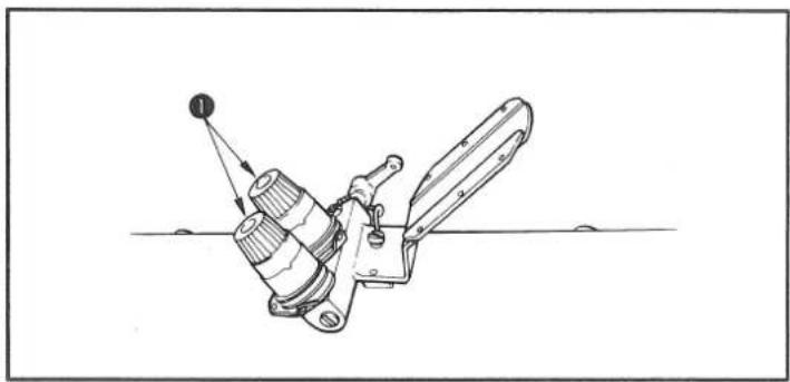
Technical line drawing of a mechanical device with a lever and pivot point (no text or symbols)(1) Adjusting the needle thread tension Turning tension nuts ① clockwise increases the needle thread tension. Turning it counterclockwise decreases the needle thread tension.
natural_image
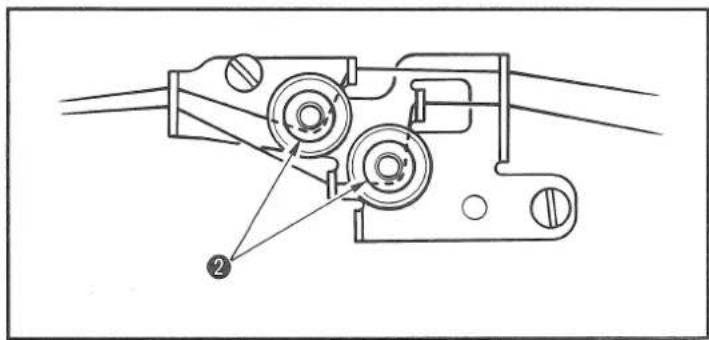
Technical line drawing of a mechanical assembly with two circular components and a numbered label (2), no readable text or symbols present.(2) Adjusting the looper thread tension Turning looper thread tension adjusting knobs ② clockwise increases the looper thread tension. Turning it counterclockwise decreases the looper thread tension.
9. ADJUSTING THE PRESSURE OF THE PRESSER FOOT
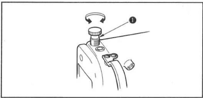
Turning presser spring regulator ① clockwise increases the pressure of the presser foot. Turning it counterclockwise decreases the pressure.
10. ADJUSTING THE STITCH LENGTH

WARNING :
To protect against possible personal injury due to abrupt start of the machine, be sure to start the following work after turning the power off and ascertaining that the motor is at rest.
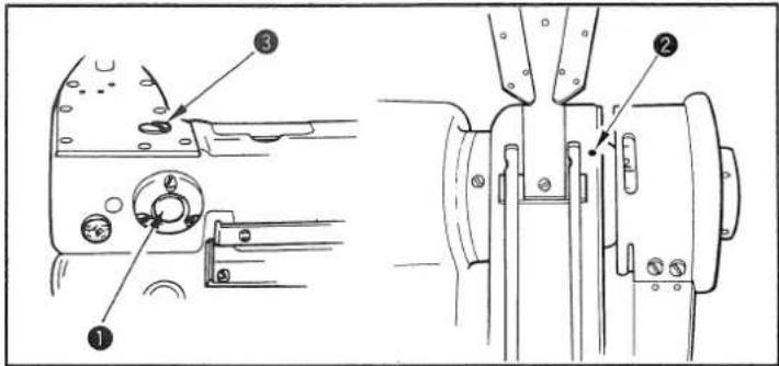
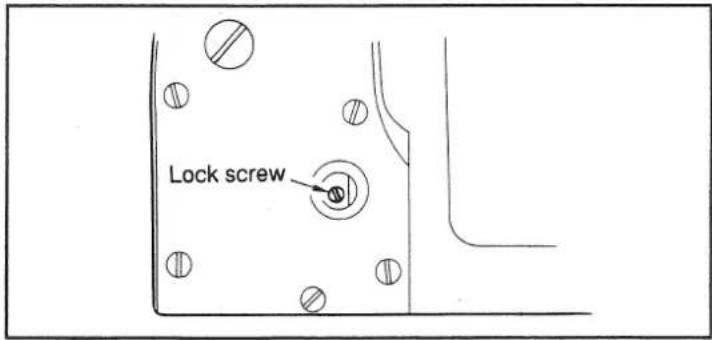
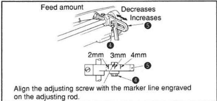
(1) Adjusting the stitch length on the main unit of the sewing machine
1) Remove screw ③, and loosen the lock screw in the feed rock cam.
2) Lightly pressing push-button ①, turn the handwheel by hand.
3) When push button bites, the sewing machine will stop running.
4) In the aforementioned state, further pressing the push-button ①, turn the handwheel by hand.
5) Align the division (indicating the desired value) with marker dot ② engraved on the sprocket gear cover. Then, release the push-button.
6) Tighten the lock screw in the feed rock cam.
7) Attach screw 3 in place.
(Caution) 1. Never press the push-button ① while the sewing machine is in operation.
- Be sure to operate the sewing machine after tightening the lock screw.
- Never operate the machine with screw ③ removed.
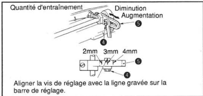
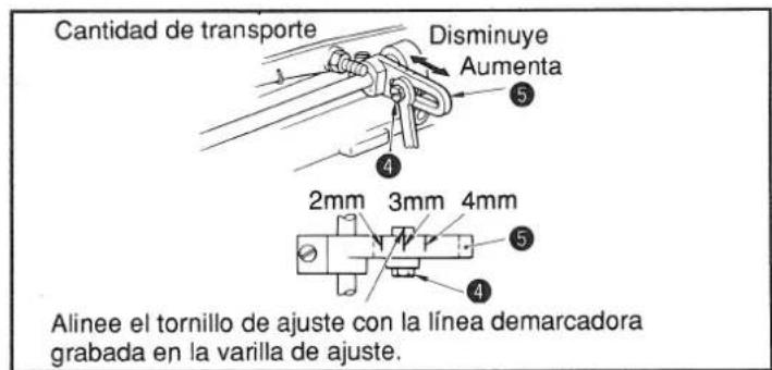
(2) Adjusting the feed amount of the cloth puller
1) Loosen adjusting screw 4.
2) Move the adjustment screw back and forth along the long groove on adjusting rod 5.
3) Tighten adjusting screw ④.
★ The feed amount of the cloth puller can be adjusted nearly to the value shown in the figure on the left by aligning the adjusting screw with one of the divisions engraved on adjusting rod ⑤ corresponding to a feed amount desired.
11. ADJUSTING THE LOOPER CAM

WARNING :
To protect against possible personal injury due to abrupt start of the machine, be sure to start the following work after turning the power off and ascertaining that the motor is at rest.
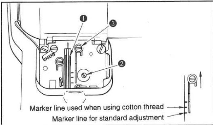
Loosen screw ②, and adjust looper cam ① so that it draws the thread when the looper starts returning to its home position after it has projected the most.
(1) Adjusting the thread guide of the looper thread cam. Adjust the top end of the thread guide to the marker line. The standard position of the thread guide is obtained by adjusting the top end of the thread guide to the marker line located this side.
If cotton thread is used, loosen screw ③ and adjust the top end of the thread guide to the center marker line. At this time, it is not necessary to re-adjust the looper thread cam timing.
12. HEIGHT OF THE FEED DOG

WARNING :
To protect against possible personal injury due to abrupt start of the machine, be sure to start the following work after turning the power off and ascertaining that the motor is at rest.
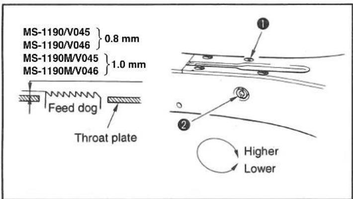
Adjust the projecting amount of the feed dog from the throat plate when the feed dog is lifter the most to 0.8 mm for the MS-1190/V045 and MS-1190/V046, and to 1.0 mm for the MS-1190M/V045 and MS-1190M/V046.
(1) Adjusting the feed dog height
1) Loosen screw ① in the side plate of the bed and remove it.
2) Remove the screw, and you fine a hexagon socket head screw under the screw. Loosen it with an L-shaped hexagon wrench key.
3) Adjust the feed dog height by turning feed driving amount adjusting shaft ②.
4) Fix the shaft with the hexagon socket head screw and tighten screw ①.
(Caution) It is not necessary to firmly fix the feed driving amount adjusting shaft.
13. TIMING TO RELEASE THE NEEDLE THREAD TENSION

WARNING :
To protect against possible personal injury due to abrupt start of the machine, be sure to start the following work after turning the power off and ascertaining that the motor is at rest.
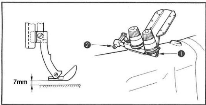
Adjust so that the needle thread tension is released when the presser foot is lifted by 7 mm above the surface of the throat plate. Loosen screw ② in tension releasing shaft ①, and adjust the timing to release the needle thread tension by turning the shaft clockwise or counterclockwise.
14. ADJUSTING THE POSITION OF THE NEEDLE THREAD TAKE-UP LEVER GUIDE (MS-1190/V045, MS-1190/V046)

WARNING :
To protect against possible personal injury due to abrupt start of the machine, be sure to start the following work after turning the power off and ascertaining that the motor is at rest.
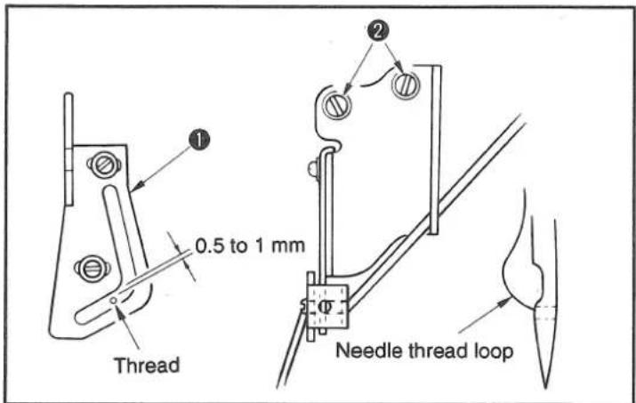
Needle thread loop size is determined by adjusting the position of thread take-up lever guide ①.
The needle thread loop size changes in accordance with the thread and material used. So, adjust the thread loop size upon occasion.
1) Loosen two screws ②, and adjust the position of the thread take-up lever guide by moving it up or down.
2) Adjust so that a clearance of 0.5 to 1 mm is provided between the needle thread and thread take-up lever guide when the needle bar is in its lowest dead point.
3) Lowering the thread take-up lever guide decreases the loop size. Lifting the guide increases it.
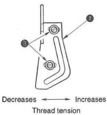
* Type of thread (adjustment to be required by the type of thread such as spun thread and cotton thread)
Needle thread tension can be adjusted by changing the longitudinal position of the thread take-up guide ①. Loosen screws ③ and move the guide back and forth.
Move the guide forward when using an elastic thread (spun thread type, tetron thread type) so as to increase the thread tension. Move it backward when using a thread (cotton thread, etc.) that is not very elastic so as to decrease it.
If the needle thread tension is excessively increased, thread breakage or other stitching troubles will occur. So, carefully adjust the needle thread tension.
15. ADJUSTING THE INTERMEDIATE THREAD GUIDE (MS-1190M/V045, MS-1190M/V046)

WARNING :
To protect against possible personal injury due to abrupt start of the machine, be sure to start the following work after turning the power off and ascertaining that the motor is at rest.
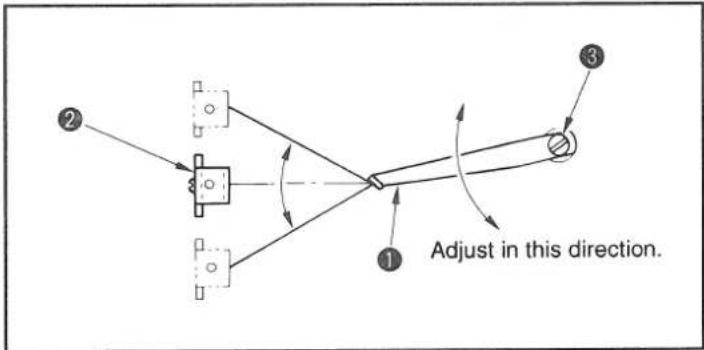
Loosen screw ③, and adjust the position of intermediate thread guide ① so that the thread inclines at equal degrees to horizontal when thread take-up lever ② is in its highest position and lowest position of its stroke.
16. MOTOR PULLEY AND SEWING SPEED
1) Use a clutch motor of 3-phase and 300 W (1/3 HP).
For a servo-motor, a synchronizer mounting base is optionally available.
2) Use an M type V-belt.
3) The relation among the motor pulley, the sewing speed of sewing machine is as shown in the table below:
| Model | Number of revolution of sewing machine | Effective diameter of handwheel | Number of poles of motor | Frequency. | Number of revolution of motor | Effective diameter of motor pulley |
| MS-1190/V045MS-1190/V046MS-1190M/V045MS-1190M/V046 | 4,000 sti/min | 67.4mm 2 | 50Hz 2,865 | rpm 95mm | ||
| 60Hz 3,430 | rpm 80mm | |||||
| 3,600 sti/min | 50Hz 2,865 | rpm 85mm | ||||
| 60Hz 3,430 | rpm 70mm |
* The effective diameter of motor pulley is obtained by subtracting 5 mm from its outside diameter.
* The motor should rotate counterclockwise as observed from the handwheel side. Be careful not to allow the motor to rotate in the reverse direction.
17. HOW TO ADJUST THE V045, V046
Cloth puller
Period of time during which the feed dog rises 0.3 mm above the top surface of the throat plate after is has been flush with it.
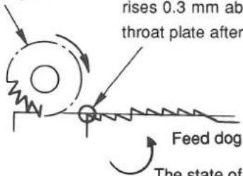
The state of components at the time of starting feeding
Feed amount Decreases
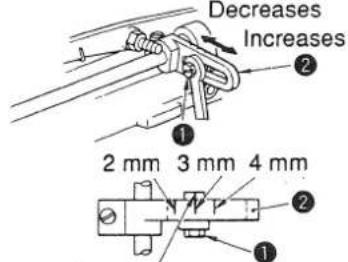
Align the adjusting screw with the marker line engraved on the adjusting rod.
(1) Adjustment of timing between the main body of sewing machine and the V0 device
1) Adjust the amount of feed of the main body of sewing machine to 1.6 mm for the MS-1190/V045 and MS-1190/V046, and to 2.3 mm for the MS-1190M/V045 and MS-1190M/V046.
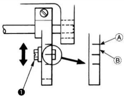
2) Loosen adjusting screw ① of the V0 device. Set the adjusting screw at position A (2.0 mm) for the MS-1190/V045 and MS-1190/V046, and at position B (2.5 mm) for the MS-1190M/V045 and MS-1190M/V046. Then, fi x the adjusting screw.
3) Turning the handwheel, adjust so that the roller starts to rotate during the period of time during which the top end of the feed dog rises 0.3 mm above the top surface of the throat plate surface after is has been flush with the throat plate surface.
(Caution) Confirm the timing to make the roller start to rotate with the presser foot of the sewing machine installed.
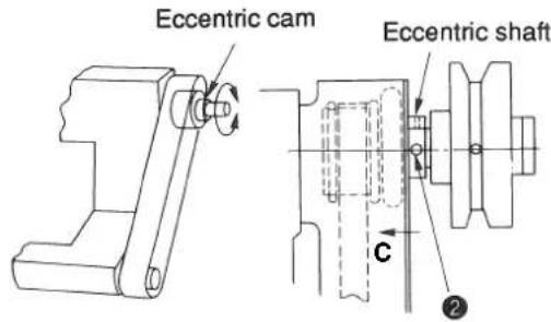
4) Loosen two screws ② in the eccentric cam located inside the handwheel. Then turn the eccentric cam to adjust so that the relation between the cloth puller and the main unit of the sewing machine stated in the aforementioned step 3) is obtained.
5) After the completion of the adjustment, tighten two screws ② while shifting the eccentric cam in direction c.
(2) Adjusting the feed amount
1) Loosen adjusting screw ①.
2) Move the adjustment screw back and forth along the long groove on adjusting rod ②.
★The feed amount of the cloth puller can be adjusted nearly to the value shown in the figure on the left by aligning the adjusting screw with one of the divisions engraved on adjusting rod ② corresponding to a feed amount desired.
3) After the completion of the adjustment of feed amount, tighten adjusting screw ①.
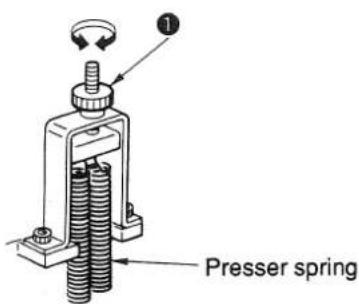
(3) Adjusting the pressing pressure of the roller
The pressing pressure provided by the roller is adjusted by turning presser spring regulator ①.
Turn the presser spring regulator clockwise to increase the pressing pressure of the cloth puller or counterclockwise to decrease it.
(Caution) In the case urethane roller is used, set the roller pressure to a lower value than the set value for the steel roller. An excessive pressure can deform the urethane roller or can apply an extra load to the V0 device.
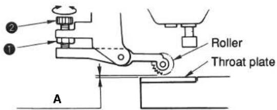
A: V045, V046 In the case of the steel roller → 0.01 to 0.1 mm V045, V046 In the case of the urethane roller → No clearance should be provided between the roller and the throat plate.
(4) Adjusting the clearance provided between the roller and the throat plate
1) Loosen nu①. Adjust the clearance by turning adjusting screw ②.
In the case the steel roller is used:
Adjust the clearance provided between the roller and the throat plate (bottom roller) to 0.01 to 0.1 mm.
In the case the urethane roller is used:
Adjust the clearance provided between the roller and the throat plate (bottom roller) to 0 mm so that no clearance is provided between them.
2) After the adjustment, fix the roller by tightening ①.
(Caution) Adjust so that an appropriate clearance is provided between the roller and the throat plate in accordance with the type of thread to be used.
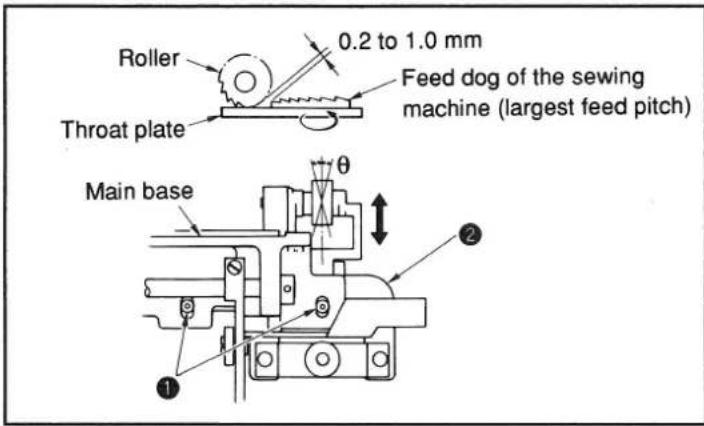
(5) Adjusting the longitudinal position of the roller (V045)
1) Maximize the feed amount of the main unit of the sewing machine. Adjust the longitudinal position of the roller by moving it back or forth so that it is spaced 0.2 to 1.0 mm from the feed dog when the feed dog approaches the roller the most.
2) To adjust, loosen two screws ① and move clutch base ② back or forth.
(Caution) If the roller inclines ( ), chain-off thread will come off the material. So, be sure to adjust so that the roller is in parallel to the feed dog.
18. TABLE OF REPLACEABLE GAUGES
(1) MS-1190/V045, MS-1190M/V045
| Model | 1 | 2 | 3 | 4 | 5 | |||
| Part name | Gauge set(with fi nger guard) | Throat plate Needle clamp (asm.) | Presser foot (asm.)(with fi nger guard) | Feed dog (asm.) | ||||
| Needle gauge | 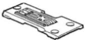 | 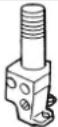 | 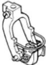 | 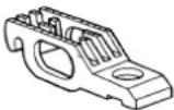 | ||||
| Code inch mm | ||||||||
| MS-1190/V045 | B 1/8 3.2 MAV04570AB0 MAV04570A00 | 12926051 MAV04581AB0 | MAV04593000 | |||||
| C 5/32 4.0 MAV04571BB0 MAV04571B00 | 12926150 MAV04582BB0 | |||||||
| D 3/16 4.8 MAV04572CB0 MAV04572C00 | 12925954 MAV04583CB0 | |||||||
| E 7/32 5.6 MAV04573DB0 MAV04573D00 | 12926259 MAV04584DB0 | |||||||
| F 1/4 6.4 MAV04574EB0 MAV04574E00 | 12926358 MAV04585EB0 MAV04594000 | |||||||
| MS-1190M/V045 | B 1/8 3.2 MAV04575AB0 MAV04575A00 | 12926051 MAV04586AB0 | MAV04595000 | |||||
| C 5/32 4.0 MAV04576BB0 MAV04576B00 | 12926150 MAV04587BB0 | |||||||
| D 3/16 4.8 MAV04577CB0 MAV04577C00 | 12925954 MAV04588CB0 | |||||||
| E 7/32 5.6 MAV04578DB0 MAV04578D00 | 12926259 MAV04589DB0 | |||||||
| F 1/4 6.4 MAV04579EB0 MAV04579E00 | 12926358 MAV04590EB0 MAV04596000 | |||||||
| Model | 6 | 7 | |||
| Part name | Looper (L) (asm.) | Looper (R) (asm.) | |||
| Needle gauge | 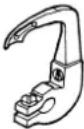 | 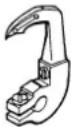 | |||
| Code inch mm | |||||
| MS-1190/V045 | B 1/8 3.2 | 12941555 | 12940656 | ||
| C 5/32 4.0 | 12941654 | 12940755 | |||
| D 3/16 4.8 | 12941456 | 12940557 | |||
| E 7/32 5.6 | 12941753 | 12940854 | |||
| F 1/4 6.4 | 12941852 | 12940953 | |||
| MS-1190M/V045 | B 1/8 3.2 | 12941555 | 12940656 | ||
| C 5/32 4.0 | 12941654 | 12940755 | |||
| D 3/16 4.8 | 12941456 | 12940575 | |||
| E 7/32 5.6 | 12941753 | 12940854 | |||
| F 1/4 6.4 | 12941852 | 12940953 | |||
(2) MS-1190/V046, MS-1190M/V046
| Model | 1 | 2 | 3 | 4 | 5 | |||
| Part name | Gauge set(with fi nger guard) | Throat plate Needle clamp (asm.) | Presser foot (asm.)(with fi nger guard) | Feed dog (asm.) | ||||
| Needle gauge | 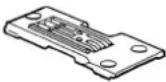 | 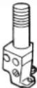 | 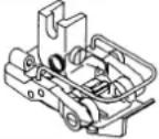 | 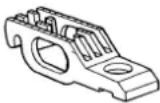 | ||||
| Code inch mm | ||||||||
| MS-1190/V046 | B | 1/8 | 3.2 | 12923561 | 12923504 | 12926051 | 12927869 | 12932307 |
| C | 5/32 | 4.0 | 12923660 | 12923603 | 12926150 | 12927968 | ||
| D | 3/16 | 4.8 | 12923462 | 12923405 | 12925954 | 12927760 | ||
| E | 7/32 | 5.6 | 12923769 | 12923702 | 12926259 | 12928065 | ||
| F | 1/4 | 6.4 | 12923868 | 12923801 | 12926358 | 12928164 | 12932406 | |
| MS-1190M/V046 | B | 1/8 | 3.2 | 12980561 | 12980504 | 12926051 | 12982666 | 12983508 |
| C | 5/32 | 4.0 | 12980660 | 12980603 | 12926150 | 12982765 | ||
| D | 3/16 | 4.8 | 12980462 | 12980405 | 12925954 | 12982567 | ||
| E | 7/32 | 5.6 | 12980769 | 12980702 | 12926259 | 12982864 | ||
| F | 1/4 | 6.4 | 12980868 | 12980801 | 12926358 | 12982963 | 12983607 | |
| Model | 6 | 7 | |||
| Part name | Looper (L) (asm.) | Looper (R) (asm.) | |||
| Needle gauge | [ckww] | 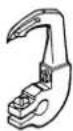 | |||
| Code inch mm | |||||
| MS-1190/V046 | B 1/8 | 3.2 | 12941555 | 12940656 | |
| C 5/3 | 2 4.0 | 12941654 | 12940755 | ||
| D 3/1 | 6 4.8 | 12941456 | 12940557 | ||
| E 7/3 | 2 5.6 | 12941753 | 12940854 | ||
| F 1/4 | 6.4 | 12941852 | 12940953 | ||
| MS-1190M/V046 | B 1/8 | 3.2 | 12941555 | 12940656 | |
| C 5/3 | 2 4.0 | 12941654 | 12940755 | ||
| D 3/1 | 6 4.8 | 12941456 | 12940555 | ||
| E 7/3 | 2 5.6 | 12941753 | 12940854 | ||
| F 1/4 | 6.4 | 12941852 | 12940953 | ||
(3) Folder
| 1 | 2 | 3 | |||
| Part name Folder (asm.) | |||||
| Needle gauge | M295 M296 M | 297 | |||
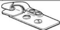 | |||||
| Code inch mm | |||||
| B 1/8 | 3.2 MA | M2950 | AAAA MAM2960AAA | A MAM2970AAAA | |
| C 5/32 | 4.0 M | AM2950 | BBAA MAM2960BB | AA MAM2970BBAA | |
| D 3/1 | 6 4.8 M | AM2950 | CCAA MAM2960CC | AA MAM2970CCAA | |
| E 7/32 | 5.6 M | AM2950 | DDAA MAM2960DD | AA MAM2970DDAA | |
| F 1/4 | 6.4 MA | M2950 | EEAA MAM2960EEAA | A MAM2970EEAA | |
* A folder is not included in the gauge set.
Code of folder
M295 — For extra light-weight materials
M296 — For light-weight materials
(Equipped on MS-1190 as standard)
M297 — For medium-weight materials
(Equipped on MS-1190M as standard)
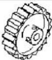
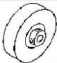
(4) Cloth puller
| 1 | 2 | 3 | 4 | 5 | |||
| Part name Cloth puller (asm.) V045 Cloth puller (asm.) V046 | |||||||
| Needle gauge | Steel roller Urethane roller Steel roller | Urethane roller Bottom roller | |||||
 |  |  |  | [CSAH] | |||
| Code inch mm | |||||||
| B 1/8 3.2 | MAV045450A0 | MAV045500B0 | MAV04640000 | MAV046410A0 | MAV046210B0 | ||
| C 5/32 4.0 | |||||||
| D 3/16 4.8 | |||||||
| E 7/32 5.6 | |||||||
| F 1/4 6.4 | |||||||
* The cloth puller is not included in the gauge set.
Kinds of cloth pullers
Steel roller — For medium-weight materials
Urethane roller — For light to extra light-weight materials
DEUTSCH
natural_image
Technical line drawing of a mechanical device with a lever and pivot point (no text or symbols)natural_image
Technical line drawing of a mechanical assembly with no visible text or symbolsnatural_image
Technical diagram of a mechanical component with labeled parts (no text or symbols present)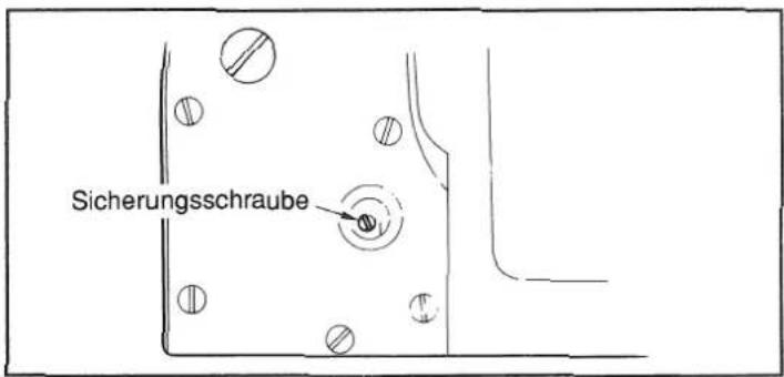
Stoffzieher
natural_image
Technical line drawing of a mechanical device with a lever and pivot point (no text or symbols)natural_image
Technical line drawing of a mechanical assembly with two circular components and a numbered label (2), no readable text or symbols present.natural_image
Technical line drawing of a mechanical component with a knob and adjustment knob (no text or symbols)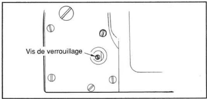
Entraîneur de tissu
flowchart
graph TD
    A["1"] --> B["Warning"]
    B --> C["Action Icon 1"]
    C --> D["Action Icon 2"]
    D --> E["Execution Icon 3"]
natural_image
Technical line drawing of a mechanical device with no visible text or symbolsnatural_image
Technical line drawing of a mechanical assembly with two circular components and connecting rods (no text or symbols)natural_image
Technical line drawing of a mechanical component with a knob and lever (no text or symbols)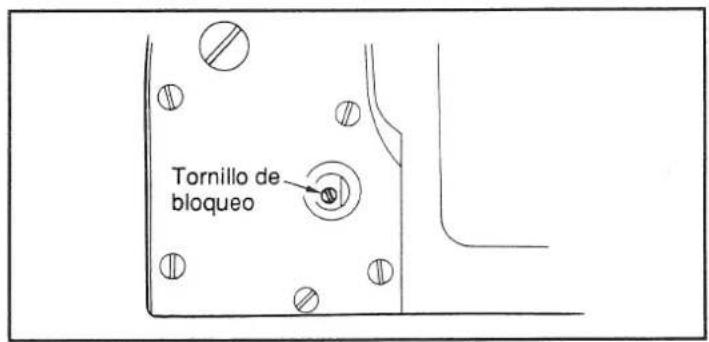
Tirador de tela
natural_image
Technical line drawing of a mechanical device with no visible text or symbolsnatural_image
Technical line drawing of a mechanical assembly with two circular components and a numbered label (2), no readable text or symbols present.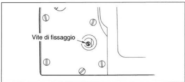
Puller
SEWING MACHINERY BUSINESS UNIT
2-11-1, TSURUMAKI, TAMA-SHI,
Copyright © 2011 JUKI CORPORATION
• All rights reserved throughout the world.
- Alle Rechte weltweit vorbehalten.
- Tous droits réservés partout dans le monde.
- Reservados todos derechos en el mundo entero.
• Tutti i diritti sono riservati in tutto il mondo.
Please do not hesitate to contact our distributors or agents in your area for further information when necessary.
* The description covered in this instruction manual is subject to change for improvement of the commodity without notice.
- TO ENSURE SAFE USE OF YOUR SEWING MACHINE
- Explanation of risk levels
- (Ⅱ) Explanation of pictorial warning indications and warning labels
- DANGER
- CAUTION
- Basic precaution
- Safety devices and warning labels
- Application and modification
- Education and training
- Items for which the power to the machine has to be turned off
- PRECAUTIONS TO BE TAKEN IN VARIOUS OPERATION STAGES
- Transportation
- Unpacking
- Installation
- ( I ) Table and table stand
- (Ⅱ) Cable and wiring
- (III) Grounding
- (IV) Motor
- Before operation
- During operation
- Lubrication
- Maintenance
- Operating environment
- FOR SAFE OPERATION
- CAUTION :
- DECLARATION OF INCORPORATION OF PARTLY COMPLETED MACHINERY
- CONTENTS
- SPECIFICATIONS .... 1
- SETTING UP THE SEWING MACHINE
- (Caution) Do not hold the pulley.
- ADJUSTING THE BELT TENSION
- INSTALLING THE THREAD STAND
- INSTALLING THE KNEE LIFTER
- LUBRICATION
- WARNING :
- \* Before operating the sewing machine
- Red marked area
- \* Draining oil
- ATTACHING A NEEDLE
- THREADING THE MACHINE HEAD
- THREAD TENSION
- ADJUSTING THE PRESSURE OF THE PRESSER FOOT
- ADJUSTING THE STITCH LENGTH
- ADJUSTING THE LOOPER CAM
- HEIGHT OF THE FEED DOG
- TIMING TO RELEASE THE NEEDLE THREAD TENSION
- ADJUSTING THE POSITION OF THE NEEDLE THREAD TAKE-UP LEVER GUIDE (MS-1190/V045, MS-1190/V046)
- ADJUSTING THE INTERMEDIATE THREAD GUIDE (MS-1190M/V045, MS-1190M/V046)
- MOTOR PULLEY AND SEWING SPEED
- HOW TO ADJUST THE V045, V046
- Adjusting the clearance provided between the roller and the throat plate
- Adjusting the longitudinal position of the roller (V045)
- TABLE OF REPLACEABLE GAUGES
- DEUTSCH
Brand : JUKI
Model : MS1190M
Category : Sewing machine