
P10 - Lawn mower Powerworks - Free user manual and instructions
Find the device manual for free P10 Powerworks in PDF.


| Product type | Robotic lawn mower |
| Brand | Powerworks |
| Model | P10 |
| Dimensions (H x L x W) | 26 cm x 62 cm x 50 cm |
| Weight | 11 kg |
| Power supply | 100-240 V / 32 V DC (power adapter) |
| Battery | Lithium-ion 24 V / 2.0 Ah |
| Average charging time | 140 minutes |
| Average cutting time | 70 minutes |
| Cutting system | 3 pivoting blades |
| Cutting width | 22 cm |
| Cutting height | 20 to 60 mm (adjustable) |
| Maximum slope of working area | 35% |
| Maximum recommended area | 700 m² |
| Maximum absolute area | 1,000 m² |
| Maximum boundary wire length | 800 m |
| Sound level (measured/guaranteed) | 58 dB(A) / 60 dB(A) |
| Protection rating (mower) | IPX5 |
| Protection rating (charging station) | IPX2 |
| Protection rating (power supply) | IP67 |
| Main functions | Programming via app, collision detection, automatic return to station, integrated alarm |
| Safety | Safety key, STOP button, PIN code via app |
| Maintenance | Regular cleaning, blade replacement every 2 to 6 weeks |
| Spare parts | Blades (ref. 333092355), battery (ref. 211022355), blade screws, wire connectors |
Frequently Asked Questions - P10 Powerworks
User questions about P10 Powerworks
0 question about this device. Answer the ones you know or ask your own.
Ask a new question about this device
Download the instructions for your Lawn mower in PDF format for free! Find your manual P10 - Powerworks and take your electronic device back in hand. On this page are published all the documents necessary for the use of your device. P10 by Powerworks.
USER MANUAL P10 Powerworks
The following pages contain important safety and operating instructions
Carefully read and review all safety instructions, warnings and cautions contained in this manual.
Failure to read and follow these instructions, warnings and cautionary statements may result in severe injury or death to persons and pets or damage to personal property.
The materials, technical data, and figures in this manual are provided for guidance only and are not binding. The manufacturer reserves the right to make any changes to the technical characteristics and all features of operation, materials, technical data, or figures without prior warning.
Contents
Product Safety 4
Reading the operator manual....4
Operational safety....6
Product Unboxing....7
Installation 8
Planning Layout and Preparation 8
Installing and Connecting the Charging Station....9
Position for the charging station as follows:....9
Connecting the Power Supply.... 10
Initial Charging of the Battery....11
Installing the Boundary Wire....12
Installing a Guide Wire ....15
Calibrating and Initial Start Up....17
Operation....18
Starting and Stopping the Mower....18
Switching Off the Mower....18
Adjusting Cutting Height 18
Lifting and Carrying the Mower....19
Pairing Mobile App to Mower....19
Maintenance....20
Removing the Body from Chassis 20
Cleaning....20
Replacing Blades 21
Maintaining the Battery....21
Replacing the Battery 22
Winter Storage Mower 23
Winter storage Charging Station 23
Troubleshooting....24
Indicator LEDs on Mower 24
Symptoms....25
Breaks in Boundary Wire and Guide Wire....25
Technical Data....26
Environmental Protection....28
Warranty Terms 29
CE Declaration of Conformity....30
As a complement to this operator manual, more information is available on the website: www.Powerworkstools.eu
Explanation of Symbols on the Mower


This is a dangerous power tool. Use care when operating and follow all safety instructions and warnings.
Read the operator manual carefully before operating the mower.


Remove the safety key before working on or lifting the mower.


Hazard of thrown objects during operation.
Keep a safe distance from the mower when operating and keep people, especially children, pets and bystanders away from the area where mower is being operated.


Do not ride on the mower.

Class III appliance
Reading the operator manual
The following symbols are important for reading and understanding the operating instructions.

Wear protective gloves
The following system is used in the operator manual to make it easier to understand:
- WARNING! Warning texts alert users and consumers to the existence and nature of hazards so that they can prevent injury by appropriate conduct during use of the product.
• CAUTION: Caution texts alert users and consumers to the existence and nature of product risks so that they can prevent damaging the product by appropriate conduct during use of the product.
NOTE: Notes inform users and consumers about additional information about product use.
• Text written in bold italics refers to another section in the operator manual.
• Text written in bold refers to settings on the mower.
IMPORTANT
READ CAREFULLY BEFORE USE! KEEP FOR FUTURE REFERENCE!
Training
WARNING! Automatic lawnmower! Keep away from the machine! Supervise children!
- Read the instructions carefully. Be familiar with the controls and the proper use of the machine.
- Never allow people unfamiliar with these instructions or children to use the machine. Local regulations may restrict the age of the operator.
• The operator or user is responsible for accidents or hazards occurring to other people or their property.
Preparation
- Ensure the correct installation of the boundary and guide wires as instructed.
- Periodically inspect the area where the machine is to be used and remove all stones, sticks, wires, bones, and other foreign objects.
- Periodically visually inspect to see that the blades, blade bolts and cutter assembly are not worn or damaged. Replace worn or damaged blades and bolts in sets to preserve balance.
General
• Never operate the machine with defective guards, or without safety devices, for example the body, in place.
- Do not put hands or feet near or under rotating parts.
- Never pick up or carry an machine while the motor is running.
- Remove (or Operate) the disabling device from the machine
-before clearing a blockage;
-before checking, cleaning or working on the machine.
- Do not leave the machine to operate unattended if you know that there are pets, children or people in the vicinity.
Maintenance and storage
- Keep all nuts, bolts, and screws tight to be sure the machine is in safe working condition.
- Replace worn or damaged parts for safety.
- Ensure that only replacement cutting means of the right type are used.
- Ensure that batteries are charged using the correct charger recommended by the manufacturer. Incorrect use may result in electric shock, overheating or leakage of corrosive liquid from the battery.
In the event of leakage of electrolyte flush with water/neutralizing agent, seek medical help if it comes into contact with the eyes, etc.
Servicing of the machine should be according to manufacturers' instructions.
Operational safety
This operator manual contains all of the basic information concerning the safe operation and maintenance of the mower.

Carefully read all the safety precautions and instructions in this operator manual before operating the mower. Save this operator manual for future reference. Follow manufacturer instructions regarding installation, operation, maintenance, and repair.

This mower is designed to mow grass in open and level areas. Use only equipment recommended by the manufacturer. All other types of use are incorrect.

This mower conforms to CE safety standards and directives concerning electromagnetic compatibility, machines, and low voltage.
The mower is not intended for use by persons (including children) with reduced physical, sensory, or mental capabilities, or lack of experience and knowledge, unless they have been given supervision or instruction concerning use of the appliance by a person responsible for their safety.
Children should be supervised to ensure that they do not play with the appliance.
The mower must only be operated, maintained, and repaired by persons that fully understand its special characteristics and safety regulations.
Start the mower in accordance with the instructions. When the safety key is in the Enabled position, keep your hands and feet away from the rotating blades.
Never put your hands and feet under the mower.
Do not modify the original design of the mower. All modifications void the guarantee.
Switch off mower using the STOP button on the mower when persons, especially children, or pets are in the cutting area. It is recommended that the mower be programmed for use during hours when the area is free from persons or pets.
Remove objects from the operating area such as branches, toys, stones, tools that can damage the blades. The mower can fasten on objects in the operating area and help may be required to remove the object before the mower can continue mowing.
Never lift up the mower or carry it with the safety key inserted.
Always switch off the mower using the STOP button when the mower is not in use. The mower can only start when the safety key is inserted and the START button is pressed.
The built-in alarm is very loud. Be careful, especially if the mower is handled indoors.
Do not use the mower with a defective blade disc or body.
Do not let persons who do not know how the mower works and behaves use it.
Do not put anything on top of the mower or its charging station.
Always wear protective gloves when working with the mower's blades.

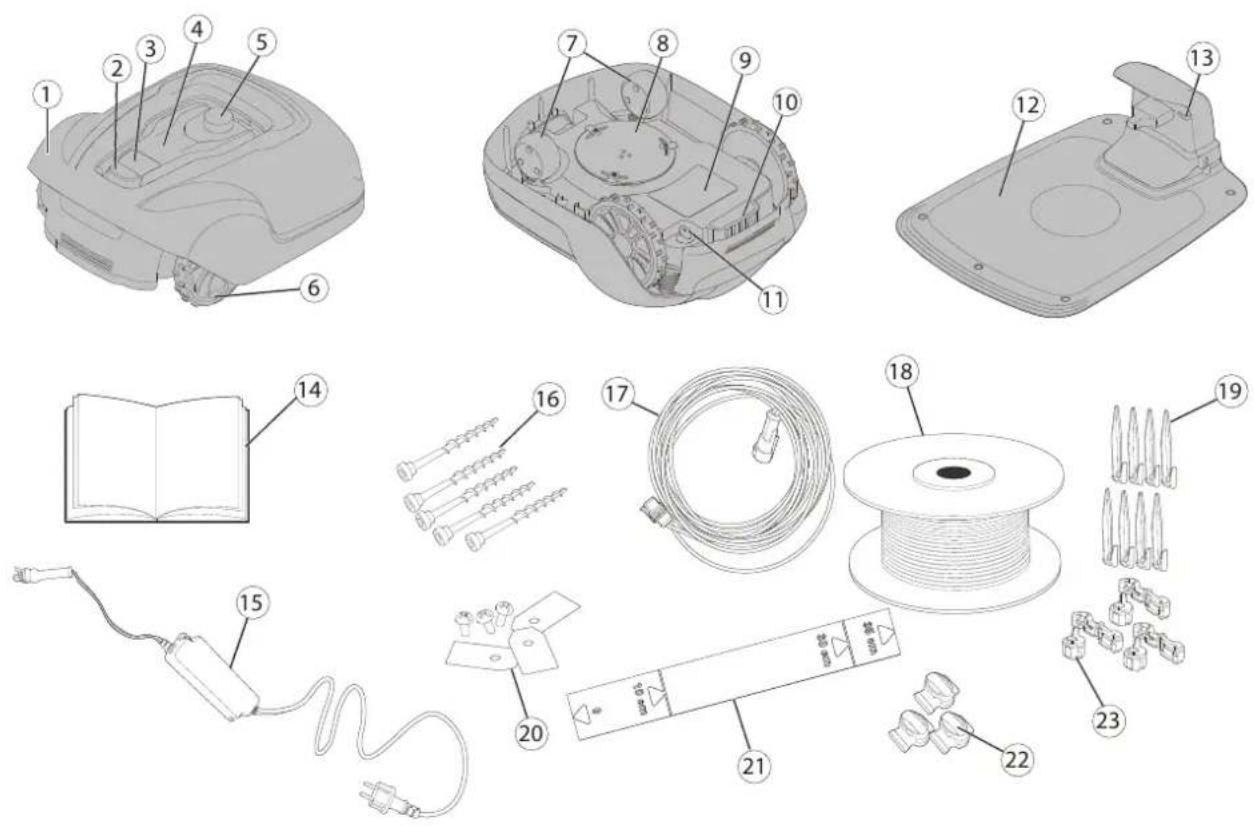
1 Removable cover
2 Stop button
3 Start button
4 LED indicators
5 Cutting height adjustment
6 Rear wheels
7 Front wheels
8 Blade disc
9 Battery cover
10 Carrying handle
11 Safety key
12 Charging station
13 LED for operation check
14 Operator manual and quick guide
15 Power supply*
16 Screws for securing charging station (x5)
17 Low voltage cable
18 Loop wire for boundary and guide wire
19 Wire pegs
20 Extra blades and screws (x3)
21 Ruler (break off carton top)
22 Splice and guide wire connectors
23 Loop wire connectors
* The appearance of the power supply may differ depending on market.
Unbox the mower and installation materials. Make certain that all parts shown in Figure 1 are included and undamaged. Contact your retailer if any items are missing or damaged.
Keep the Quick Guide in a safe place since it contains the unique pairing code for your mower.
Read the entire section before beginning installation. Installation affects mower capability.
Plan the installation carefully.
The following are the main tasks within the installation:
• Planning layout and preparation
• Installing and connecting the charging station
• Connecting the power supply
• Initial charging of the battery
• Installing the boundary wire
• Installing the guide wire
• Calibrating and initial start up
Planning Layout and Preparation
Ensure that the following conditions exist in the operating area where the mower will be used:
• The grass is shorter than 10 cm.
There are no stones, loose pieces of wood, wire, live mains cables, and other foreign objects.
• The operating area is even and has no ditches, grooves, and steep slopes greater than 35%.
The following tools are required for installation, but not included:
- Hammer/rubber mallet to drive the pegs into the ground
• Combination pliers to cut the boundary wire
• Polygrip to press the couplers together
• Hex key, 6 mm for securing the charging station to ground
Installing and Connecting the Charging Station

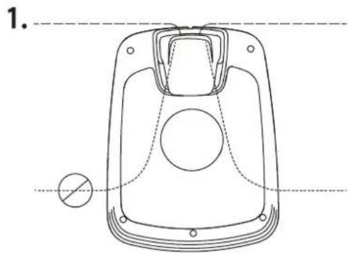
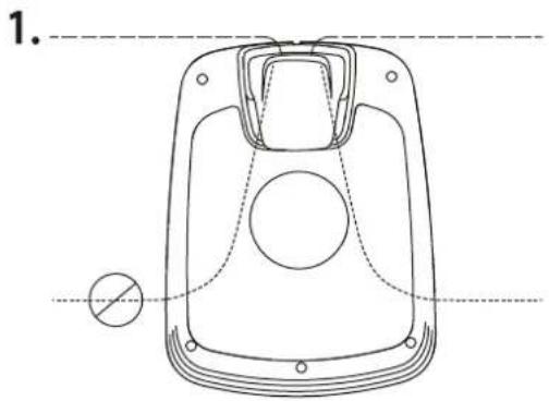
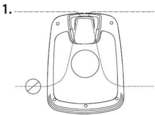
Position for the charging station as follows:
- In a level spot out of direct sunlight
(The front end of the charging station must not be 5 cm higher or lower than the back end.)
• Within reach of a wall socket (The low voltage cable is 10 m long.) - With at least 3 m in front of it and 1 m to each side (Do not position in confined spaces in the operating area.)

The entire charging station must be inside the operating area as shown in the figure.
Connecting the Power Supply
Connect the power supply in a cool, dry environment; out of direct sunlight.
If the power supply is connected to an electrical socket outdoors, it must be approved for outdoor use.
The low voltage cable can cross the operating area if it is stapled down or buried.
CAUTION: Do not cut, splice, or alter the low voltage cable. Altering the low voltage cable will void the product guarantee.

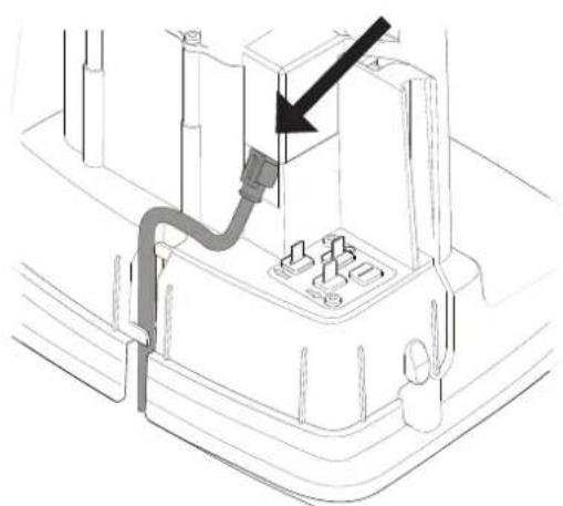
Remove the protective cover on the charging station by pressing in the tabs on each side of the base and lifting away the cover.

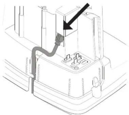
Connect the low voltage cable to the charging station.
Thread the low voltage cable behind the tabs to hold it in place in the charging station.
Connect the power supply power cable to a 100-240 V wall socket.
Initial Charging of the Battery
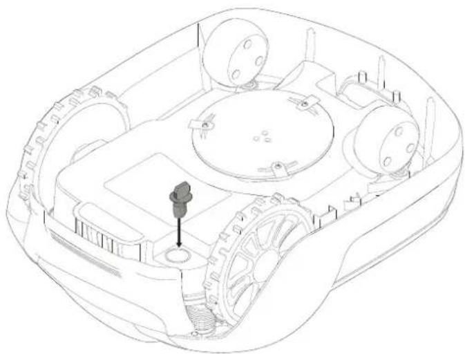
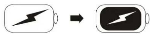

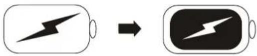
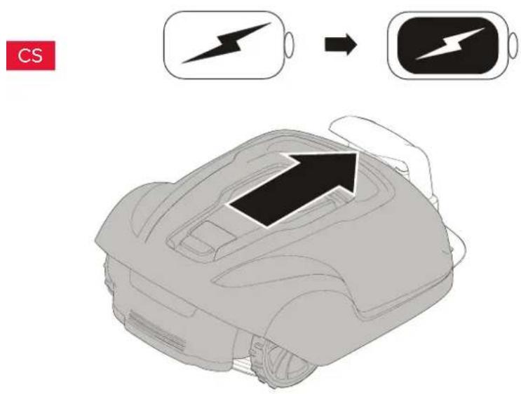
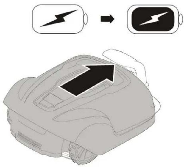
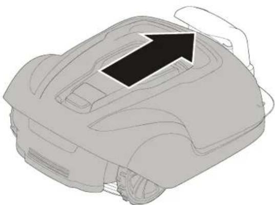
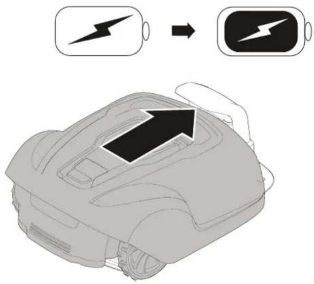
Insert the safety key into the underside of mower and turn to the Enable position.
Place the mower into the charging station while the boundary and guide wires are being laid.
The mower cannot be used before the installation is complete.
Installing the Boundary Wire
When installing the boundary wire there are a number of situations to consider as described in the table below.
Table 1. Handling Deviations and Obstacles in the Operating Area
| Variation within Operating area Boundary Wire Planning | |
| Fixed obstacles level with lawn that the mower can traverse (paving stone paths or similar) | Lay the boundary wire under the paving stones or in the joint between the paving stones.Never run the mower over gravel, mulch, or similar material that can damage the blades. |
| Fixed obstacles ± 1 cm high Lay the boundary wire 10 cm from the obstacle. | |
| Fixed obstacles 1-5 cm high (small ditches, flower beds, or low kerbstones) | Lay the boundary wire 30 cm from the obstacle. |
| Fixed obstacles 5 cm or higher (fences or walls) Lay the boundary wire 35 cm from the obstacle. | |
| Fixed obstacles taller than 15 cm that can withstand a collision (trees or shrubs) | No measures required; the mower will turn around when it collides with this type of obstacle. |
| Fixed obstacles that slope slightly such as stones or large trees with raised roots | Lay the boundary wire 30 cm from or remove obstacle. |
| Fixed obstacles that cannot withstand a collision Lay the boundary wire 30 cm from and around the obstacle and then return it back along the same route. | |
| Long and narrow passages and areas narrower than 1.5 m Install a guide wire. | |
| Borders on a slope, road, precipice, or water Supplement the boundary wire with a physical barrier at least 15 cm high. | |
| Slope up to 35% within operating area No measures required; the mower can operate up to a 35% as long as the slope is not at the boundary of the operating area. | |
| Slope less than 15% at operating area edge Lay boundary wire as normal. | |
| Slope greater than 15% at operating area edge Do not lay boundary wire unless a fixed obstacle (fence or wall) exists to prevent the mower from leaving the operating area.When a part of the operating area outer edge slopes more than 15%; lay the boundary wire 20 cm in on the flat ground before the beginning of the slope. |
NOTE: Slope gradient is defined in percentage units (%). The slope as a percentage unit is calculated as the difference in elevation in centimetres for every metre. If, for example, the difference in elevation is 10 cm, the slope gradient is 10%.
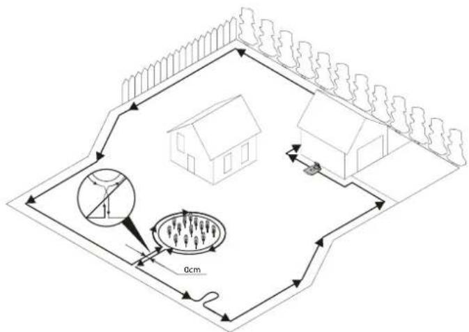

Temporarily secure the end of the loop wire to a peg or other object at the charging station.
Lay out the loop wire in a counter-clockwise direction alone the planned boundary of the operating area taking into consideration the rules in Table 1 until you return to the charging station.
If you are going to install a guide wire, create an eyelet with about 20 cm of extra boundary wire at the point where the guide wire will later be connected.
See Installing a Guide Wire on page 15 for more information.
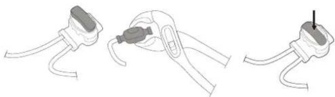
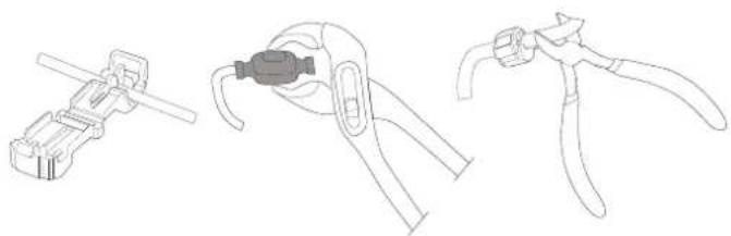
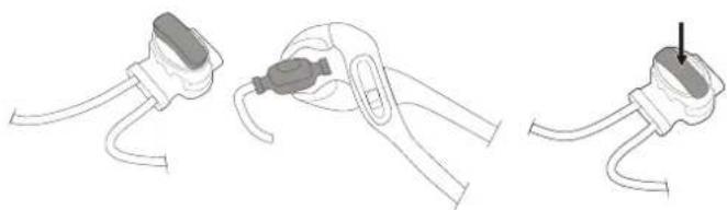
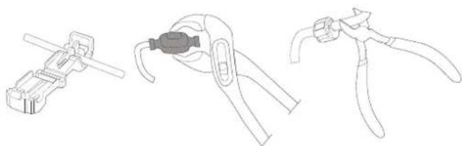
If the boundary wire is too short, use provided splice and guide wire connectors to splice additional boundary wire as follows:
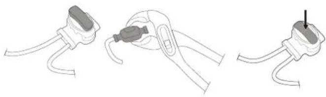
1 Insert both ends of the boundary wire into the splice and guide wire connector. Check that the wires are fully inserted into the splice and guide wire connector so that the ends are visible through the splice and guide wire connector.
2 Squeeze down the button on top of the splice and guide wire connector fully using a polygrip until you hear a click.
Lay down the loop wire reel at the charging station.
Go back around the boundary of the operating area and secure the boundary wire either using pegs or buried in the ground. Pegs are recommended since this allows for adjustment during the first few weeks of operation.
When securing the boundary wire with pegs:
- Cut the grass very low with a standard lawnmower or a trimmer where the wire is to be laid.
- Lay the boundary wire on the ground and secure with pegs close together.
- Push or hammer the pegs into the ground.
Do not push the pegs so far into the ground so that they strain the boundary wire.
When burying the boundary wire:
- Bury the boundary wire 1–20 cm into the ground.

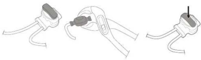
When the boundary wire is completely laid out and secured, install end loop wire connectors as follows:
1 Open the loop wire connector and place the wire in the loop wire connector grip.
2 Press the loop wire connectors together using a polygrip until you hear a click.
Cut off any surplus boundary wire 1-2 cm above each connector.

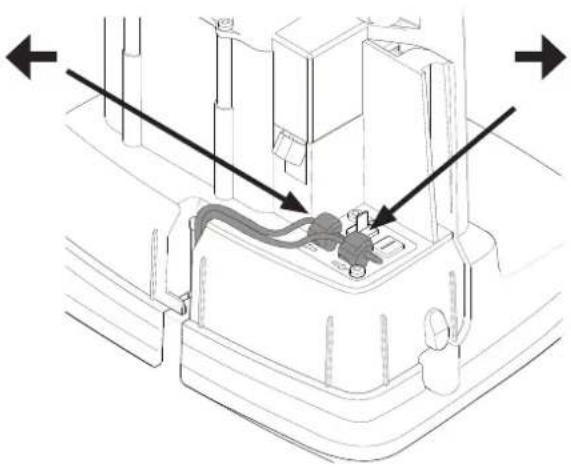
Connect the boundary wire to the charging station as follows:
1 Remove the protective cover on the charging station and thread the wire behind the tabs into the channel at the rear of the charging station.
2 Press the connector onto the metal pins on the charging station (marked with left and right arrows).
NOTE: Make sure the boundary wire to the right of the charging station is connected to the arrow pointing right and the same for the left side.
Installing a Guide Wire
![graph TD A["Thermometer"] --> B["House"] B --> C["Indoor"] C --> D["Plant"] D --> E["Refrigerator"] E --> F["Refrigeration Unit"] F --> G["Refrigeration Room"] G --> H["Refrigeration Floor"] H --> I["Refrigeration Tower"] I --> J["Refrigeration Room"] J --> K["Refrigeration Floor"] K --> L["Refriger…](/content/2026/04/622959/images/eca01240ab83b24f7c107da84a26ed6cb92b82ef9f3d13bd2d55ec3e58cb543c.jpg)
The mower uses the optional guide wire to find its way back to the charging station, but also find hard-to reach areas of the operating area. For example, the guide wire is laid between the charging station and a remote part of the working area or through a narrow passage.
For narrow passages (less than 3 m) or to shorten search times, a guide wire is recommended.
Plan the location of the guide wire before laying out the boundary wire.
Use the same cable roll for both the boundary wire and the guide wire.
The guide wire, like the boundary wire, must be secured to the ground with pegs or buried.
When installing the guide wire on a steep slope, lay the wire at an angle to the slope so it is easier for the mower to follow the guide wire on the slope.
Do not lay the guide wire at sharp angles or the mower will have difficulty following it.
Do not lay the guide wire closer than 30 cm from the boundary wire.
Do not lay the guide wire across the boundary wire.
Run the guide wire straight under the charging plate and then at least 2 m straight out from the front edge of the plate.
Leave as much space as possible to the left of the guide wire (as seen when facing the charging station).
Run the guide wire to the loop on the boundary wire where the guide wire is to be connected.
Cut the boundary wire using the combination pliers.
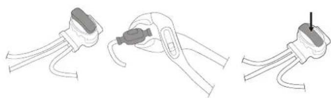
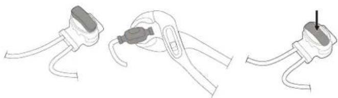
Insert both ends of the boundary wire as well as the end of the guide wire into the splice and guide wire connector. Check that the wires are fully inserted into the splice and guide wire connector so that the ends are visible through the splice and guide wire connector.
Squeeze down the button on top of the splice and guide wire connector fully using a polygrip until you hear a click.
Secure the splice and the boundary and guide wires either using pegs or by burying.
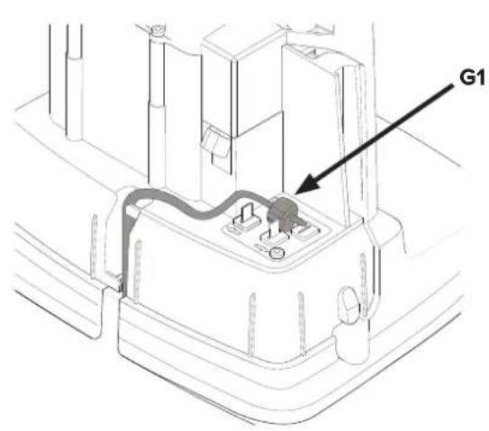
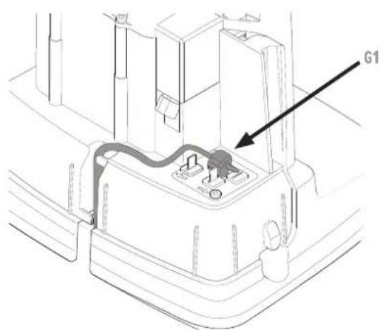
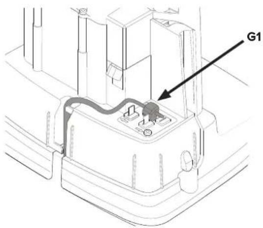
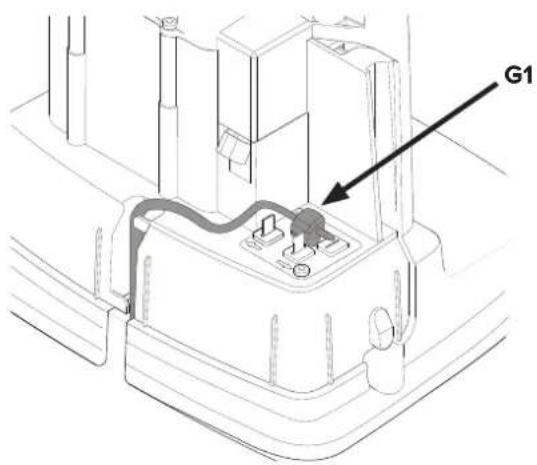
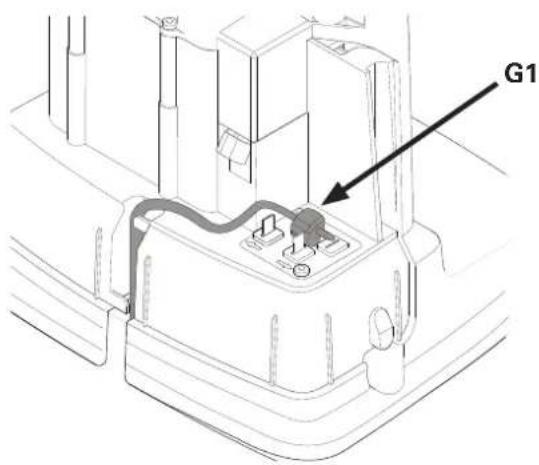
Connect the guide wire to the charging station as follows:
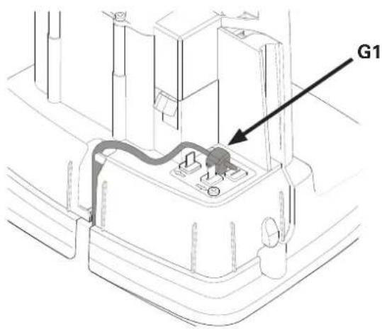
1 Remove the protective cover on the charging station and thread the guide wire behind the tabs into the channel leading to the terminals.
2 Connect the guide wire to the contact pin on the charging station that is labelled G1.
Calibrating and Initial Start Up

Secure the charging station to the ground using the five supplied fixing screws using a 6 mm hex key.
NOTE: Do not make new holes in the charging station base plate. Only the existing holes may be used to secure the base plate to the ground.
NOTE: Do not step or walk on the charging station base plate.
Check the LED indicator on the charging station:
- LED indicator lights up continuously green, if the output voltage of the power supply is available and the boundary wire is not interrupted.
The LED Indicator does not light up when the output voltage of the power supply is not available.
If the indicator LED does not show a solid or green light, see Indicator LEDs on the Charging Station on page 24 for troubleshooting.
Pair the mower with Mobile App as instructed in Pairing Mobile App to Mower on page 19.
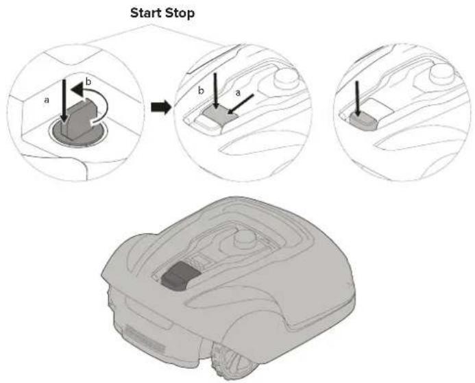
Starting and Stopping the Mower
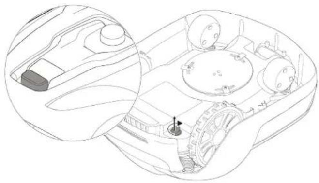
Switching Off the Mower
Adjusting Cutting Height

To start the mower:
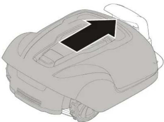
1 Insert the safety key and rotate counter clockwise to position "1".
2 Slide the START button latch backwards.
3 Press down the START button.
To stop the mower:
Press the STOP button on the mower.
Press the STOP button on the mower and remove the safety key.
WARNING! Always remove the safety key when performing maintenance or if the mower must be moved.
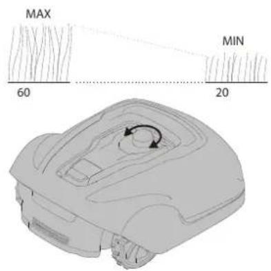
For the first few weeks of mowing, set the cutting height to 60 mm to avoid cutting the boundary wire and guide wire. Lower the setting one step each week thereafter until the desired cutting height is reached.
Turn the cutting height adjustment knob to the required setting. The selected setting is the marking on the body that aligns with the arrow on the knob.
Turn clockwise to increase the cutting height.
Turn anti-clockwise to decrease the cutting height.
The cutting height for the mower can be adjusted between 20 mm and 60 mm.
Lifting and Carrying the Mower
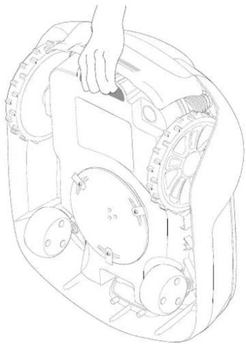
Press the STOP button and remove the safety key before lifting. Always lift the mower using the carrying handle.
Pairing Mobile App to Mower
Download Powerworks GreenGuide from App Store/Google Play and follow the on-screen instructions for how to pair the mower. Have the unique pairing code (found on the quick guide manual) and the mower at hand.
WARNING! Wear protective gloves when handling or working near the sharp blades.
WARNING! Before working on the mower itself, remove the safety key.
WARNING! Before working on the charging station or power supply, remove the plug from the mains.
• Periodically visually inspect the mower and replace worn or damaged parts for safety.
• Inspect that the blades rotate freely
- Keep all nuts, bolts, and screws tight to be sure that the mower is in safe working condition.
- The normal operating life of the blades is 2 to 6 weeks when used at maximum area capacity and longer for smaller areas.
CAUTION: Dull blades result in the grass being cut poorly; requiring more energy and shorter time between battery loadings.
• Clean the mower regularly for best function.
Removing the Body from Chassis

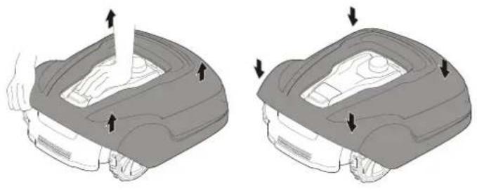
Hold down the mower with one hand and lift firmly at one of the corners of the body and repeat for all four corners, until the body pops loose from the chassis.
Replace the body by aligning the body onto the chassis and press down firmly until you hear the click. Check that the body is firmly attached to the chassis.
Cleaning


WARNING! Press the STOP button and remove the safety key before cleaning.
Clean the exterior of the mower thoroughly using a soft brush, damp cloth, and low pressure water hose, if necessary. Remove the body from the chassis.
Turn the mower on its side and clean the blade area and wheels with a stiff brush or scraper to remove compacted grass clippings.
Replacing Blades

Maintaining the Battery

WARNING! Press the STOP button and remove the safety key before replacing blades and wear protective gloves.
WARNING! Use only GLOBE'S blade: 333092355
CAUTION: Use only original replacement parts.
Replace all three blades and screws as a set at the same time.
Turn the mower upside down.
Loosen the screws using a straight slot or cross tip screwdriver.
Remove the blades and the screws.
Screw in the new blades using new screws.
Check that the blades pivot freely
WARNING! In the event of electrolyte leakage, flush with water/neutralizing agent and seek medical care if electrolyte comes in contact with the eyes.
Only charge the battery in the original charging station. Incorrect use may result in electric shock, overheating, or leakage of corrosive liquid from the battery.
The battery is maintenance-free, but has a limited service life of 2 to 4 years depending on the length of the season and how many hours a day the mower is used.
Replacing the Battery


WARNING! Press the STOP button and remove the safety key before replacing batteries and wear protective gloves.
CAUTION: Use only original replacement parts.
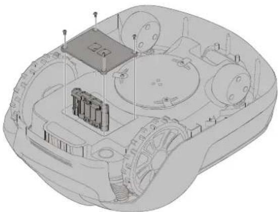
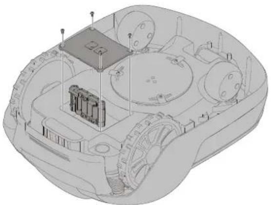
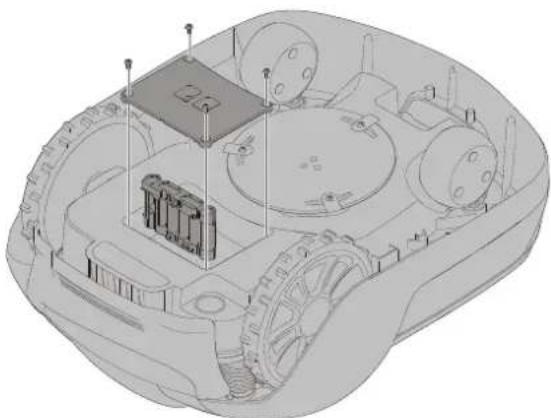
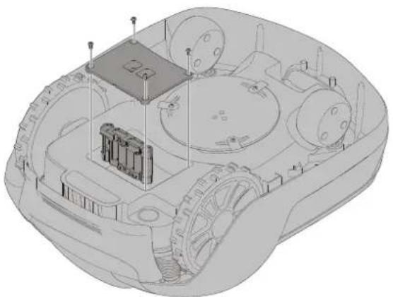
Turn the mower upside down and remove the four Torx T20 screws and remove the battery cover.
Disconnect the battery terminal connector.
Lift the battery straight out.
Insert the new battery in slot 1 (the rear slot).
Connect the battery terminal connector to the new battery.
Put the battery cover back into place and insert and tighten the four Torx T20 screws.

Discard the old battery in accordance with local environmental regulations.
Winter Storage Mower
Always clean the mower before winter storage.
Charge the battery fully before winter storage. If the battery is not fully charged it can be damaged and in certain cases be rendered useless.
CAUTION: If the battery is not fully charged, it can be damaged and in certain cases be rendered useless.
Inspect the condition of wear items; that the blades are sharp and that blades and front wheels turn freely. Correct any deficiencies.
Store the mower in a dry, frost-free environment standing on all four wheels.
Winter storage Charging Station
When possible, disconnect the boundary wire and guide wire from the charging station and store the charging station and power supply indoors.
Leave the boundary wire and the guide wire in the ground, but protect the ends of the wires from dampness by connecting them to an original coupler or putting them in a container with grease.
If it is not possible to store the charging station indoors, the charging station must remain connected to the mains, the boundary wire, and the guide wires.
After Winter Storage
Inspect the mower and charging station contact and charging strips for corrosion, burning, or filth. If the charging or contact strips require cleaning, clean using fine grade emery cloth.
This section also presents some symptoms that can guide you if the mower does not work as expected.
Indicator LEDs on Mower

| LED Status Meaning Action | |||
| 1. Operating (Green) | Flashing Mower stopped with Stop button on mower Press Start on mower for operation | ||
| On Mower in operation mode (charging, parked in Charging station, paused, mowing or searching) | |||
| Off Safety key in in the Disabled position, mower in Error state or mower waiting for PIN code. | |||
| 2. Connectivity (Blue) | Flashing Trying to connect to Internet server | ||
| On Connected to Internet server | |||
| Off Mower not in "Power on mode" | |||
| 3. Security (Yellow) | Flashing PIN code authorization required ... via Mobile App. | ||
| Off No pin required No action required | |||
| 4. Error (Red) | Flashing Mower stopped with error Check the reason for the error and then restart by pressing the Start button on the mower. | ||
Indicator LEDs on Charging Station
| LED Status Meaning Action | |||
| 5. Green On Boundary wire and Charging station OK No action required. | |||
| Blue Flashing Boundary wire broken or not connected Check and repair boundary wire. | |||
| Red | Flashing | Electronic fault in charging station or power supply Unit | Please contact your dealer. |
Symptoms
If your mower does not work as expected, follow the troubleshooting guide below.
| Symptoms Cause Action | ||
| Mower has difficulty docking with charging station | The charging station is on a slope. Place the charging station on a surface that is entirely level. SeeInstalling and connecting the Charging Stationon page 9. | |
| The boundary wire is not laid correctly in relation to the charging station. | Check that the charging station and boundary wire has been correctly installed. SeeInstalling and connecting the Charging Stationon page 9. | |
| Uneven mowing results | The mower works too few hours per day. | Increase the operation time. See the Scheduling function in the Mobile App. |
| The shape of the working area requires manual settings to be made for the mower to find its way to all remote areas. | Adjust lawn coverage to steer the mower to one or more remote areas. SeeSettingsfunction in the Mobile App. | |
| The shape of the working area requires manual settings to be made for the mower to find its way to all remote areas. | Try limiting the operating area or extending the operation time. See the Scheduling function in the Mobile App. | |
| The blades are dull. Replace all the blades and screws so that the rotating parts are balanced. SeeReplacing bladeson page 21. | ||
| Grass collects on the blade disc or around the motor shaft. | Check that the blade disc rotates easily. If not, remove grass and foreign objects. SeeMaintenanceon page 20. | |
| The mower mows for shorter periods than usual between charges | Grass or other foreign object are blocking the blade disc. | Remove grass and foreign objects. SeeMaintenanceon page 20. |
| The battery is worn out. | Replace the battery. SeeReplacing the Batteryon page 22. | |
| Mowing and charging times shorter than usual | The battery is worn out. | Replace the battery. SeeReplacing the Batteryon page 22. |
Breaks in Boundary Wire and Guide Wire
Breaks in the boundary wire and guide wire (if installed) are usually the result of unintentional physical damage.
Inspect the entire boundary wire from the charging station and back.
Inspect the guide wire (if installed) from the charging station to the splice into the boundary wire.
Inspect that all the couplings have been properly squeezed to make connections.
| Optimow 10 Optimow 15 | ||
| Dimensions: | ||
| Height 26 cm 26 cm | ||
| Length 62 cm 62 cm | ||
| Width 50 cm 50 cm | ||
| Weight 11 kg 11 kg | ||
| Electrical system: | ||
| Battery, Special Lithium-Ion battery | 24 V / 2.0 Ah, Part No. 211022355 | 24 V / 2.0 Ah, Part No. 211022355 |
| Power supply 100-240 V/32 V DC 100-240 V/32 V DC | ||
| Low voltage cable length 10 m 10 m | ||
| Mean energy consumption at maximum use 8 kWh/month for a working area of 1,000 m 2 | 10 kWh/month for a working area of 1,500 m 2 | |
| Charge current 1.3 A DC 1.3 A DC | ||
| Average charging time 140 minutes | 70 minutes | |
| Average cutting time | 70 minutes | 70 minutes |
| Noise emissions: *) | ||
| Measured sound power noise level **) | 58 dB (A) | 58 dB (A) |
| Guaranteed sound power noise level | 60 dB (A) | 60 dB (A) |
| Sound pressure noise level ***) | 47 dB (A) | 47 dB (A) |
| Mowing: | ||
| Cutting system | Three pivoted cutting blades | Three pivoted cutting blades |
| Average power consumption during cutting | 25 W ± 20% | 25 W ± 20% |
| Cutting height | 2-6 cm | 2-6 cm |
| Cutting width | 22 cm 22 cm | |
| Narrowest possible passage | 60 cm | 60 cm |
| Maximum angle for cutting area | 35% | 35% |
| Maximum angle for boundary wire | 15% | 15% |
| Maximum length boundary wire | 800 m | 800 m |
| Maximum working capacity | 1,000 m 2 | 1,500 m 2 |
| Recommended area capacity | 0 - 700 m 2 | 500 - 1,200 m 2 |
| IP classification: | ||
| Mower IPX5 IPX5 | ||
| Charging station | IPX2 | IPX2 |
| Power supply IP67 | IP67 | |
*) Noise emissions in the environment measured as sound power (LWA) in conformity with EC directive 2000/14/EC. The guaranteed sound power level includes variation in production as well as variation from the test code with 1-3 dB(A).
The noise emission declarations conforms to EN 50636-2-107:2015
**) uncertainties KWA, 2 dB (A)
***) uncertainties KPA, 2-4 dB (A)
| Radio Frequency Data Sheet | ||
| GPRS(SARA-G350) Short Range Devices (SRD) (Boundary Wire) | ||
| Frequency Band GSM 850 MHz | E-GSM 900 MHzDCS 1800 MHzPCS 1900 MHz | 0~148.5KHz |
| Power Class Class 4(33dBm)for 850/900 bands Class 1(30dBm) for 1800/1900 bands | NA | |

According to the European law 2012/19/EU, electrical and electronic equipment that is no longer usable, and according to the European law 2006/66/EC, defective or used battery packs/batteries, must be collected separately and disposed of in an environmentally correct manner.
The symbol on the mower or its packaging indicates that this product cannot be treated as domestic waste. It should instead be left at a suitable recycling centre to recycle its electronic components and batteries.
The batteries are enclosed in the chassis under the mower. See Replacing the Battery on page 22 for battery removal.
By ensuring that this product is taken care of correctly, you can help to counteract the potential negative impact on the environment and people that can otherwise result through the incorrect waste management of this product.
For more detailed information about recycling this product, contact your municipality, your domestic waste service or the shop from where you purchased the product.

Separate collection of used machine and packaging let you recycle materials and use them again. Use of the recycled materials helps prevent environmental pollution and decreases the requirements for raw materials.
Batteries

At the end of their useful life, discard batteries with a precaution for our environment. The battery contains material that is dangerous to you and the environment. You must remove and discard these materials separately at a equipment that accepts lithium-ion batteries.
GLOBGRO AB, Globe Group Europe guarantees this product's functionality for a period of two years (from date of purchase). The guarantee covers serious faults relating to materials or manufacturing faults. Within the guarantee period, we will replace the product or repair it at no charge if the following terms are met:
- The mower and the charging station may only be used in compliance with the instructions in this operator manual.
- Users or non-authorized third parties must not attempt to repair the product.
Examples of faults which are not included in the guarantee:
• Damage caused by lightning.
- Damage caused by improper battery storage or battery handling.
• Damage caused by using a battery that is not a original battery.
• Damage caused by not using original spare parts and accessories, such as blades and installation material.
• Damage to the loop wire.
The blades are seen as disposable and are not covered by the guarantee.
If a fault occurs with your mower, please contact the dealer for further instructions. Have your receipt and product serial number to hand for quicker assistance.
(Only applicable to European versions)
Name and address of manufacturer:
Manufacturer: GLOBGRO AB, Globe Group Europe
Address: Propellergatan 1, 211 15 Malmö, Sweden
Name and address of the person authorized to compile the technical file:
Name: Peter Söderström
Address: Propellergatan 1, 211 15 Malmö, Sweden
Herewith we declare that the product:
Category: Robotic Lawnmower
Model: P10 / P15
Serial number: See product rating label.
Serial No See product rating label.
• Is in conformity with the provisions of the following other directives:
2014/30/EU
2014/53/EU
2006/42/EC
2011/65/EU & (EU) 2015/863
2014/35/EU
278/2009/EC
- The following (parts/classes of) European harmonized standards have been used:
EN 60335-1, EN 50636-2-107, EN 60335-2-29, EN 62233, EN ISO 3744, EN 55014-1, EN 55014-2, EN 61000-3-2, EN 61000-3-3, EN 61558-1, EN 61558-2-16, EN 62311, EN 301 511, EN 50563, EN 303 413, EN 303 447, Draft EN 301 489-1, Draft EN 301 489-52, Draft EN 301 489-19
IEC 62321-7-2, IEC 62321-4, IEC 62321-5, IEC 62321-6, IEC 62321-7-1, IEC 62321-8, IEC 62321-3-1
Measured sound power level 58 dB(A)
Guaranteed sound power level 60 dB(A)
Conformity assessment method to: Annex V/Directive 2000/14/EC
Notified body involved:
Name: Intertek Testing & Certification Ltd.(Notified body 0359)
Address: Cleeve Road, Leatherhead, Surrey, KT22 7SB United Kingdom
EU-Type Examination Certificate Number: (NB No.) 0004854
Ted Qu Haichao
Quality Director
Malmö, 03. 03. 2019
Ted Qu



Wartung des Akkus


IEC 62321-7-2 :2017, IEC 62321-4 :2013, IEC 62321-5 :2013, IEC 62321-6 :2015, IEC 62321-7-1 :2015, IEC 62321-8 :2017, IEC 62321-3-1:2013




IEC 62321-7-2, IEC 62321-4, IEC 62321-5, IEC 62321-6, IEC 62321-7-1, IEC 62321-8, IEC 62321-3-1
Installazione

Spegnimento Del Tosaerba.

IEC 62321-7-2, IEC 62321-4, IEC 62321-5, IEC 62321-6, IEC 62321-7-1, IEC 62321-8, IEC 62321-3-1
Indirizzo: Cleeve Road, Leatherhead, Surrey, KT22 7SB United Kingdom


FR
Maintenance De La Batterie


IEC 62321-7-2, IEC 62321-4, IEC 62321-5, IEC 62321-6, IEC 62321-7-1, IEC 62321-8, IEC 62321-3-1
Adresse : Cleeve Road, Leatherhead, Surrey, KT22 7SB United Kingdom


Ajustar A Altura De Corte

Remover O Corpo Do Chassis

IEC 62321-7-2, IEC 62321-4, IEC 62321-5, IEC 62321-6, IEC 62321-7-1, IEC 62321-8, IEC 62321-3-1
Morada: Cleeve Road, Leatherhead, Surrey, KT22 7SB United Kingdom


NL

De Accu Onderhouden

NL

IEC 62321-7-2, IEC 62321-4, IEC 62321-5, IEC 62321-6, IEC 62321-7-1, IEC 62321-8, IEC 62321-3-1
Gemeten geluidsdrukniveau 58 dB(A)
Address: Cleeve Road, Leatherhead, Surrey, KT22 7SB United Kingdom

RU




Техобслуживание Акб




Akun Kunnossapito

IEC 62321-7-2, IEC 62321-4, IEC 62321-5, IEC 62321-6, IEC 62321-7-1, IEC 62321-8, IEC 62321-3-1
Mitattu äänenteho 58 dB(A)
Osoite: Cleeve Road, Leatherhead, Surrey, KT22 7SB United Kingdom
Anslut lågspänningskabeln till laddstationen.
SV
SV

Justera Klipphöjden

IEC 62321-7-2, IEC 62321-4, IEC 62321-5, IEC 62321-6, IEC 62321-7-1, IEC 62321-8, IEC 62321-3-1
Adress: Cleeve Road, Leatherhead, Surrey, KT22 7SB United Kingdom


Trykk på STOPP-knappen på gressklipperen og ta ut sikkerhetsnøkkelen før du løfter gressklipperen.
Løft alltid gressklipperen i selve håndtaket.
Paring Av Mobilappen Med Gressklipperen

Vedlikehold Av Batteriet


Brudd I Grense- Og Ledekabel
Brudd I grensekabelen og ledekabelen (hvis installert) skyldes vanligvis at det har oppstått en fysisk skade.
IEC 62321-7-2, IEC 62321-4, IEC 62321-5, IEC 62321-6, IEC 62321-7-1, IEC 62321-8, IEC 62321-3-1
Varslet organ involvert:
Navn: Intertek Testing & Certification Ltd.(Varslet organ 0359)
Adresse: Cleeve Road, Leatherhead, Surrey, KT22 7SB United Kingdom
DA
Placering af ladestation:


DA

Winter storage Charging Station
IEC 62321-7-2, IEC 62321-4, IEC 62321-5, IEC 62321-6, IEC 62321-7-1, IEC 62321-8, IEC 62321-3-1
Målt lydeffektniveau 58 dB(A)
Garanteret lydeffektniveau 60 dB(A)
Overensstemmelsesvurdering i henhold til: Bilag V/direktiv 2000/14/EF
Notificeret myndighed involveret:
Navn: Intertek Testing & Certification Ltd.( Notificeret myndighed 0359)
Adresse: Cleeve Road, Leatherhead, Surrey, KT22 7SB United Kingdom
EU-typeafprøvningsattest, nummer: (NB No.) 0004854
Ted Qu
Ted Qu Haichao
Kvalitetsdirektør
Malmö, 03. 03. 2019


Producent: GLOBGRO AB, Globe Group Europe
Address: Propellergatan 1, 211 15 Malmö, Sweden
IEC 62321-7-2, IEC 62321-4, IEC 62321-5, IEC 62321-6, IEC 62321-7-1, IEC 62321-8, IEC 62321-3-1
Adres: Cleeve Road, Leatherhead, Surrey, KT22 7SB United Kingdom


Údržba Baterie

IEC 62321-7-2, IEC 62321-4, IEC 62321-5, IEC 62321-6, IEC 62321-7-1, IEC 62321-8, IEC 62321-3-1
Adresa: Cleeve Road, Leatherhead, Surrey, KT22 7SB United Kingdom

Pred instaláciou hraničných a vodiacich káblov umiestnite kosačku do nabíjacej stanice.
SK
Údržba Batérie

IEC 62321-7-2, IEC 62321-4, IEC 62321-5, IEC 62321-6, IEC 62321-7-1, IEC 62321-8, IEC 62321-3-1
Address: Cleeve Road, Leatherhead, Surrey, KT22 7SB United Kingdom
1 Snemljiv pokrov
2 Gumb Stop (Ustavi)
3 Gumb Start (Zagon)
4 Indikatorske lučke LED
5 Prilagajanje višine košnje
6 Zadnji kolesi
7 Sprednji kolesi
8 Rezalni disk
9 Pokrov predala za baterijo
10 Nosilni ročaj
11 Varnostni ključ
12 Polnilna postaja


Izklop Kosilnice

Odstranite rezila in vijake.
Privijte nova rezila z novimi vijaki.
Preverite, ali se rezila nemoteno vrtijo.

OPOZORILO! Pritlsnite gumb STOP (USTAVI) In odstranite varnostni ključ, preden zamenjate baterije. Pri tem nosite zaščitne rokavice.
POZOR: Uporabite le originalne nadomestne dele.
IEC 62321-7-2, IEC 62321-4, IEC 62321-5, IEC 62321-6, IEC 62321-7-1, IEC 62321-8, IEC 62321-3-1
Ime: Intertek Testing & Certification Ltd.( Priglašeni organ 0359)
Naslov: Cleeve Road, Leatherhead, Surrey, KT22 7SB United Kingdom
Številka certifikata o pregledu tipa EU: (NB No.) 0004854
Ted Qu
Ted Qu Haichao
Direktor za preverjanje kakovosti
Malmö, 03. 03. 2019
Sljedeće stranice sadrže važne sigurnosne upute i upute za rukovanje.
1 Obavijest na skidljivom poklopcu
2 Gumb za zaustavljanje
3 Gumb za pokretanje
4 LED indikatori
5 Podešavanje visine košnje
6 Stražnji kotači
7 Prednji kotači
8 Disk za noževe
9 Poklopac akumulatora
10 Drška za prenošenje
11 Sigurnosni ključ
12 Stanica za punjenje
13 LED za provjeru rada
14 Priručnik za rukovatelja i brzi vodič
15 Izvor napajanja +
16 Vijci za pričvršćivanje stanice za punjenje (x5)
17 Niskonaponski kabel
18 Žica za petlje za graničnu žicu i žicu vodilicu
19 Kolčići za žicu
20 Dodatni noževi i vijci (x3)
21 Ravnalo (dio koji se otkida s vrha kartonske kutije)
22 Spojnice upletke i žice vodilice)
23 Spojnice za žicu za petlje

Skinite zaštitni poklopac na stanici za punjenje pritiskom na krilca na svakoj strani podnožja i podizanjem poklopca.

Umetnite sigurnosni ključ u donju stranu kosilice i okrenite ga u položaj Omogući (Enable).

Privremeno pričvrstite kraj žice za petlju na kolčić ili neki drugi predmet na stanici za punjenje.
HR
Kad položite svu graničnu žicu i pričvrstite je, montirajte spojnice za žicu za završne petlje na sljedeći način:
1 Otvorite spojnicu za žicu za petlje i stavite žicu u ležište unutar spojnice za žicu za završne petlje.
2 Stisnite spojnice za žicu za završne petlje zajedno papagajkama dok ne čujete klik.
Odrežite sav višak granične žice od 1 do 2 cm iznad svake spojnice.
Ugradnja

Spojite graničnu žicu na stanicu za punjenje na sljedeći način:

Utaknite oba kraja granične žice kao i kraj žice vodilice u spojnicu za upletke i žicu vodilicu. Provjerite jesu li žice do kraja umetnute u spojnicu za upletke i žicu vodilicu tako da se krajevi vide kroz spojnicu za upletke i žicu vodilicu.
Stisnite prema dolje gumb na vrhu spojnice za upletke i žicu vodilicu papagajkama dok ne čujete klik.
Pričvrstite stanicu za punjenje za tlo s pet vijaka isporučenih uz uređaj imbus ključem od 6 mm.
Podešavanje Visine Rezanja

Pokretanje rada kosilice:
Čvrsto držite kosilicu dolje jednom rukom i čvrsto podignite jedan od uglova kućišta i ponovite to za sva četiri ugla dok se kućište uz prigušeni pucanj ne odvoji od šasije.
Održavanje Baterije
UPOZORENJE! Pritlsnite gumb STOP I Izvadite sligurnosni ključ prije zamjene noževa i nosite zaštitne rukavice.
UPOZORENJE! Pritlsnite gumb STOP I Izvadite sigurnosni ključ prije zamjene baterija i nosite zaštitne rukavice.
IEC 62321-7-2, IEC 62321-4, IEC 62321-5, IEC 62321-6, IEC 62321-7-1, IEC 62321-8, IEC 62321-3-1
Adresa: Cleeve Road, Leatherhead, Surrey, KT22 7SB United Kingdom
Broj certifikata EU tipskog ispitivanja: (NB No.) 0004854
Ted Qu
Ted Qu Haichao
Direktor kvalitete
Malmö, 03. 03. 2019
The low voltage cable can cross the operating area if it is stapled down or buried.
HU


IEC 62321-7-2, IEC 62321-4, IEC 62321-5, IEC 62321-6, IEC 62321-7-1, IEC 62321-8, IEC 62321-3-1
Cím: Cleeve Road, Leatherhead, Surrey, KT22 7SB United Kingdom
Connecting the Power Supply.... 10


Fabricant: GLOBGRO AB, Globe Group Europe
Adresa: Propellergatan 1, 211 15 Malmö, Sweden
IEC 62321-7-2, IEC 62321-4, IEC 62321-5, IEC 62321-6, IEC 62321-7-1, IEC 62321-8, IEC 62321-3-1
Adresa: Cleeve Road, Leatherhead, Surrey, KT22 7SB United Kingdom
Număr certificat de examinare de tip EU: (NB No.) 0004854
Ted Qu
RO
Ted Qu Haichao



Separate collection of used machine and packaging let you recycle materials and use them again. Use of the recycled materials helps prevent environmental pollution and decreases the requirements for raw materials.
Batteries

At the end of their useful life, discard batteries with a precaution for our environment. The battery contains material that is dangerous to you and the environment. You must remove and discard these materials separately at a equipment that accepts lithium-ion batteries.
BG
Гаранционни условия
IEC 62321-7-2, IEC 62321-4, IEC 62321-5, IEC 62321-6, IEC 62321-7-1, IEC 62321-8, IEC 62321-3-1





- CONTENTS
- EXPLANATION OF SYMBOLS ON THE MOWER
- READING THE OPERATOR MANUAL
- WEAR PROTECTIVE GLOVES
- IMPORTANT
- READ CAREFULLY BEFORE USE! KEEP FOR FUTURE REFERENCE
- TRAINING
- WARNING! AUTOMATIC LAWNMOWER! KEEP AWAY FROM THE MACHINE! SUPERVISE CHILDREN
- PREPARATION
- GENERAL
- MAINTENANCE AND STORAGE
- OPERATIONAL SAFETY
- PLANNING LAYOUT AND PREPARATION
- CONNECTING THE POWER SUPPLY
- INSTALLING THE BOUNDARY WIRE
- INSTALLING A GUIDE WIRE
- STARTING AND STOPPING THE MOWER
- ADJUSTING CUTTING HEIGHT
- PAIRING MOBILE APP TO MOWER
- REMOVING THE BODY FROM CHASSIS
- CLEANING
- WARNING! PRESS THE STOP BUTTON AND REMOVE THE SAFETY KEY BEFORE CLEANING
- REPLACING THE BATTERY
- WARNING! PRESS THE STOP BUTTON AND REMOVE THE SAFETY KEY BEFORE REPLACING BATTERIES AND WEAR PROTECTIVE GLOVES
- WINTER STORAGE MOWER
- WINTER STORAGE CHARGING STATION
- AFTER WINTER STORAGE
- SYMPTOMS
- BREAKS IN BOUNDARY WIRE AND GUIDE WIRE
- BATTERIES
- INSTALLAZIONE
- REMOVER O CORPO DO CHASSIS
- PARING AV MOBILAPPEN MED GRESSKLIPPEREN
- BRUDD I GRENSE- OG LEDEKABEL
- DA
- ÚDRŽBA BATÉRIE
- UGRADNJA
- UPOZORENJE! PRITLSNITE GUMB STOP I IZVADITE SIGURNOSNI KLJUČ PRIJE ZAMJENE BATERIJA I NOSITE ZAŠTITNE RUKAVICE
- ГАРАНЦИОННИ УСЛОВИЯ
Brand : Powerworks
Model : P10
Category : Lawn mower