GQE15A - Video conferencing system ASUS - Free user manual and instructions
Find the device manual for free GQE15A ASUS in PDF.

User questions about GQE15A ASUS
0 question about this device. Answer the ones you know or ask your own.
Ask a new question about this device
Download the instructions for your Video conferencing system in PDF format for free! Find your manual GQE15A - ASUS and take your electronic device back in hand. On this page are published all the documents necessary for the use of your device. GQE15A by ASUS.
USER MANUAL GQE15A ASUS
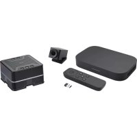
ASUS-Google Meet hardware kit GQE15A
User Guide
CA19867
Revised Edition V2
February 2022
COPYRIGHT INFORMATION
No part of this manual, including the products and software described in it, may be reproduced, transmitted, transcribed, stored in a retrieval system, or translated into any language in any form or by any means, except documentation kept by the purchaser for backup purposes, without the express written permission of ASUSTeK COMPUTER INC. ("ASUS").
ASUS PROVIDES THIS MANUAL "AS IS" WITHOUT WARRANTY OF ANY KIND, EITHER EXPRESS OR IMPLIED, INCLUDING BUT NOT LIMITED TO THE IMPLIED WARRANTIES OR CONDITIONS OF MERCHANTABILITY OR FITNESS FOR A PARTICULAR PURPOSE. IN NO EVENT SHALL ASUS, ITS DIRECTORS, OFFICERS, EMPLOYEES OR AGENTS BE LIABLE FOR ANY INDIRECT, SPECIAL, INCIDENTAL, OR CONSEQUENTIAL DAMAGES (INCLUDING DAMAGES FOR LOSS OF PROFITS, LOSS OF BUSINESS, LOSS OF USE OR DATA, INTERRUPTION OF BUSINESS AND THE LIKE), EVEN IF ASUS HAS BEEN ADVISED OF THE POSSIBILITY OF SUCH DAMAGES ARISING FROM ANY DEFECT OR ERROR IN THIS MANUAL OR PRODUCT.
Products and corporate names appearing in this manual may or may not be registered trademarks or copyrights of their respective companies, and are used only for identification or explanation and to the owners' benefit, without intent to infringe.
SPECIFICATIONS AND INFORMATION CONTAINED IN THIS MANUAL ARE FURNISHED FOR INFORMATIONAL USE ONLY, AND ARE SUBJECT TO CHANGE AT ANY TIME WITHOUT NOTICE, AND SHOULD NOT BE CONSTRUED AS A COMMITMENT BY ASUS. ASUS ASSUMES NO RESPONSIBILITY OR LIABILITY FOR ANY ERRORS OR INACCURACIES THAT MAY APPEAR IN THIS MANUAL, INCLUDING THE PRODUCTS AND SOFTWARE DESCRIBED IN IT.
Copyright © 2022 ASUSTeK COMPUTER INC. All Rights Reserved.
LIMITATION OF LIABILITY
Circumstances may arise where because of a default on ASUS' part or other liability, you are entitled to recover damages from ASUS. In each such instance, regardless of the basis on which you are entitled to claim damages from ASUS, ASUS is liable for no more than damages for bodily injury (including death) and damage to real property and tangible personal property; or any other actual and direct damages resulted from omission or failure of performing legal duties under this Warranty Statement, up to the listed contract price of each product.
ASUS will only be responsible for or indemnify you for loss, damages or claims based in contract, tort or infringement under this Warranty Statement.
This limit also applies to ASUS' suppliers and its reseller. It is the maximum for which ASUS, its suppliers, and your reseller are collectively responsible.
UNDER NO CIRCUMSTANCES IS ASUS LIABLE FOR ANY OF THE FOLLOWING: (1) THIRD-PARTY CLAIMS AGAINST YOU FOR DAMAGES; (2) LOSS OF, OR DAMAGE TO, YOUR RECORDS OR DATA; OR (3) SPECIAL, INCIDENTAL, OR INDIRECT DAMAGES OR FOR ANY ECONOMIC CONSEQUENTIAL DAMAGES (INCLUDING LOST PROFITS OR SAVINGS), EVEN IF ASUS, ITS SUPPLIERS OR YOUR RESELLER IS INFORMED OF THEIR POSSIBILITY.
SERVICE AND SUPPORT
Visit our multi-language web site at https://www.asus.com/support/
Contents
About this user guide....6
Package contents 7
Getting to know your Meet Compute System
Features....12
Rear view....12
Left side view....14
Right side view....14
Bottom view....15
Using your Meet hardware kit
Getting started 18
Connect a display panel to your Meet Compute System 18
Connect the speakermic....19
Connect the camera....20
Connect the touchscreen....21
Connect the remote control dongle to your Meet Compute System......24
Connect the AC power adapter to your Meet Compute System....25
Turn on your Meet Compute System....27
Configuring your ASUS - Google Meet hardware kit
Before you begin using your device for video conferencing....30
Setup requirements ....30
Setup your system 33
Enroll your device ....44
Manage devices and rooms....47
Troubleshooting
Fix a problem....50
Help and support....50
Appendix
Safety information....52
Setting up your system....52
Care during use....53
Regulatory notices 55
About this user guide
This user guide provides information about the hardware and software features of your Meet hardware kit, organized through the following chapters:
Chapter 1: Getting to know your Meet Compute System
This chapter details the hardware components of your Meet Compute System.
Chapter 2: Using your Meet hardware kit
This chapter provides you with information on using your Meet hardware kit.
Chapter 3: Configuring your ASUS - Google Meet hardware kit
This chapter provides you with information on setting up your ASUS - Google Meet hardware kit for video conferencing.
Troubleshooting
This section includes instructions on how to fix a problem that you may encounter when using your Meet hardware kit.
Appendix
This section includes notices and safety statements for your Meet Compute System.
Conventions used in this user guide
To highlight key information in this user guide, some text are presented as follows:
IMPORTANT! This message contains vital information that must be followed to complete a task.
WARNING! This message contains important information that must be followed to keep you safe while performing certain tasks and prevent damage to your device, data and components.
NOTE: This message contains additional information that can help complete tasks.
Package contents
Your Meet hardware kit package contains the items detailed below. You can also refer to the Meet hardware kit peripheral table for details on the peripheral items included in the different kits.
Meet Compute System items:
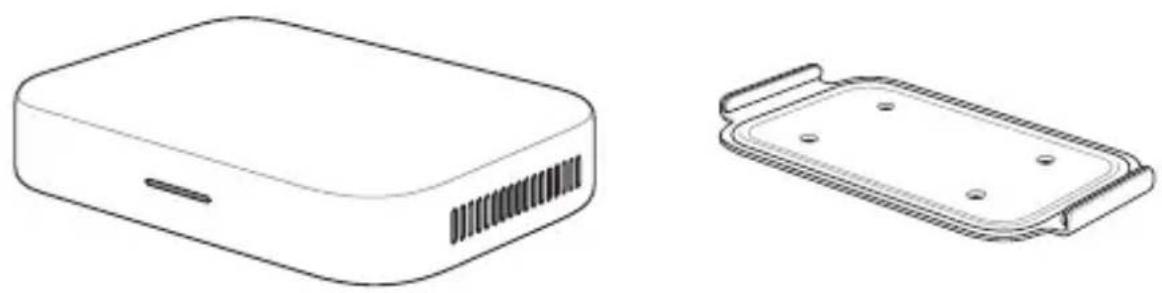
natural_image
Technical line drawings of two electronic devices: a rectangular box with ventilation slots and a rectangular housing with mounting holes (no text or symbols)Meet Compute System Wall mounting plate
natural_image
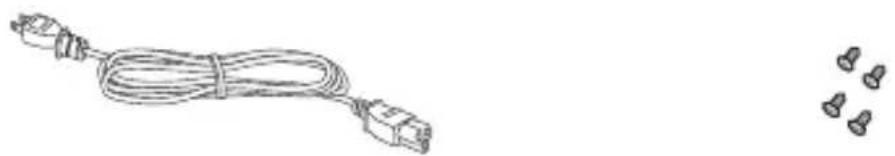
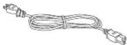
Line drawing of a cable with connectors and two separate screw-like components (no text or symbols)Power cable* Wall mounting plate screw set
natural_image
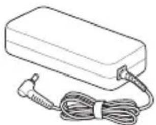
Line drawing of a rectangular electronic device with a coiled cable and terminal connector (no text or symbols)AC power adapter*
natural_image
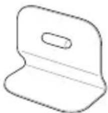
Simple line drawing of a mechanical part with a slot (no text or symbols)Standing mount
text_image
IN SEARCH OF INCREODIBLE 100.00 750.00Technical documentation
Peripheral items:
natural_image
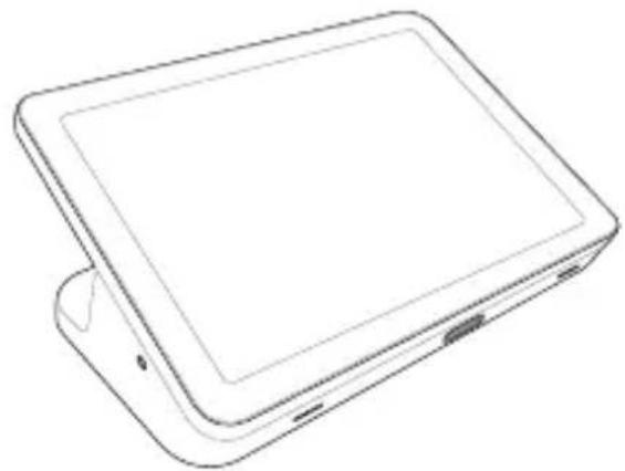
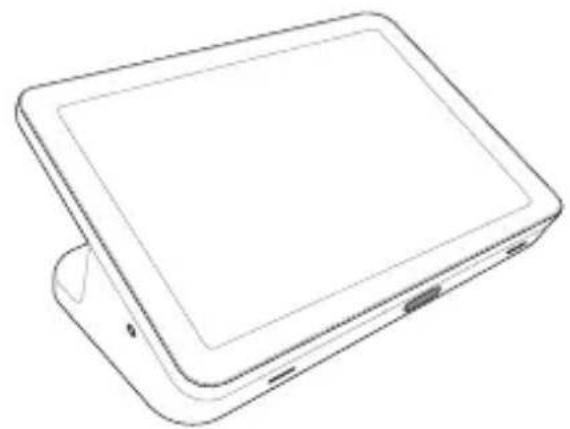
Line drawing of a tablet device with a flat screen and side buttons (no text or symbols)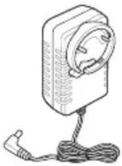
natural_image
Line drawing of a handheld device with a circular lens and cable (no text or symbols)Touchscreen Touchscreen power adapter
natural_image
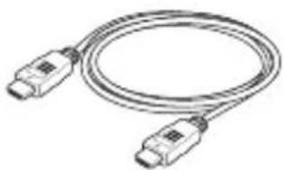
Coiled cable with two connectors (no text or symbols visible)Touchscreen HDMI™ cable
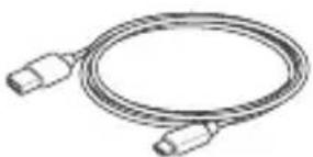
natural_image
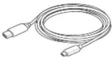
Line drawing of a coiled cable with two connectors (no text or symbols)Touchscreen USB data cable
natural_image
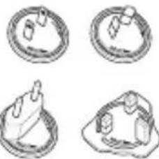
Four circular diagrams showing different types of objects or devices, possibly mechanical parts or installations (no text or symbols)Touchscreen adapter plug heads*
natural_image
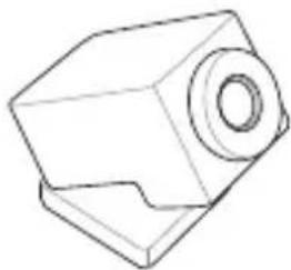
Technical line drawing of a mechanical component with a cylindrical top and flange (no text or symbols)Camera Speakermic
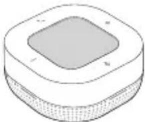
natural_image
Isometric illustration of a square-shaped device with a central square and textured base (no text or symbols)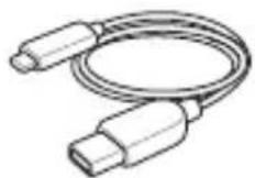
Camera USB cable (Type-A to USB Type-C®)
natural_image
Line drawing of a flexible cable with two connectors (no text or symbols)Speakermic USB cable (Type-A to USB Type-C®)

Remote Control

USB dongle
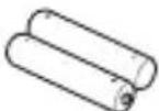
Batteries
Meet hardware kit peripheral table
| Meet hardware kit | |||
| Small/Medium Room Kit | Large Room Kit Starter Kit | ||
| Meet Compute System | V V V | ||
| Speakermic V V V | |||
| Camera V - V | |||
| Touchscreen control panel | V V - | ||
| Remote control -- V | |||
NOTE:
- If the device or its components fail or malfunction during normal and proper use within the warranty period, bring the warranty card to the ASUS Service Center for replacement of the defective components.
- The bundled accessories may vary depending on your model.
- For details on bundled accessories, refer to their respective user manuals.
1
Getting to know your Meet Compute System
Features
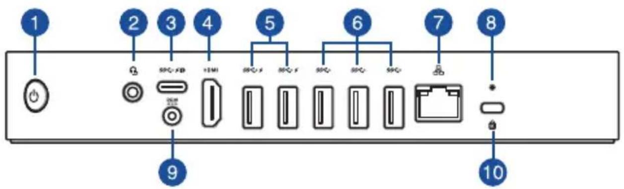
Rear view
text_image
1 2 3 4 5 6 7 8 9 10

Power button
The power button allows you to turn the Meet Compute System on or off. You can use the power button to put your Meet Compute System to sleep mode or press it for four (4) seconds to force shutdown your Meet Compute System.


Headphone/Headset/Microphone jack
This port allows you to connect amplified speakers or headphones. You can also use this port to connect your headset or an external microphone.


USB 3.2 Gen 1 Type-C®/DisplayPort combo port
This USB Type-C® (Universal Serial Bus) port provides a transfer rate of up to 5 Gbit/s; supports DisplayPort 1.2 (3840 x 2160) at 60Hz with 24-bit color; and supports Power Delivery at 5v, 3A. Use a USB Type-C® adapter to connect your Meet Compute System to an external display.

HDMI
HDMI™ port
The HDMI™ (High Definition Multimedia Interface) port supports a Full-HD device, such as an LCD TV or monitor, to allow viewing on a larger external display.


USB 3.2 Gen 1 port
The USB 3.2 Gen 1 (Universal Serial Bus) port provides a transfer rate up to 5 Gbit/s. This port also supports the Battery Charging 1.2 technology that allows you to charge your USB devices.
NOTE: Battery Charging 1.2 technology is only available on selected models, and provides a maximum of 5V / 1.5A output.


USB 3.2 Gen 1 port
The USB 3.2 Gen 1 (Universal Serial Bus) port provides a transfer rate up to 5 Gbit/s.


LAN port
The 8-pin RJ-45 LAN port supports a standard Ethernet cable for connection to a local network.


Reset button
The reset button allows you to reset the Meet Compute System.


Power input
The supplied power adapter converts AC power to DC power for use with this jack. Power supplied through this jack supplies power to the Meet Compute System. To prevent damage to the Meet Compute System, always use the supplied power adapter.
WARNING! The power adapter may become warm to hot when in use. Do not cover the adapter and keep it away from your body.


Kensington security slot
The Kensington security slot allows you to secure your Meet Compute System using Kensington® security products.
Left side view

natural_image
Pure diagram of a rectangular container with internal rows, no text or symbols present1 Air vents (intake vent)
The air vents allow cooler air to enter your Meet Compute System chassis.
IMPORTANT! For an optimum heat dissipation and air ventilation, ensure that the air vents are free from obstructions.
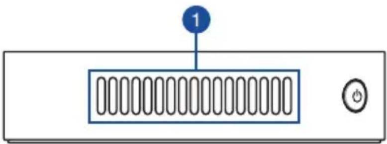
Right side view
natural_image
Front view of a server rack with a button and indicator light (no text or symbols)1 Air vents (exhaust vent)
The air vents allow your Meet Compute System chassis to expel hot air out.
IMPORTANT! For an optimum heat dissipation and air ventilation, ensure that the air vents are free from obstructions.
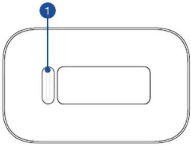
Bottom view
flowchart
graph TD
    A["1"] --> B["Process Step"]

Mount pad slot
The mount slot is used to attach the Meet Compute System to the standing mount.
2
Using your Meet hardware kit
Getting started
Connect a display panel to your Meet Compute System
You can connect a display panel or projector that has the following connectors:
•HDMI™connector
•DisplayPort(USBType-C ^® )
• DVI connector (used with an HDMI™–DVI adapter)
NOTE:
- The HDMI™–DVI adapter is purchased separately.
- The USB Type-C®-HDMI™ cable is purchased separately.
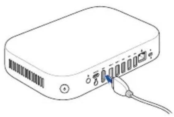
To connect a display panel to your Meet Compute System:
Connect a display cable either to the HDMI™ port or the USB Type-C® DisplayPort.
Connect display via HDMI™ port Connect display via USB Type-C® DisplayPort
natural_image
Line drawing of a rectangular electronic device with ports and cables, no text or symbols present
natural_image
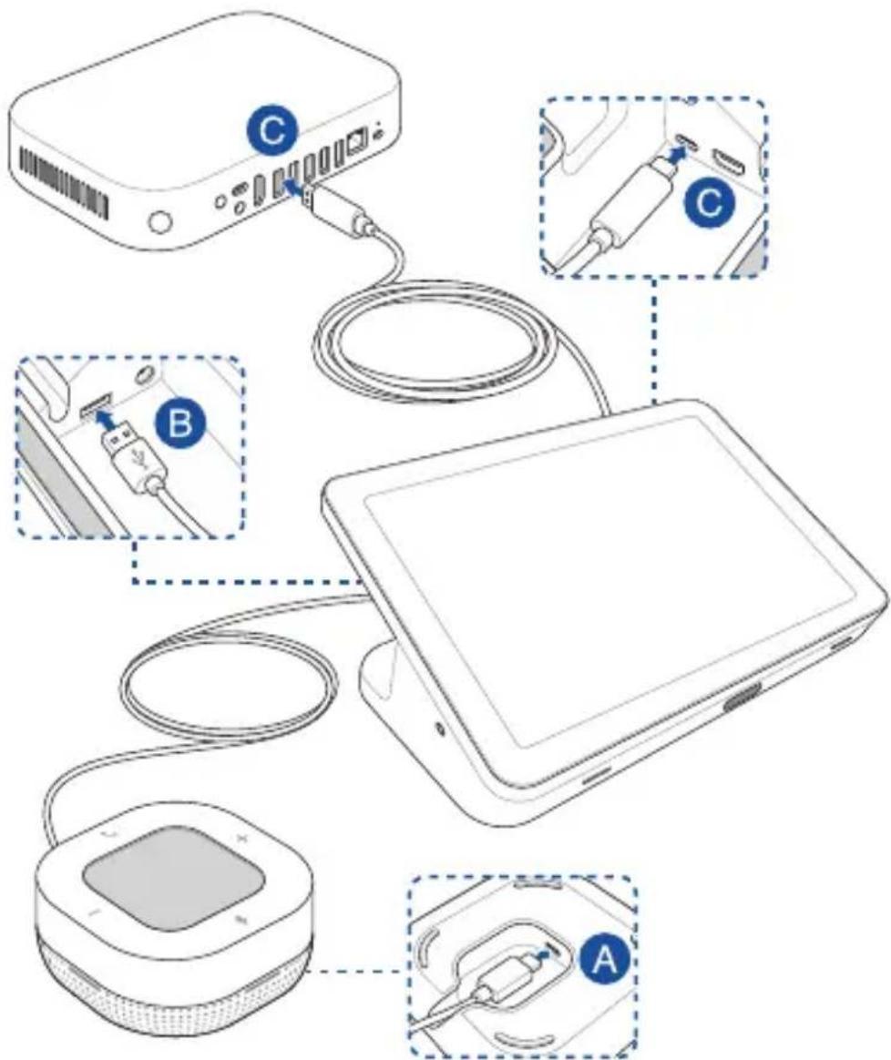
Line drawing of a rectangular electronic device with ports and a cable (no text or symbols)Connect the speakermic
To connect the speakermic to your Meet Compute System:
A. Connect the USB Type-C® end of the speakermic USB data cable to the data USB port on your speakermic.
B. Connect the other end of the USB data cable to USB Type-A port located at the bottom of touchscreen.
C. Connect the touchscreen to your Meet Compute System. See the section Connect the touchscreen for more details.
NOTE: For more information on the recommended USB 3.2 Gen 1 port to connect the touchscreen to, refer to the section Connect your cables.
text_image
Diagram showing connected devices with labeled components A, B, and C, illustrating cable connections and connectivity.Connect the camera
Connect the camera to a USB 3.2 Gen 1 port on the rear of your Meet Compute System.
NOTE: For more information on the recommended USB 3.2 Gen 1 port to connect the camera to, refer to the section Connect your cables.

natural_image
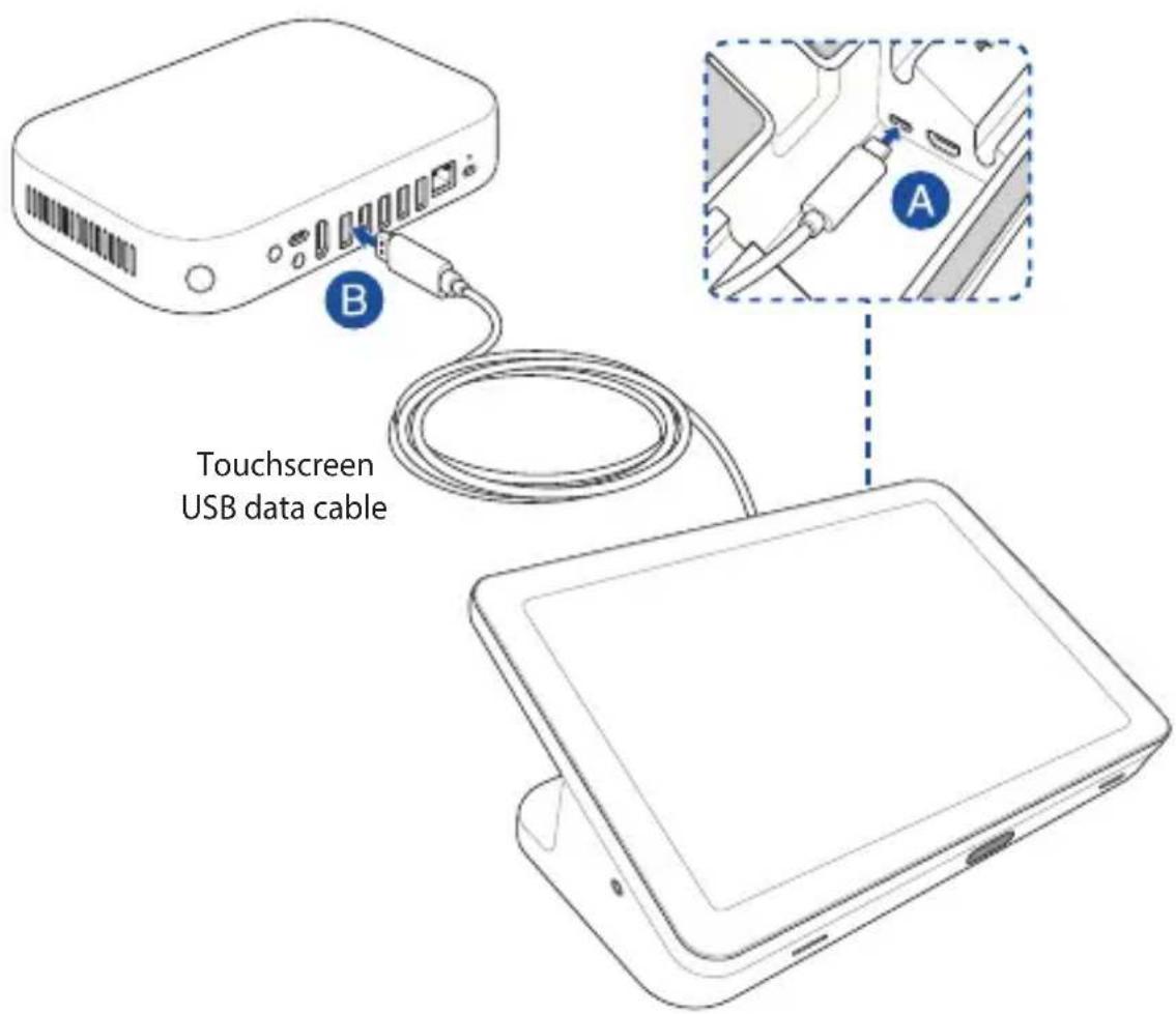
Line drawing of a portable electronic device with cable and connector (no text or symbols)Connect the touchscreen
To connect the touchscreen to your Meet Compute System
A. Connect the USB Type-C ^® end of the touchscreen USB data cable to the data USB port on your touchscreen.
B. Connect the touchscreen to a USB 3.2 Gen 1 port on the rear of your Meet Compute System. Ensure to connect the USB 3.2 Gen 1 connector to connect to your Meet Compute System.
NOTE: For more information on the recommended USB 3.2 Gen 1 port to connect the touchscreen to, refer to the section Connect your cables.
text_image
B Touchscreen USB data cable ATo connect the AC power adapter to your touchscreen
A. Connect the touchscreen power adapter to the power input jack on your touchscreen.
B. Attach the appropriate adapter plug head to the adapter, then plug the AC power adapter into a 100V\~240V power source.
NOTE: For more information on attaching the adapter plug head to the adapter, refer to the user guide bundled with the touchscreen.

text_image
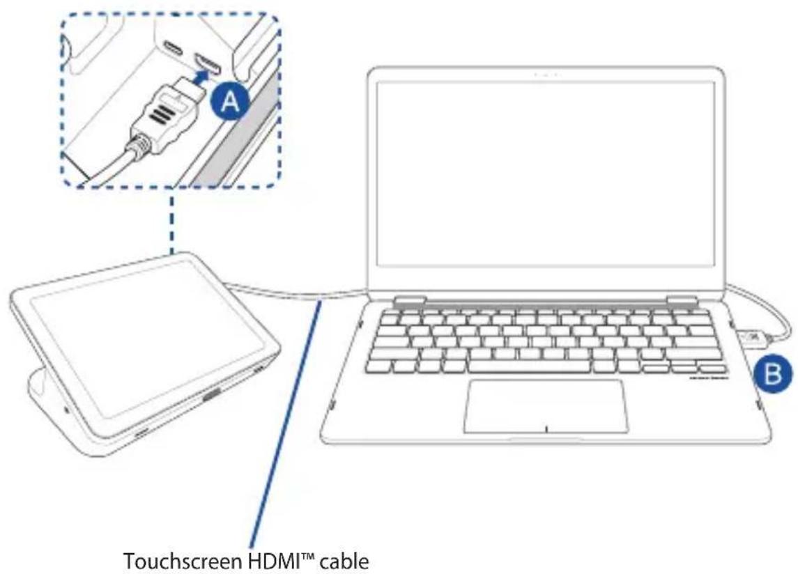
Diagram showing a device connected to a wall-mounted power outlet, with labeled components A and B.To connect the touchscreen for local presentations (optional)
NOTE: Ensure to use the Touchscreen HDMI™ cable.
A. Connect the Touchscreen HDMI™ cable to the HDMI™ port on your touchscreen.
B. Connect the touchscreen to a device's (such as a laptop) HDMI™ out port for local presentations.
WARNING! Do not connect the HDMI™ cable to your Meet Compute System.
text_image
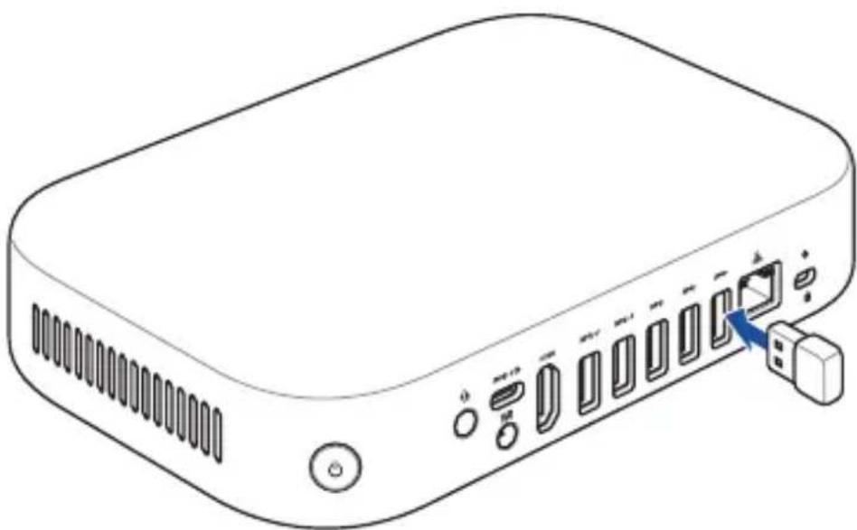
Touchscreen HDMI™ cableConnect the remote control dongle to your Meet Compute System
Connect the remote control USB dongle to a USB 3.2 Gen 1 port on the rear of your Meet Compute System.
natural_image
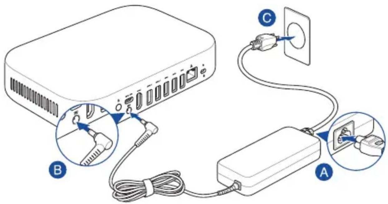
Line drawing of a rectangular electronic device with ports and connectors, showing no text or symbolsConnect the AC power adapter to your Meet Compute System
To connect the AC power adapter to your Meet Compute System:
A. Connect the AC power cord to the AC/DC adapter.
B. Connect the DC power connector to your Meet Compute System's power (DC) input jack.
C. Plug the AC power cord into a 100V\~240V power source.
NOTE: The power adapter may vary in appearance, depending on model and region.
text_image
Diagram showing cable connection to a device with labeled components A, B, and C, including plug connectors and power outlet.IMPORTANT!
- We strongly recommend that you use only the AC power adapter that came with your Meet Compute System.
- We strongly recommend that you use a grounded wall socket while using your Meet Compute System.
- The socket outlet must be easily accessible and near your Meet Compute System.
- To disconnect your Meet Compute System from its main power supply, unplug your Meet Compute System from the power socket.
NOTE:
Refer to the following information on the adapter:
90W Power adapter
- Input voltage: 100-240 Vac
- Input frequency: 50-60 Hz
• Rating output current: 4.62 A (90W)
• Rating output voltage: 19.5 V
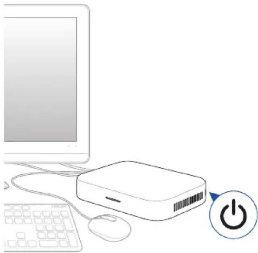
Turn on your Meet Compute System
Press the power button to turn on your Meet Compute System.
IMPORTANT! Ensure that all peripherals (speakermic, camera, touchscreen) and AC power adapter are connected properly before you turn on your Meet Compute System.
natural_image
Illustration of a desktop computer setup with monitor, keyboard, mouse, and power button (no text or symbols)3
Configuring your ASUS - Google Meet hardware kit
Before you begin using your device for video conferencing
Setup requirements
Room size and setup
Your Meet hardware kit system is designed for a conference room of up to 20 persons. We recommend a room that contains either a long table with the monitor at one end (optimal), or a round table. We do not recommend using Meet Compute System with rooms set up in a classroom style.
The room must have the following:
• Live Ethernet port (for wired network connections)
- AC power outlet
Network requirements
Your Meet Compute System device works with both wired and wireless networks. The network requirements are the same as those for Google Meet. In addition, we recommend a minimum bandwidth of 1 Mbps or 2 Mbps (up/down) for group video conferencing. Please refer to the following additional bandwidth requirements for video quality.
NOTE: Although you can use your Meet Compute System device over a wireless network connection, we recommend using a wired network connection for best sound and video quality.
For HD video quality
- Latency should be less than 50 ms when pinging Google's public DNS server at 8.8.8.8.
- Outbound signals from a participant in all situations must meet a 3.2 Mbps bandwidth requirement.
- Inbound signals depend on the number of participants:
- 2.6 Mbps with 2 participants
- 3.2 Mbps with 5 participants
- 4.0 Mbps with 10 participants
For Standard definition (SD) video quality
- Latency should be less than 100 ms when pinging Google's public DNS server at 8.8.8.8.
- Outbound signals from a participant in all situations must meet a 1 Mbps bandwidth requirement.
- Inbound signals depend on the number of participants:
- 1 Mbps with 2 participants
- 1.5 Mbps with 5 participants
- 2 Mbps with 10 participants
Space requirements
- For the Meet Compute System device, you must have a 40 mm x 250 mm x 180 mm / 1.57 in. x 9.84 in. x 7.08 in. space available to mount the device or place it on a table.
- For the speakermic, you must have at least a 55 mm x 140 mm x 150 mm / 2.17 in. x 5.51 in. x 5.91 in. (H x W x L) space available to place the unit on the table or mount it on the wall.
- For the touchscreen control panel, you must have a 250 mm x 200 mm x 300 mm / 9.84 in. x 7.87 in. x 11.81 in. (H x W x L) space available to place it on a table
- The universal hook mount on the camera fits the width on most standard monitors.
Display requirements and placement
Your Meet Compute System work with LCD, LED, plasma, and projector-type monitors and televisions. The display must have an HDMI ^™ or DisplayPort input.
You can place the display on a table against one wall, or mount the display on a wall or ceiling for a projector unit. Note that if you mount the display, you may need to drill holes and conceal cables. If you have an existing video conferencing system in the room, you may be able to repurpose the existing setup for your Meet Compute System.
Speakermic placement
The optimal speakermic placement is up to 1.5 meters from all participants, but may also depend on the size and layout of the conference room:
- For rooms where participants sit at one end of the room facing the display, we recommend placing the speakermic at the end of the table closest to the Meet Compute System and the display.
- In larger rooms where meeting participants would be seated beyond the optimal range of a single Speakermic it is possible to daisy chain up to 4 additional speakermics (placed between 1.5m and 2m of each other) using an ethernet cable. Additional Speakermics do not require their own power source as they support POE (Power over Ethernet).
Connectors and accessories
Depending on your setup, you may need the following:
- CAT5e Ethernet cable for wired network connection
- Meet Compute System wall mount for wall mounting (included)
- USB extension cable for camera for distances exceeding 5 feet (one cable included), if you require extension cables for both the camera and the speakermic, please refer to the Google Meet Qualified Peripherals List webpage.
- USB extension cable for speakermic for distances exceeding 3 feet (one cable included)
NOTE: If you need extension cables for both the camera and the speakermic, you can purchase a second one separately.
- Cable concealers, if needed for wall mounting
NOTE: The cable concealers for wall mounting and CAT5e Ethernet cable are not included in the package and must be purchased separately.
IMPORTANT! The included cable for the camera is 5 feet long, and the included cable for the speakermic is 3 feet long. If your setup of the display, Meet Compute System, and peripherals requires longer distances, you may need to purchase additional USB extension cables.
Setup your system
You can mount your Meet Compute System to the wall mounting plate or mount the Meet Compute System to the standing mount.
WARNING!
- Pulling or pushing on the Meet Compute System may cause the device to fall.
- Do not install your mount kit while your Meet Compute System is turned on. This may cause personal injuries or damage the system.
NOTE: The bundled items may vary between models. The wall mounting plate and standing mount may not be included.
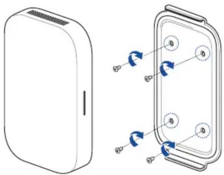
Using the Wall mount
Use the wall mount plate to attach the Meet Compute System to a wall. Please follow the steps below to install the wall mount and Meet Compute System:
IMPORTANT! The equipment should not be mounted higher than 2 m from the floor or should not be mounted higher than 75 cm from a flat surface.
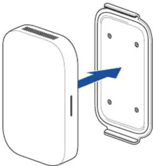
- Secure the wall mount to a wall using the four (4) screws.
NOTE: The screws are self tapping M3.5 24 mm long, flat countersunk head type screws.
text_image
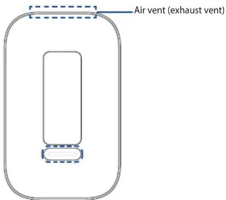
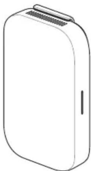
Diagram showing a device with labeled components and directional arrows indicating rotation or movement in a device panel.- Locate the mount pad slot on the bottom of your device and orientate it as shown in the illustration below so that the exhaust air vents face upwards.
NOTE: Please refer to Chapter 1 Getting to know your Meet Compute System for more information on the location of the exhaust air vents.
text_image
Air vent (exhaust vent)- Your device will be held in place magnetically to the standing mount. Please ensure the mount pad slots are aligned with the wall mount before placing the device onto the wall mount plate.
NOTE: Please refer to Chapter 1 Getting to know your Meet Compute System for more information on the location of the mount pad slots.
natural_image
Diagram showing a device connected to a rectangular panel with a blue arrow indicating direction (no text or symbols present)- Manually adjust your device if needed for a more secure fit.
natural_image
Line drawing of a rectangular electronic device with a flat top and side slot (no text or symbols)Using the standing mount
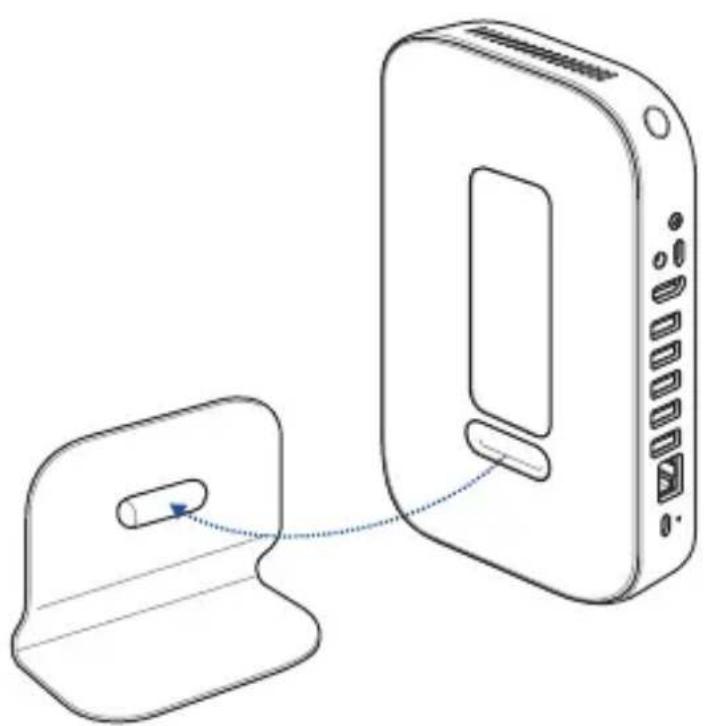
To attach your Meet Compute System to the bundled standing mount, please follow the steps below:
- Locate the mount pad slot on the bottom of your device and orientate it as shown in the illustration below so that the exhaust air vents faces upwards.
NOTE: Please refer to Chapter 1 Getting to know your Meet Compute System for more information on the location of the exhaust air vents.
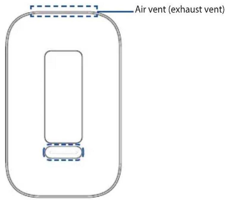
text_image
Air vent (exhaust vent)- Align your device's mount pad slot to the standing mount, then bring the device closer to the mount. Your device will be magnetized and attach onto the standing mount.
natural_image
Diagram showing a device connected to a rectangular device with ports and a small component, no text or symbols present.- Manually adjust your device if needed for a more secure fit.

natural_image
Line drawing of a wireless router device with ports and ventilation slots (no text or symbols)Place your camera
You may install your camera below or on top of the display depending on the screen height.
NOTE: Keep the camera as close to eye level as possible.
Recommended meeting room configuration 1
System setup
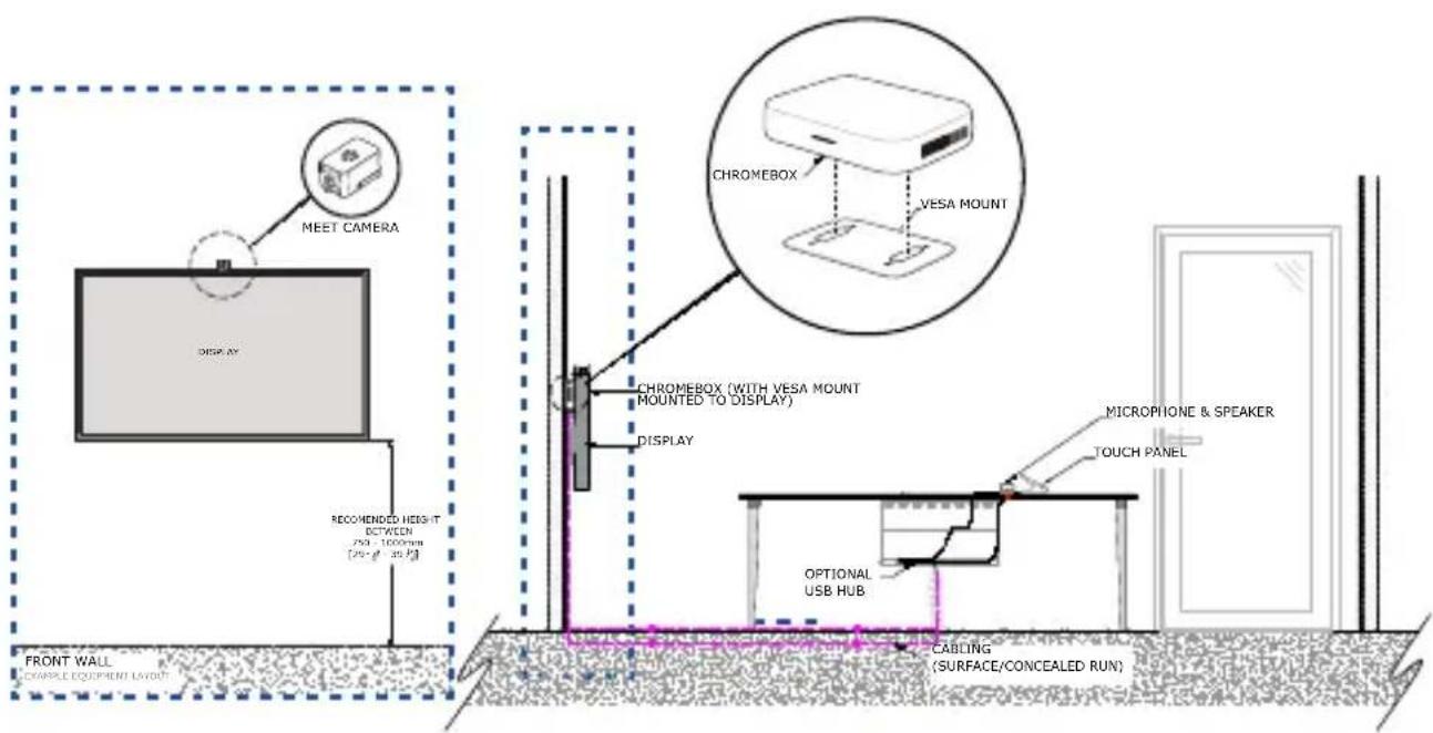
text_image
MEET CAMERA DISPLAY RECOMMENDED HEIGHT BETWEEN 250 - 1000mm [250 - 80 - 350] CHROMEROX VESA MOUNT CHROMEROX (WITH VESA MOUNT MOUNTED TO DISPLAY) DISPLAY MICROPHONE & SPEAKER TOUCH PANEL OPTIONAL USB HUB CABLEING (SURFACE/CONCEALED RUN) FRONT WALL COMPLETE EQUIPMENT LAYOUTRoom layout example
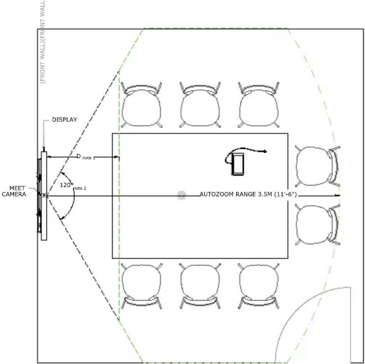
text_image
(FRONT WALL)(FRONT WALL) DISPLAY D note 1 120° note 2 MEET CAMERA AUTOZOOM RANGE 3.5M (11'-6")Recommended meeting room configuration 2
System setup
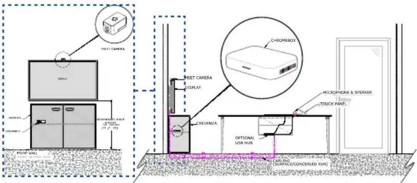
text_image
MEET CAMERA DISPLAY CRENDATA CHROMBOX SPRINGHOLD HIGH 40" THO 5mm (15" x2" 20" FRONT WALL BEANS FOR SHEET LANE MEET CAMERA DISPLAY CRENDATA CHROMBOX CHROMEBOX MICROPHONE & SPEAKER TOUCH PANEL OPTIONAL USB HUB CARLING (SURFACE/CONCEALED RUN)NOTE: Ensure that the credenza you wish to install your Meet Compute System to is not tightly packed with cables or other objects which may obstruct the air vents of your Meet Compute System, and has openings to allow proper air flow.
Room layout example
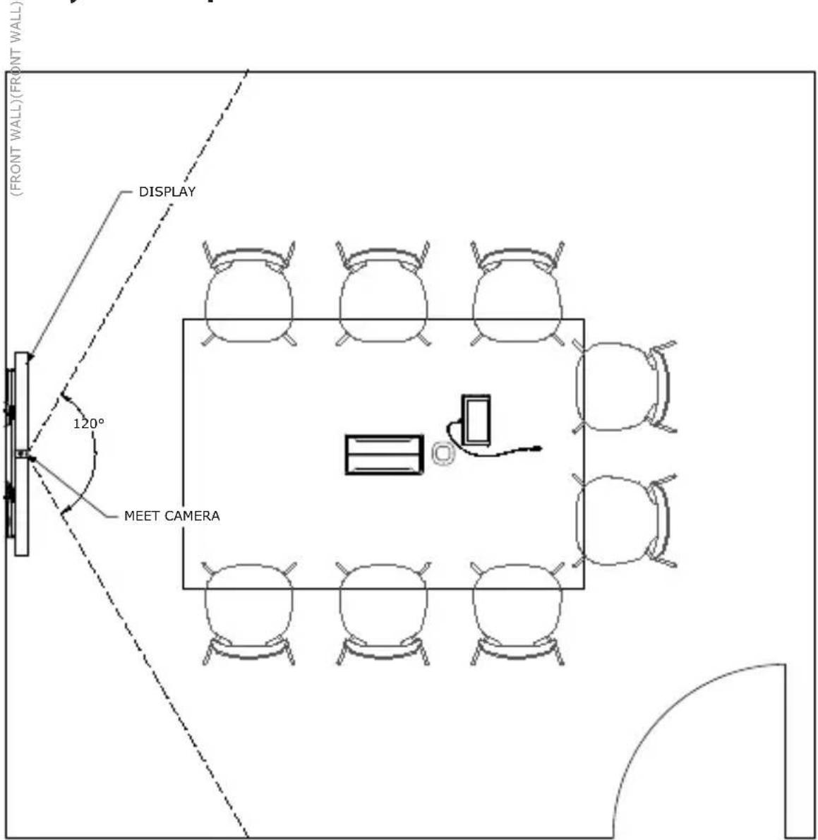
text_image
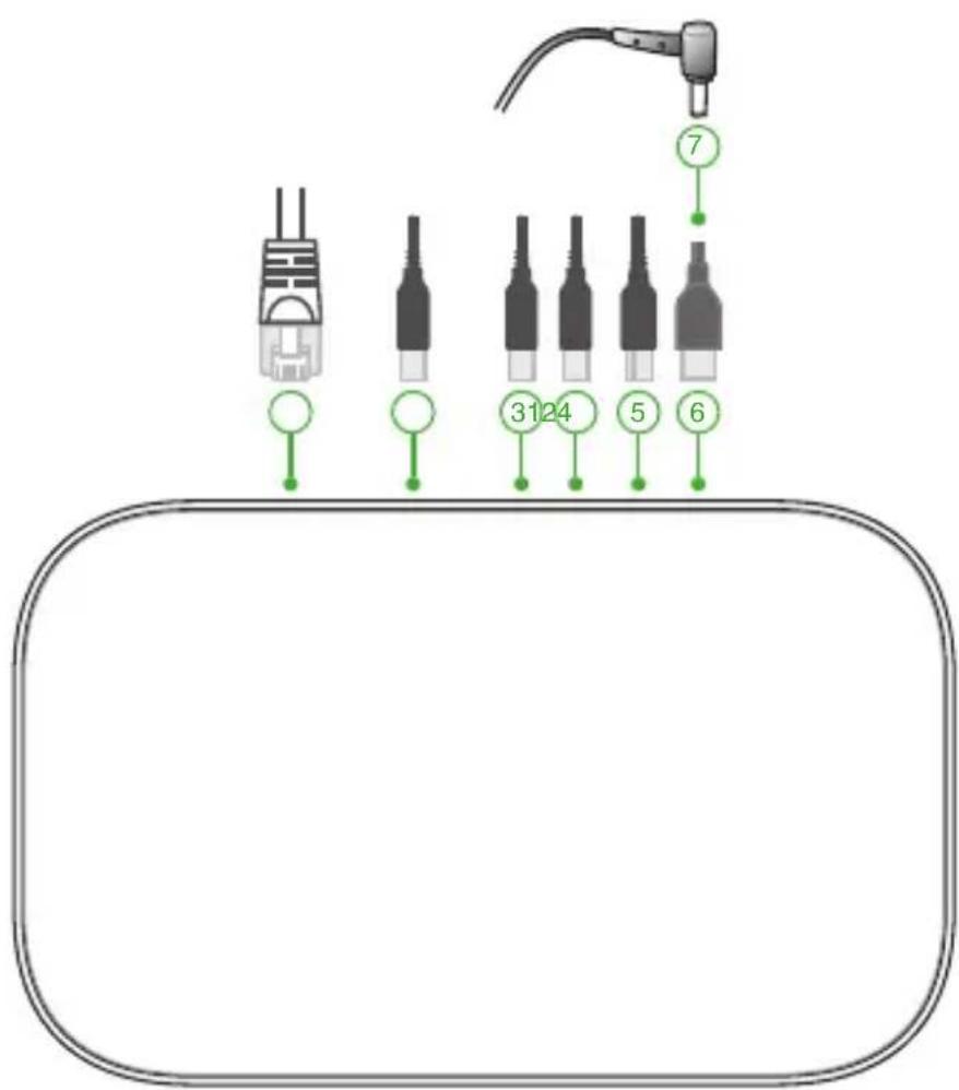
(FRONT WALL)(FRONT WALL) DISPLAY 120° MEET CAMERAConnect your cables
Using the included cables and sensor, connect your Meet Compute System to the other system components:
NOTE: The connections shown in the illustrations are recommended, you may adjust the connections accordingly to suit your needs.
text_image
3124 5 6 71
LAN port connects to a router.
NOTE: Although you can use your Meet Compute System device over a wireless network connection, we recommend using a wired network connection for optimal sound and video quality.
2
USB 3.2 Gen 1 port connects to a USB device.
③ USB 3.2 Gen 1 port connects the camera.
4 USB 3.2 Gen 1 port connects to the touchscreen
5 HDMI™ connects a display with HDMI™ connector.
6 USB 3.2 Gen 1 Type-C®/DisplayPort combo port connects to a USB device or an external display with a DisplayPort™ via a USB Type-C® adapter.
7 Power jack connects to a power outlet.
IMPORTANT! Be sure to connect to a power outlet last, after you have made all the other connections.
You can find connection instructions for your specific model on the Meet hardware kit product site.
Enroll your device
Complete basic enrollment
This section explains the basic enrollment flow, which works for almost all users. To learn about other options shown during the enrollment process, see Advanced enrollment options.
NOTE: We recommend connecting a USB keyboard to make entering the enrollment information easier.
To complete basic enrollment:
- Turn on the display.
- Turn on the Meet Compute System.
- Verify or change your language, keyboard layout, and network.
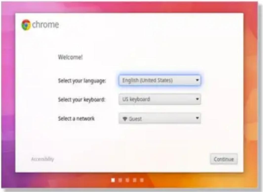
text_image
chrome Welcome! Select your language: English (United States) Select your keyboard: US keyboard Select a network Guest Accessibility ContinueNOTE: If your network doesn't appear in the Select a network list, select Join Network and enter the correct settings. Ask your network administrator for the settings if you don't know them.
-
Select Continue.
-
Accept the Google Terms of Service.
-
Sign in with your Google Workspace User Account email address and password.
-
The enrollment process takes place automatically. After the process is complete, click Done.
-
When the Google Meet screen appears, follow the onscreen instructions to test your camera and speakermic.
NOTE:
If you can't see video or hear audio during the test:
- Ensure that your camera and speakermic were connected to your Meet Compute System before you turned on your device.
- Ensure that your camera and speakermic are connected to your device properly.
-
Unplug the cables and plug them in again, then restart your device.
-
Click through the screens to view tips on using Meet Compute System.
At the end of device enrollment, the screen displays a URL for this device's page in the Google Admin Console. Using this URL, an admin user must add the room's online calendar to the device to enable scheduled meetings.
Advanced enrollment options
Users can go through the simple enrollment flow described in Complete basic enrollment to enroll their device. Additional options are available for users who want to customize the setup experience or learn more. These options appear on the second enrollment screen, except for accessibility, which appears on both the first and second screens:
Accessibility: Accessibility options include larger font and cursor size, voice prompts, and more. The options you select here apply to the setup process and Out-of-box experience (OOBE) process. To select the Accessibility link, press the Continue or Accept and continue button.
NOTE: High contrast mode only takes effect during enrollment and not in the OOBE process.
Help make Chrome OS better: Allows your device to send usage and crash info to Google helping us improve the Chrome OS experience for all users. To learn more about this option, click the Learn more link onscreen.
System security setting: Read more about the Meet Compute System security settings.
Google Chrome OS Terms: Scroll up and down to review the terms.
Manage devices and rooms
You can view, modify and update your Meet Compute System and rooms through the Google Admin console. For more details on managing your devices and rooms, please visit the Manage Google Meeting Room Hardware website.
Troubleshooting
Fix a problem
Manage devices and rooms
I do not know how to identify the Meet Compute System device I want on the device list screen.
If you are not sure which device to click, you can identify the correct one by its serial number. You can find your device's serial number on the card that was included in the box and on the bottom of the device itself.
Help and support
Visit Manage Google Meeting Room Hardware for more detailed set-up and provisioning instructions, customizable table mats, or to print guides for your users.
Appendix
Safety information
Your Meet Compute System is designed and tested to meet the latest standards of safety for information technology equipment. However, to ensure your safety, it is important that you read the following safety instructions.


- Do not ingest battery, Chemical Burn Hazard.
- This product contains a coin / button cell battery. If the coin /button cell battery is swallowed, it can cause severe internal burns in just 2 hours and can lead to death.
- Keep new and used batteries away from children.
- If the battery compartment does not close securely, stop using the product and keep it away from children.
- If you think batteries might have been swallowed or placed inside any part of the body, seek immediate medical attention.
Setting up your system
- Read and follow all instructions in the documentation before you operate your system.
- Do not use this product near water or a heated source.
- Set up the system on a stable surface.
- Openings on the chassis are for ventilation. Do not block or cover these openings. Make sure you leave plenty of space around the system for ventilation. Never insert objects of any kind into the ventilation openings.
- Use this product in environments with ambient temperatures between 0^ and 35^ .
- If you use an extension cord, make sure that the total ampere rating of the devices plugged into the extension cord does not exceed its ampere rating.
- This product should be connected by means of a power cord to a socket-outlet with earthing connection.
- This equipment should be installed and operated with a minimum distance of 20cm between the radiator and your body.
Care during use
- Do not walk on the power cord or allow anything to rest on it.
- Do not spill water or any other liquids on your system.
- When the system is turned off, a small amount of electrical current still flows. Always unplug the power cord from the power outlets before cleaning the system.
- If you encounter the following technical problems with the product, unplug the power cord and contact a qualified service technician or your retailer.
- The power cord or plug is damaged.
– Liquid has been spilled into the system.
- The system does not function properly even if you follow the operating instructions.
- The system was dropped or the cabinet is damaged.
- The system performance changes.
- Avoid contact with hot components inside the Meet Compute System.
During operation, some components become hot enough to burn the skin. Before you open the computer cover, turn off the computer, disconnect the power, and wait approximately 30 minutes for the components to cool.
- Disposal of a battery into fire or a hot oven, or mechanically crushing or cutting of a battery, that can result in an explosion;
• Leaving a battery in an extremely high temperature surrounding environment that can result in an explosion or the leakage of flammable liquid or gas;
- A battery subjected to extremely low air pressure that may result in an explosion or the leakage of flammable liquid or gas.
Lithium-Ion Battery Warning
CAUTION: Danger of explosion if battery is incorrectly replaced. Replace only with the same or equivalent type recommended by the manufacturer. Dispose of used batteries according to the manufacturer's instructions.
NO DISASSEMBLY
The warranty does not apply to the products that have been disassembled by users.
Regulatory notices
COATING NOTICE
IMPORTANT! To provide electrical insulation and maintain electrical safety, a coating is applied to insulate the device except on the areas where the I/O ports are located.
RF exposure warning
This equipment must be installed and operated in accordance with provided instructions and the antenna(s) used for this transmitter must be installed to provide a separation distance of at least 20 cm from all persons and must not be co-located or operating in conjunction with any other antenna or transmitter. End-users and installers must be provide with antenna installation instructions and transmitter operating conditions for satisfying RF exposure compliance.
Federal Communications Commission Statement
This device complies with Part 15 of the FCC Rules. Operation is subject to the following two conditions:
• This device may not cause harmful interference, and
- This device must accept any interference received including interference that may cause undesired operation.
This equipment has been tested and found to comply with the limits for a Class B digital device, pursuant to Part 15 of the FCC Rules. These limits are designed to provide reasonable protection against harmful interference in a residential installation. This equipment generates, uses and can radiate radio frequency energy and, if not installed and used in accordance with manufacturer's instructions, may cause harmful interference to radio communications. However, there is no guarantee that interference will not occur in a particular installation.
If this equipment does cause harmful interference to radio or television reception, which can be determined by turning the equipment off and on, the user is encouraged to try to correct the interference by one or more of the following measures:
- Reorient or relocate the receiving antenna.
- Increase the separation between the equipment and receiver.
- Connect the equipment to an outlet on a circuit different from that to which the receiver is connected.
- Consult the dealer or an experienced radio/TV technician for help
CAUTION! Changes or modification not expressly approved by the grantee of this device could void the user's authority to operate the equipment.
NOTE: This PC does not support PoE switches.
Responsible Party: Asus Computer International
Address: 48720 Kato Rd, Fremont, CA 94538
Phone/Fax No: (510)739-3777/(510)608-4555
HDMI Trademark Notice
The terms HDMI, HDMI High-Definition Multimedia Interface, and the HDMI Logo are trademarks or registered trademarks of HDMI Licensing Administrator, Inc.
ISED Radiation Exposure Statement for Canada
This equipment complies with ISED radiation exposure limits set forth for an uncontrolled environment. To maintain compliance with ISED RF exposure compliance requirements, please avoid direct contact to the transmitting antenna during transmitting. End users must follow the specific operating instructions for satisfying RF exposure compliance.
Operation is subject to the following two conditions:
• This device may not cause interference and
- This device must accept any interference, including interference that may cause undesired operation of the device.
Compliance Statement of Innovation, Science and Economic Development Canada (ISED)
This device complies with Innovation, Science and Economic Development Canada licence exempt RSS standard(s). Operation is subject to the following two conditions: (1) this device may not cause interference, and (2) this device must accept any interference, including interference that may cause undesired operation of the device.
CAN ICES-003(A)/NMB-003(A)
Wireless Operation Channel for Different Domains
N. America 2.412-2.462 GHz Ch01 through CH11
Japan 2.412-2.484 GHz Ch01 through Ch14
Europe ETSI 2.412-2.472 GHz Ch01 through Ch13
Declaration of compliance for product environmental regulation
ASUS follows the green design concept to design and manufacture our products, and makes sure that each stage of the product life cycle of ASUS product is in line with global environmental regulations. In addition, ASUS disclose the relevant information based on regulation requirements.
Please refer to http://csr.asus.com/Compliance.htm for information disclosure based on regulation requirements ASUS is complied with:
EU REACH and Article 33
Complying with the REACH (Registration, Evaluation, Authorization, and Restriction of Chemicals) regulatory framework, we publish the chemical substances in our products at ASUS REACH website at http://csr.asus.com/english/REACH.htm
EU RoHS
This product complies with the EU RoHS Directive. For more details, see http://csr.asus.com/english/article.aspx?id=35
ASUS Recycling/Takeback Services
ASUS recycling and takeback programs come from our commitment to the highest standards for protecting our environment. We believe in providing solutions for you to be able to responsibly recycle our products, batteries, other components as well as the packaging materials. Please go to http://csr.asus.com/english/Takeback.htm for detailed recycling information in different regions.
Ecodesign Directive
European Union announced a framework for the setting of ecodesign requirements for energy-related products (2009/125/EC). Specific Implementing Measures are aimed at improving environmental performance of specific products or across multiple product types. ASUS provides product information on the CSR website. The further information could be found at https://csr.asus.com/english/article.aspx?id=1555.
DO NOT throw the device in municipal waste. This product has been designed to enable proper reuse of parts and recycling. This symbol of the crossed out wheeled bin indicates that the product (electrical, electronic equipment, and mercury-containing button cell battery) should not be placed in municipal waste. Check local technical support services for product recycling.
ENERGY STAR Qualified Product

text_image
energy ENERGY STARENERGY STAR is a joint program of the U.S.
Environmental Protection Agency and the U.S.
Department of Energy helping us all save money and protect the environment through energy efficient products and practices.
All ASUS products with the ENERGY STAR logo comply with the ENERGY STAR standard, and the power
management feature is enabled by default. The monitor is automatically set to sleep within 10 minutes of user inactivity; the computer is automatically set to sleep within 30 minutes of user inactivity. To wake your computer, click the mouse, press any key on the keyboard, or press the power button.
Please visit http://www.energystar.gov/powermanagement for detail information on power management and its benefits to the environment. In addition, please visit http://www.energystar.gov for detail information on the ENERGY STAR joint program.
NOTE: Energy Star is NOT supported on FreeDOS and Linux-based products.
EPEAT (Electronic Product Environmental Assessment Tool) registered products
The public disclosure of key environmental information for ASUS EPEAT registered products is available on CSR web site http://csr.asus.com/english/article.aspx?id=41. More information about EPEAT program and purchaser guidance can be found on the EPEAT website www.epeat.net.
EU: Radio Equipment Directive
(Directive 2014/53/EU)
Simplified EU Declaration of Conformity
ASUSTek Computer Inc. hereby declares that this device is in compliance with the essential requirements and other relevant provisions of Directive 2014/53/EU. Full text of EU declaration of conformity is available at https://www.asus.com/support/.
The WiFi operating in the band 5150-5350MHz shall be restricted to indoor use for countries listed in the table below:
CE Mark Warning
This is a Class A product, in a domestic environment, this product may cause radio interference, in which case the user may be required to take adequate measures.

| AT BE BG CZ DK EE FR | ||||||
| DE IS IE IT EL ES CY | ||||||
| LV | LI | LT | LU | HU | MT | NL |
| NO | PL PT RO SI SK TR | |||||
| FI SE CH | HR | UK(NI) | ||||
CE RED RF Output table (Directive 2014/53/EU)
AX201NGW (Model: GQE15A) output power table:
| Function Frequency Maximum Output Power (EIRP) | |
| WiFi | 2412-2472 MHz 20 dBm |
| 5150-5350 MHz 23 dBm | |
| 5470-5725 MHz 23 dBm | |
| 5725-5850 MHz 13.95 dBm | |
| Bluetooth 2402-2480 MHz 13.6 dBm | |
For the standard EN 300 440, if this device operates in 5725-5875 MHz, it will be considered as a receiver category 2.
| Manufacturer ASUSTek COMPUTER INC. | |
| Address, City 1F., No. 15, Lide | Rd., Beitou Dist., Taipei City 112, Taiwan |
| Authorized Representative in Europe | ASUS COMPUTER GmbH |
| Address Harkortstrasse 21-23, | 40880 Ratingen |
| Country Germany | |
| Authorized Representative in United Kingdom | ASUSTEK (UK) LIMITED |
| Address 1st Floor, Sackville House, | 143-149 Fenchurch Street,London, EC3M 6BL, England |
| Country United Kingdom | |
FCC COMPLIANCE INFORMATION
Per FCC Part 2 Section 2.1077

Responsible Party: Asus Computer International
Address: 48720 Kato Rd, Fremont, CA 94538.
Phone/Fax No: (510)739-3777/(510)608-4555
hereby declares that the product
Product Name : Meet Compute System
Model Number : GQE15A
compliance statement:
This device complies with part 15 of the FCC Rules. Operation is subject to the following two conditions: (1) This device may not cause harmful interference, and (2) this device must accept any interference received, including interference that may cause undesired operation.
Ver. 180620
ASUS-Google Meet hardware kit GQE15A
natural_image
Line drawing of a rectangular electronic device with ventilation slots and a small port (no text or symbols)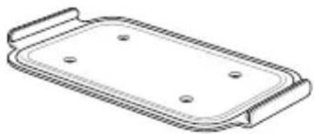
natural_image
Line drawing of a rectangular tray with four circular holes, no text or symbols presentMeet Compute System Support de fixation murale
natural_image
Line drawing of a cable with two connectors (no text or symbols)natural_image
Line drawing of a rectangular electronic device with a coiled cable and terminal connector (no text or symbols)natural_image
Simple line drawing of a flat rectangular object with a slot (no text or symbols)
text_image
IN SEARCH OF INCREBBIBLE ——Documentation technique
Périphériques :
natural_image
Line drawing of a tablet device with front and back views (no text or symbols)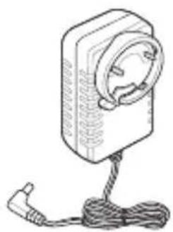
natural_image
Line drawing of a portable electronic device with a circular button and cable (no text or symbols)natural_image
Coiled network cable with two connectors (no text or symbols visible)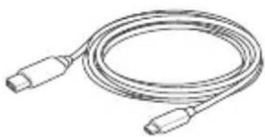
natural_image
Line drawing of a coiled cable with two connectors (no text or symbols)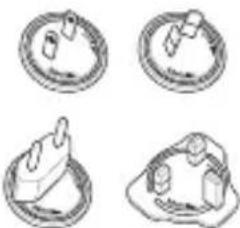
natural_image
Four circular diagrams showing different mechanical or architectural components, no text or symbols present.natural_image
Technical line drawing of a mechanical component with a cylindrical top and flange (no text or symbols)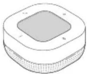
natural_image
Simple line drawing of a square-shaped object with a textured base and central square (no text or symbols)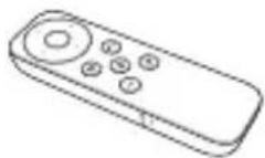
natural_image
Line drawing of a flexible cable with two connectors (no text or symbols)
natural_image
Pure diagram of a rectangular container with internal rows, no text or symbols presentnatural_image
Front view of a server rack with a button and indicator light (no text or symbols)flowchart
graph TD
    A["1"] --> B["Process Box"]
1 Encoche du socle de fixation
natural_image
Line drawing of a portable electronic device with ports and cables (no text or symbols)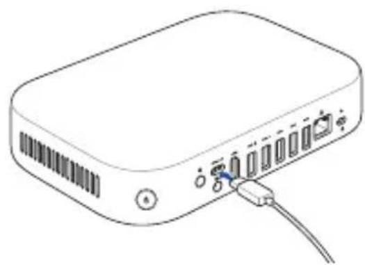
natural_image
Line drawing of a rectangular electronic device with ports and an attached cable (no text or symbols)text_image
Diagram showing connected devices with labeled components A, B, and C, illustrating cable connections and connectivity.Connector la caméra
natural_image
Line drawing of a portable electronic device with cable and connector (no text or symbols)text_image
Diagram showing a device connected to a wall-mounted power outlet, with labeled components A and B indicating parts of the device.natural_image
Line drawing of a rectangular electronic device with ports and connectors, no text or symbols presenttext_image
Diagram showing cable connections to a device with labeled parts A, B, and C, including a close-up of electrical plug details.IMPORTANT!
natural_image
Illustration of a desktop computer setup with a laptop, keyboard, mouse, and power button (no text or symbols)3
Configuration de votre kit ASUS - Google Meet
text_image
Diagram showing a device with labeled components and directional arrows, alongside its 3D view of the internal panel.natural_image
Diagram showing a device connected to a rectangular panel with a blue arrow indicating direction (no text or symbols present)natural_image
Line drawing of a rectangular electronic device with a flat top and side slot (no text or symbols)natural_image
Diagram showing a device connected to a device via a cable, with no visible text or symbols.natural_image
Line drawing of a wireless router device with ports and ventilation slots (no text or symbols)Placer la caméra
text_image
chrome Welcome! Select your language: English (United States) Select your keyboard: US keyboard Select a network Guest Accessibility ContinuePer FCC Part 2 Section 2.1077

Responsible Party: Asus Computer International
Address: 48720 Kato Rd, Fremont, CA 94538.
Phone/Fax No: (510)739-3777/(510)608-4555
hereby declares that the product
Product Name : Meet Compute System
Model Number : GQE15A
compliance statement:
This device complies with part 15 of the FCC Rules. Operation is subject to the following two conditions: (1) This device may not cause harmful interference, and (2) this device must accept any interference received, including interference that may cause undesired operation.
Ver. 180620