UCC15NJII - Ice machine GE - Free user manual and instructions
Find the device manual for free UCC15NJII GE in PDF.

User questions about UCC15NJII GE
0 question about this device. Answer the ones you know or ask your own.
Ask a new question about this device
Download the instructions for your Ice machine in PDF format for free! Find your manual UCC15NJII - GE and take your electronic device back in hand. On this page are published all the documents necessary for the use of your device. UCC15NJII by GE.
USER MANUAL UCC15NJII GE
Safety Instructions....2,3
Remove Packaging 4
Operating Instructions
Controls and Features 4,5
Starting the Ice Machine 5
Care and Cleaning 6 - 7
Installation Instructions
Grounding the Ice Machine ..... 8
Before You Begin 8
Location and Preparation 8,9
Installing the Ice Machine ..... 10 - 16
Advanced Planning 10
Accessories 10
Installation Notes 10
Dimensions 11
Door Swing 12
Installing the Door Panel.....13, 14
Plumbing 15
Installation....15
Troubleshooting Tips....16
Noise 16
Consumer Support
Warranty 17
Consumer Support 18
Write the model and serial numbers here:
Model # ____
Serial #
Find these numbers on a label on the top inner case liner of the unit toward the front.
Owner's Manual and Installation Instructions
UCC15
SAFETY
GE Appliances website
For more information on your appliance operation, visit www.GEAppliances.com or call 800.GECARES (800.432.2737). In Canada visit GEAppliances.ca or call 800.561.3344.
ICE MACHINE SAFETY INFORMATION
This is the safety alert symbol. This symbol alerts you to potential hazards that can kill or hurt you and others. All safety messages will follow the safety alert symbol and the word "DANGER", "WARNING", or "CAUTION". These words are defined as:

DANGER

WARNING

CAUTION
Indicates a hazardous situation which, if not avoided, will result in death or serious injury.
Indicates a hazardous situation which, if not avoided, could result in death or serious injury.
Indicates a hazardous situation which, if not avoided, could result in minor or moderate injury.
IMPORTANT SAFETY INSTRUCTIONS
WARNING
To reduce the risk of fire, explosion, electric shock, or injury when using your ice machine follow these basic safety precautions:
This ice machine must be properly installed and located in accordance with the Installation Instructions before it is used.
■ Unplug the appliance before making repairs, replacing a light bulb, or cleaning.
Note: Power to the appliance cannot be disconnected by any setting on the control panel.
Note: Repairs must be performed by a qualified service professional.
- Replace all parts and panels before operating.
- Do not store or use gasoline or other flammable vapors and liquids in the vicinity of this or any other appliance.
Because of potential safety hazards under certain conditions, we strongly recommend against the use of an extension cord. However, if you must use an extension cord, it is absolutely necessary that it be a UL-listed (in
the United States) or a CSA certified (in Canada), 3-wire grounding type appliance extension cord having a grounding type plug and outlet and that the electrical rating of the cord be 15 amperes (minimum) and 120 volts.
To prevent suffocation and entrapment hazards to children, remove the door from any appliance before disposing of it or discontinuing its use.
- Do not allow children to climb, stand or hang on the door handle of the appliance. They could seriously injure themselves.
Ice machine scale remover contains acids. Acids can cause burns. If concentrated cleaner comes in contact with skin, flush with water. If swallowed, do NOT induce vomiting. Give large amounts of water or milk. Call Physician immediately. Keep out of the reach of children.

CAUTION
To reduce the risk of injury when using your appliance, follow these basic safety precautions.
- Keep fingers out of the “pinch point” areas; clearances between the doors and between the doors and cabinet are necessarily small. Be careful closing doors when children are in the area.
Avoid contact with the moving parts of the ejector mechanism, or with the heating element that releases the cubes. Do not place fingers or hands on the automatic ice making mechanism while the ice machine is plugged in.
INSTALLATION

WARNING

Explosion Hazard.
Keep flammable materials and vapors, such as gasoline, away from appliance. Failure to do so can result in fire, explosion, or death.
SAFETY (CONT.)
OUTDOOR USE NOTICE:
KEEP FROM FREEZING: Severe damage will occur to the unit if left in or operated in temperatures beyond the limits listed in this manual. That damage is NOT covered by warranty.
KEEP DRY: Do not locate in low lying areas where puddles will accumulate
PROVIDE SHADE: Heat gain from the sun will reduce the unit's ability to make and store ice, and ultraviolet radiation from the sun can potentially damage the unit's plastic components.
WATER SUPPLY: Avoid a long run of hose or tubing exposed to the sun. Plastic water supply tubing should be rated for
potable water and include UV protection. Copper tubing is recommended.
BACK FLOW PREVENTION: The unit includes back flow prevention, no additional check valve is required.
DRAINAGE: DO NOT drain into swimming pool or onto grounds.
OPERATION: It is normal for the ice level in the storage bin to be low when unit is used in temperatures below 65^ F.
CONNECTING ELECTRICITY
WARNING
Electrical Shock Hazard.
Plug into a grounded 3-prong outlet
Do not remove the ground prong
Do not use an adapter
Failure to follow these instructions can result in death, fire, or electrical shock.
Do not, under any circumstances, cut or remove the third (ground) prong from the power cord.
For personal safety, this appliance must be properly grounded.
The power cord of this appliance is equipped with a 3-prong (grounding) plug which mates with a standard 3-prong (grounding) wall outlet to minimize the possibility of electric shock hazard from this appliance.
Have the wall outlet and circuit checked by a qualified electrician to make sure the outlet is properly grounded.
Where a standard 2-prong wall outlet is encountered, it is your personal responsibility and obligation to have it replaced with a properly grounded 3-prong wall outlet.
The ice maker should always be plugged into its own 115 volt, 60 Hz, 15 amp circuit. This provides the best
performance and also prevents overloading house wiring circuits which could cause a fire hazard from overheated wires.
Never unplug your ice maker by pulling on the power cord. Always grip plug firmly and pull straight out from the outlet.
Repair or replace immediately all power cords that have become frayed or otherwise damaged. Do not use a cord that shows cracks or abrasion damage along its length or at either end.
When moving the ice maker, be careful not to roll over or damage the power cord.
PROPER DISPOSAL OF YOUR OLD APPLIANCE
WARNING
Suffocation and child entrapment hazard.
Remove the door from the appliance prior to disposal. Failure to do so can result in child entrapment which can lead to death or brain damage.
IMPORTANT:
Child entrapment and suffocation are not problems of the past. Junked or abandoned appliances are still dangerous even if they will sit for "just a few days." If you are getting rid of your old appliance, please follow the instructions below to help prevent accidents.
Before You Throw Away Your Old Appliance:
Take off the doors.
Leave the internal components in place so that children may not easily climb inside.
Refrigerants
All refrigeration products contain refrigerants, which under federal law must be removed prior to product disposal. If you are getting rid of an old refrigeration product, check with the company handling the disposal about what to do.
READ AND FOLLOW THIS SAFETY INFORMATION CAREFULLY.
SAVE THESE INSTRUCTIONS
Remove packaging
IMPORTANT: Do not remove any permanent instruction labels inside your ice machine or the Tech Sheet that is fastened behind the lower access panel.
- Remove tape and any labels from your ice maker before using (except the model and serial number label).
To remove any remaining tape or glue, rub the area briskly with your thumb. Tape or glue residue can also be easily removed by rubbing a small amount of liquid dish soap over the adhesive with your fingers. Wipe with warm water and dry.
- Do not use sharp instruments, rubbing alcohol, flammable fluids or abrasive cleaners to remove tape or glue. These products can damage the surface of your ice maker. For more information, see Important Safety Instructions.
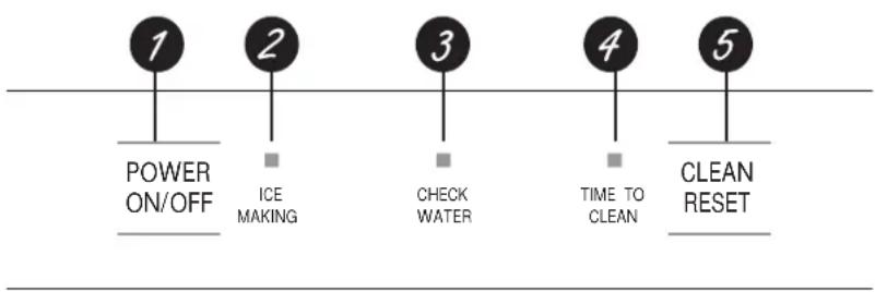
About the controls and features.
flowchart
graph LR
    A["1 POWER ON/OFF"] --> B["2 ICE MAKING"]
    B --> C["3 CHECK WATER"]
    C --> D["4 TIME TO CLEAN"]
    D --> E["5 CLEAN RESET"]
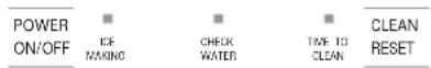
1 POWER ON/OFF - Press to turn the ice machine on or off.
2 ICE MAKING - Glows white when the unit is ON.
3 CHECK WATER - Glows red when there is not water supplied to the machine.
4 TIME TO CLEAN - Glows yellow when it's time to clean the machine. The light will switch ON after 6 months of use. It will remain on until the ice making system is cleaned using the process in the Care and cleaning section
5 CLEAN RESET - Pressed with Power button for 5 seconds to start the cleaning process (see Care and Cleaning).
text_image
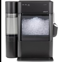
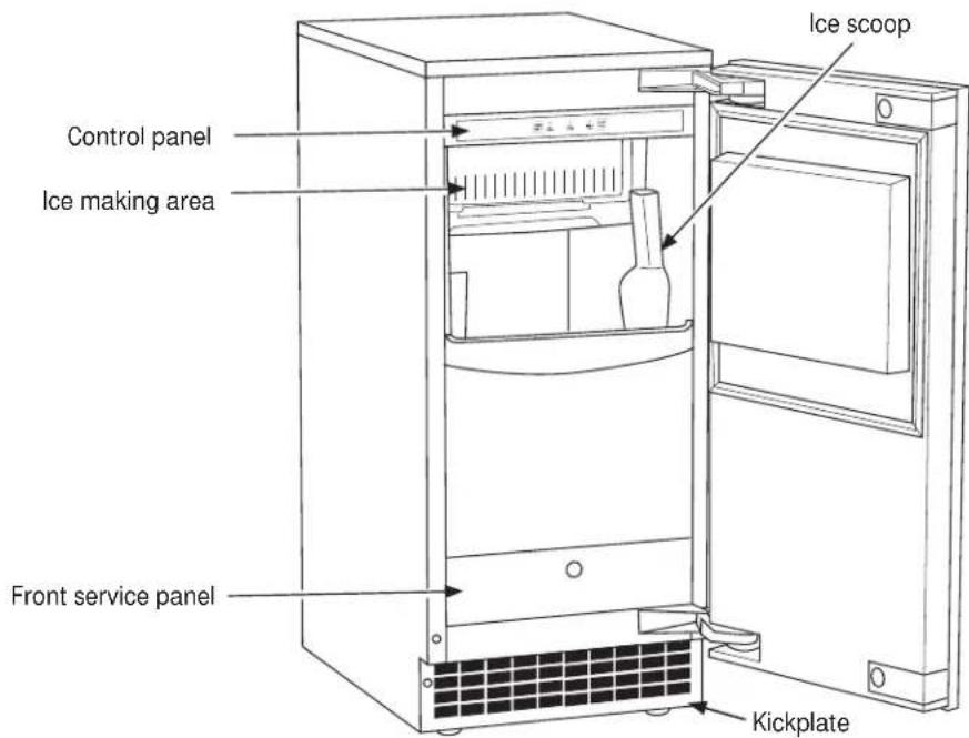
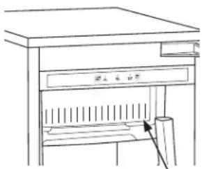
Control panel Ice making area Front service panel Ice scoop KickplateStarting the ice machine.
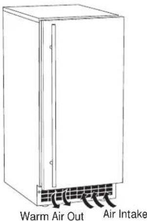
This machine takes in room temperature air at the lower right front and forces warm air out the lower left front. Restricting the airflow or operating the machine in a hot or cold environment will adversely affect the ability of the ice machine to make ice.
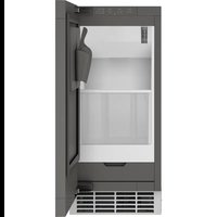
When the door is opened, the control panel, ice making area and ice storage bin are visible. The scoop is located in a holder along the right side wall.
This is a gravity drain model that must have a building drain connection below the level of the drain tube at the back of the cabinet. A pump can be installed, which can force drain water up a maximum of 10 feet, allowing it to be located where a gravity drain isn't available. See Accessories on page 10 for more information on the drain pump.
Initial Start Up
- Turn on the water supply.
- Switch on the electrical power.
- Push and release the ON/OFF switch to start the machine. The ICE MAKING light next to the ON/OFF switch will glow white.
- Water will begin to flow into the unit. When the reservoir is full, water will start to drain from the machine. After a few minutes the compressor, water pump and fan motor will begin to operate as the first ice making cycle begins.
text_image
Warm Air Out Air IntakeNo adjustments are needed.
In approximately 30 minutes, ice will fall into the ice storage bin. The machine makes 24 gourmet cubes at a time. It is normal for the first batches of ice to melt as the bin cools. It will take 8-10 hours of continuous run time to fill the ice bin. When the ice bin is full, the ice machine will shut off. It will automatically restart when the ice level falls, either from use or normal meltage.
Discard the first bin full of ice.
Care and cleaning.
Cleaning the Outside
The stainless steel door and door handle can be cleaned with a commercially available stainless steel cleaner. Cleaners with oxalic acid such as Bar Keepers Friend Soft Cleanser™ will remove surface rust, tarnish and small blemishes.
Use only a liquid cleanser free of grit and rub in the direction of the brush lines with a damp soft sponge. Do not use appliance wax or polish on the stainless steel.
Cleaning the Ice Storage Bin
The ice storage bin should be sanitized occasionally. It is usually convenient to sanitize the bin after the ice making system has been cleaned and the bin is empty.
A sanitizing solution can be made of 1 oz of household bleach and 2 gallons of hot (95°F - 115°F) water. Use a clean cloth and wipe the interior of the ice storage bin with the sanitizing solution. Pour some of the solution down the drain.
Allow to air dry.
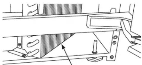
Cleaning the Condenser
The condenser has fins and tubes that can become clogged with dirt and lint.
NOTE: Outdoor operation can lead to rapid buildup of debris, such as leaves and other vegetation. The condenser will need to be frequently checked for debris. Clean it whenever the fins are obstructed.
To clean:
- Remove the kickplate and front service panel.
- Locate the condenser surface.
natural_image
Technical line drawing of a mechanical assembly with no visible text or symbolsCondenser surface
- Vacuum the surface to remove all dust, dirt, and lint.

NOTICE
Do not dent the fins.
- Return the kickplate and front service panel to their original positions. Fasten them to the cabinet using the original screws.
Winterizing
- Clean the ice making system per the instructions above.
- Open the door. Push the ON/OFF button to turn the ice machine off.
- Turn off the water supply.
- Drain the water reservoir by removing the rubber stopper under the reservoir. It is located near the back wall of the ice storage bin.
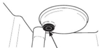
natural_image
Simple line drawing of a mechanical component with a circular top and triangular base (no text or symbols)Rubber stopper
- Disconnect the incoming water line at the inlet water valve.
- Open the door. Push the ON/OFF button to turn the ice machine on.
- Blow air through the inlet water valve. A tire pump can be used.
- Models with a drain pump installed should have about 1/2 gallon of RV antifreeze (propylene glycol) poured into the ice storage bin drain.
NOTE: Automotive antifreeze must NOT be used.
- Turn off and unplug the machine.
Removing Scale from the Ice Making System
The TIME TO CLEAN light will come on after 6 months of use. It will remain on until the ice making system has been cleaned. You should use rubber gloves when using the scale remover. To order scale remover, go to www.GEAppliances.com or call 800.GECARES (800.432.2737). In Canada visit www.GEAppliances.ca or call 800.561.3344. Order part number WX08X42873.

WARNING

Ice machine scale remover contains acids. Acids can cause burns. If concentrated cleaner comes in contact with skin, flush with water. If swallowed, do NOT induce vomiting. Give large amounts of water or milk. Call Physician immediately. Keep out of the reach of children.
- Scoop out all of the ice in the ice bin. Discard the ice or save it in an ice chest or cooler.
- Press and hold the ON/OFF button for 3 seconds until the white light goes out.
- Press and hold both the CLEAN-RESET and ON/OFF buttons for 5 seconds. The TIME TO CLEAN light will blink on and off.
- Pour 8 oz of ice machine scale remover into the ice machine reservoir.
natural_image
Line drawing of a cabinet with an open drawer and a paper stack, no text or symbols presentPour scale remover
- Operate the machine for about 1/2 hour.
- Push and release the ON/OFF switch. The machine will begin to flush out the cleaning solution.
- Operate the machine for another 1/2 hour.
- Push and release the ON/OFF switch. The machine will stop the cleaning process.
- Pour a gallon of hot water into the bin to flush out the drain.
- Clean the bin liner of mineral scale by mixing some ice machine scale remover and hot water, and using that solution to scrub the scale off of the liner.
- Rinse the liner with hot water.
- Sanitize the bin interior.
- Replace the ice removed in step 1 if applicable.
- Push and release the ON/OFF button to restart ice making.
- The ice scoop should be washed regularly and is dishwasher safe.
Normal gourmet cubes are tapered cylinders. If the gourmet cubes are ragged and miss-shaped, mineral scale must be removed from the ice making system.
Note: The bin is insulated and not refrigerated so the ice form will change in the storage bin as it is normal for the ice to melt
Installation Instructions
Ice Machine
Questions? Call 800.GE.CARES (800.432.2737) or visit our Website at: GEAppliances.com
In Canada, call 1.800.561.3344 or visit our Website at: www.GEAppliances.ca
GROUNDING THE ICE MACHINE
WARNING

Electrical Shock Hazard.
Failure to follow these instructions can result in death, fire, or electrical shock.
The power cord of this appliance is equipped with a 3-prong (grounding) plug which mates with a standard 3-prong (grounding) wall outlet to minimize the possibility of electric shock hazard from this appliance.
Have the wall outlet and circuit checked by a qualified electrician to make sure the outlet is properly grounded.
Where a standard 2-prong wall outlet is encountered, it is your personal responsibility and obligation to have it replaced with a properly grounded 3-prong wall outlet. DO NOT, UNDER ANY CIRCUMSTANCES, CUT OR REMOVE THE THIRD (GROUND) PRONG FROM THE POWER CORD.
DO NOT USE AN ADAPTER PLUG TO CONNECT THE ICE MACHINE TO A 2-PRONG OUTLET.
DO NOT USE AN EXTENSION CORD WITH THIS APPLIANCE.
BEFORE YOU BEGIN
Read these instructions completely and carefully.
- IMPORTANT — Observe all governing codes and ordinances. Save these instructions for local inspector's use.
- Note to Installer – Be sure to leave these instructions with the Consumer.
- Note to Consumer – Keep these instructions for future reference.
- Skill level – Installation of this appliance requires basic mechanical skills.
- Completion time – Installation can vary
Water Line Installation 30 minutes
• Proper installation is the responsibility of the installer. - Product failure due to improper installation is not covered under the Warranty.
ICE MACHINE LOCATION AND PREPARATION
This ice machine is designed to be used indoors, in a controlled environment or outdoors within certain limits. It is made up of two major systems: the ice making system and the ice storage system. The ice making system is a continuous flow that makes ice when the ice level becomes low and stops when it is full.
IMPORTANT: Never keep anything in the ice storage bin that is not ice. Objects like wine or beer bottles are not only unsanitary, but the labels can slip off and plug up the drain.
IMPORTANT: Never allow the machine to operate without regular cleaning. The machine will last longer if it is kept clean. Regular cleaning should happen at least once per year, and preferably twice. Some water conditions will dictate even more frequent cleaning of the ice making section, and some carpets or pets will dictate more frequent cleaning of the condenser
Specifications
The ice machine will operate adequately within the limits, but functions best in temperatures between 70^ F and 80^ F.
• Minimum air temperature: 50°F (10°C)
• Maximum air temperature: 100°F (38°C)
• Minimum water temperature: 40^ F ( 4.5^ C)
• Maximum water temperature: 100°F. (38°C)
• Minimum water pressure: 20 psi (1.4 bar)
• Maximum water pressure: 80 psi (5.5 bar)
Electrical voltage limits:
• Minimum - 104 volts
• Maximum - 126 volts
ICE MACHINE LOCATION AND PREPARATION (Cont)
Water Quality
All water, including potable water supplied by municipalities, contains some impurities or minerals. Water absorbs impurities from the air as rain and/or as it flows through the ground. Some of the impurities are solid particles. These are known as suspended solids, and a fine particle filter will remove them. Other impurities are chemically bonded to the water molecules and cannot be filtered out. These are called dissolved solids.
Ice made by this machine will have a lower mineral content than the water it was made from. This is due to the method of making ice. Purer water will freeze first in the ice making molds. The reason for this is that anything dissolved in water lowers the water's freezing temperature. This concentrates most of the impurities of the ice machine water reservoir where they may form hard deposits known as scale. The machine dilutes the concentration of minerals by over-filling the reservoir during the harvest cycle (with the excess water flowing down the drain). Water use varies with air and water temperatures. Between 2 and 4 pints of water flow into the unit each cycle. Between 1 and 3.5 pints of that rinses the reservoir and goes down the drain.
Some impurities will inevitably remain, and will stick to the parts in the machine. This will cause malformed ice cubes. Eventually, built up mineral scale can shorten machine life.
To keep the machine operating properly, these impurities or minerals will have to be regularly dissolved by an acid cleaner. Directions for this may be found in the Care and Cleaning section.
Filters and Treatment
In general, it is always a good idea to filter the water. A proper water filter can remove taste and odors as well as particles. We recommend using a GE Water Filter on your water inlet line such as GE Model Number GXRLQ. Please go to www.geappliances.com to review the installation instructions and determine which filter will suit your application. In Canada visit www.GEAppliances.ca. Some other methods of water treatment for dissolved solids include reverse osmosis, and polyphosphate feeders.
RO Water
This machine can be supplied with Reverse Osmosis water, but the water conductivity must be no less than 10 microSiemens/cm. A reverse osmosis system should include post treatment to satisfy the R.O. water's potential aggressiveness. Deionized water is not recommended.
Because water softeners exchange one mineral for another, softened water may not improve water conditions when used with ice machines. Where water is very hard, softened water could result in white, mushy cubes that stick together.
If in doubt about the water, contact a local point of use water specialist for recommendations on water treatment.
Installation Overview
The ice machine must:
- be connected to cold, potable water
- be connected to a drain
- be connected to the proper power supply
- be able to circulate air through the vents at the front.
NOTE: Do not build in so that the door is recessed.
INSTALLING THE ICE MACHINE (Cont.)
ADVANCE PLANNING
CAUTION
Due to excessive weight, TWO
PEOPLE ARE REQUIRED TO MOVE AND INSTALL THIS Ice maker. Failure to do so can result in back or other injury.
CUTOUT & PRODUCT DIMENSIONS
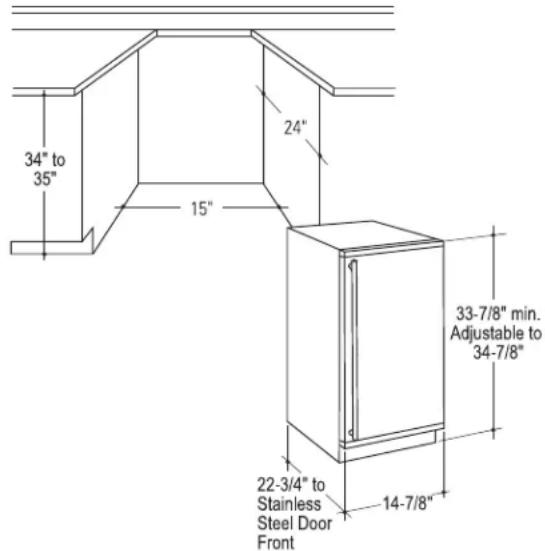
text_image
34" to 35" 24" 15" 33-7/8" min. Adjustable to 34-7/8" 22-3/4" to Stainless Steel Door Front 14-7/8"Installation Notes
Built-In Installation: If a finished floor is to be installed in the area after the ice machine has been built in, shims the expected thickness of the floor should be installed under the unit to keep the machine level with the planned floor level.
NOTE: The water connection is at the back and adds a few inches to the cabinet depth.
Installation on a slab: You will need to install a drain pump to the appliance and pump the water to the point of drainage. See Accessories. Pump models will pump 1 story (10 feet) hight.
Installation over a crawl space or basement: Either a gravity drain or a pump may be used. For pump, see Accessories. If there is not enough room behind the machine for a drain/waste receptacle, the drain will have to be below the floor.
NOTE: When installed in a corner, the door swing may be limited due to handle contact with the wall or cabinet face.
A water supply is required. Water supplies vary in the degree of mineral content. High mineral content water will require more frequent maintenance. Water filtration may improve the taste of the ice as well as cut down on some of the mineral build up.
ACCESSORIES
Finished stainless steel door panels with handles are available from GE Appliances for attachment to the ice machine. The panel kits are:
- ZIP80SS - Stainless steel door with Euro Style Handles
- PIP70SS - Stainless steel door with Profile Style Handles
• CIP75SS - Stainless steel door with Café Style Handles
To order, go to www.GEApplianceParts.com or call 877-959-8688. In Canada visit www.GEAppliances.ca or call 800.561.3344.
Kickplate Extension: In some situations the leg levelers will be extended enough to become visible. A kit to extend the kickplate over the legs (WR02X25798) is available. To order, go to www.GEApplianceParts.com or call 877-959-8688. In Canada visit www.GEAppliances.ca or call 800.561.3344..
Cabinet Stability: In some free standing installations it may be prudent to add an anti-tip bracket that secures the back of the cabinet to a wall. That kit number is WR01X25709.
To order, go to www.GEApplianceParts.com or call 877-959-8688. In Canada visit www.GEAppliances.ca or call 800.561.3344.
Drain Conversion: A gravity drain model can be converted to a drain pump model by installing a drain pump kit. The drain pump kit consists of a drain pump, wiring harness and associated tubing. The part number is UPK3. To order, go to www.GEApplianceParts.com or call 877-959-8688. In Canada visit www.GEAppliances.ca or call 800.561.3344.
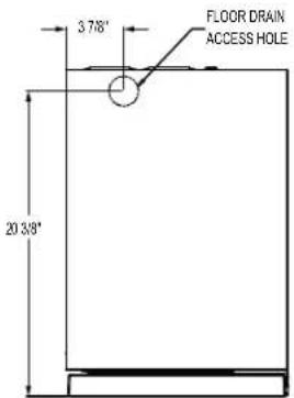
DIMENSIONS
text_image
3 7/8" FLOOR DRAIN ACCESS HOLE 20 3/8"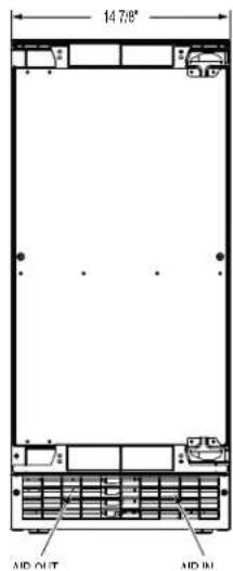
text_image
14.78" AID OUT AID IN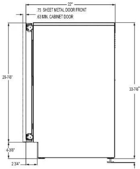
text_image
.75 SHEET METAL DOOR FRONT .63 MIN. CABINET DOOR 22" 29-7/8" 4-3/8" 2 3/4" 33-7/8"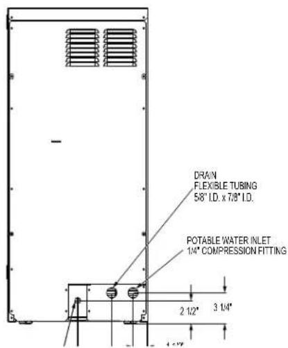
text_image
DRAN FLEXIBLE TUBING 5/8" I.D. x 7/8" I.D. POTABLE WATER INLET 1/4" COMPRESSION FITTING 2 1/2" 3 1/4"INSTALLING THE ICE MACHINE (Cont.)
DOOR SWING
Moving the hinges allows the door to open from either the left or the right side. Change the swing BEFORE attaching the door panel.
To change:
- Open the door. Remove 4 stainless steel screws opposite the hinge side on the front of the cabinet.
- Remove innermost screw holding each hinge to the cabinet. Loosen the other screw.
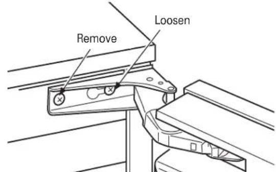
text_image
Remove Loosen- Slide the door to the side so the keyhole on the hinge clears the screw and remove from cabinet.
- Remove the screws that were loosened and save. Install the 4 stainless steel screws that were removed in Step 1 into the open holes on the cabinet left by removing the hinge.
- Remove the hole plug and hinge opening covers from door (if applicable).
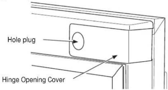
text_image
Hole plug Hinge Opening Cover- Remove hole plugs or screws from unit's new hinge locations (if applicable). Set aside.
-
Install the 2 hinge screws removed after the door was removed from the cabinet into the outermost holes on the new hinge side of the cabinet. Screw these in only about half way.
-
Remove the upper hinge from the door and move it to the door's opposite side, bottom location. Secure using the original screws.
NOTE: If door panel is attached, it must be removed to access hinge screws and to reverse the handle position.
- Remove the original lower door hinge and move it to the opposite side, upper location. Secure using original screws.
IMPORTANT: If installing a stainless steel door panel or custom panel, skip to INSTALLING THE DOOR PANEL section.
- Install pocket covers and hole plugs onto door.
- Place the keyhole slot on the hinge over the outermost screw, top and bottom, and slide the door onto the cabinet.
- Install the door to the cabinet using the original screws. Tighten all 4 screws.
IMPORTANT: In some situations the door can open too far and damage adjacent cabinets. To prevent this, insert a Stop Pin (in hardware packet) into the provided hole in the top and bottom hinges. Drive the pin into the hole until the head is flush with the hinge
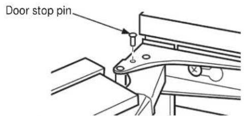
text_image
Door stop pin- Slide the hinge covers from the hardware packet over each hinge.
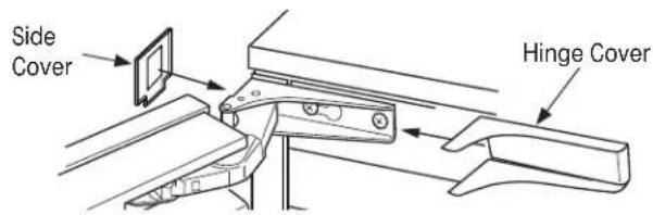
text_image
Side Cover Hinge Cover- Attach the side covers from the hardware packet over the hinge by peeling off the covering over the adhesive and placing it over the side of the hinge. NOTE: If the unit is being built-in a screw can be used to secure the unit to the cabinet in place of installing the side covers.
INSTALLING THE DOOR PANEL
The ice machine is supplied without a conventional door covering, allowing the attachment of a stainless steel door panel or a custom panel.
NOTE: If the door swing is to be changed, it needs to be done BEFORE attaching the door panel.
Door Panel
Finished stainless steel door panels with handles are available from GE Appliances for attachment to the ice machine. See Accessories on page 10.
A custom panel of wood or other material not exceeding 15 lbs can be used and must follow these guidelines: width: 14 7/8"
height: between 29 5/8" and 30 5/8"
thickness: 5/8" to 3/4"
For Custom Panel:
- Measure overall height of the cabinet opening where the ice machine will be installed (floor to bottom of the countertop edge).
- Determine desired toekick height (bottom of door to the floor). This can be equal to the adjacent cabinet's toekick height.
- The clearance between the countertop and the top of the ice machine should be at least 1/8".
- Subtract the toekick height and the clearance from the opening height to determine the height of your custom door panel.
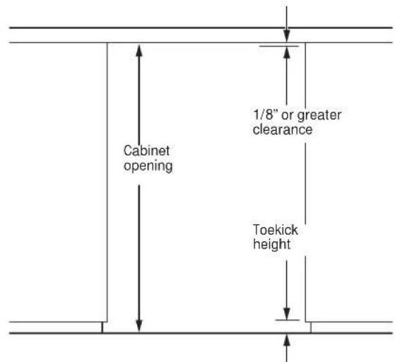
text_image
Cabinet opening 1/8" or greater clearance Toekick height- Cut the panel to the specified width and height.
-
Determine the top of the panel. Measure and mark hole locations.
-
Drill pilot holes on the back of the panel at your markings. Use a drill stop to prevent drilling through the panel.
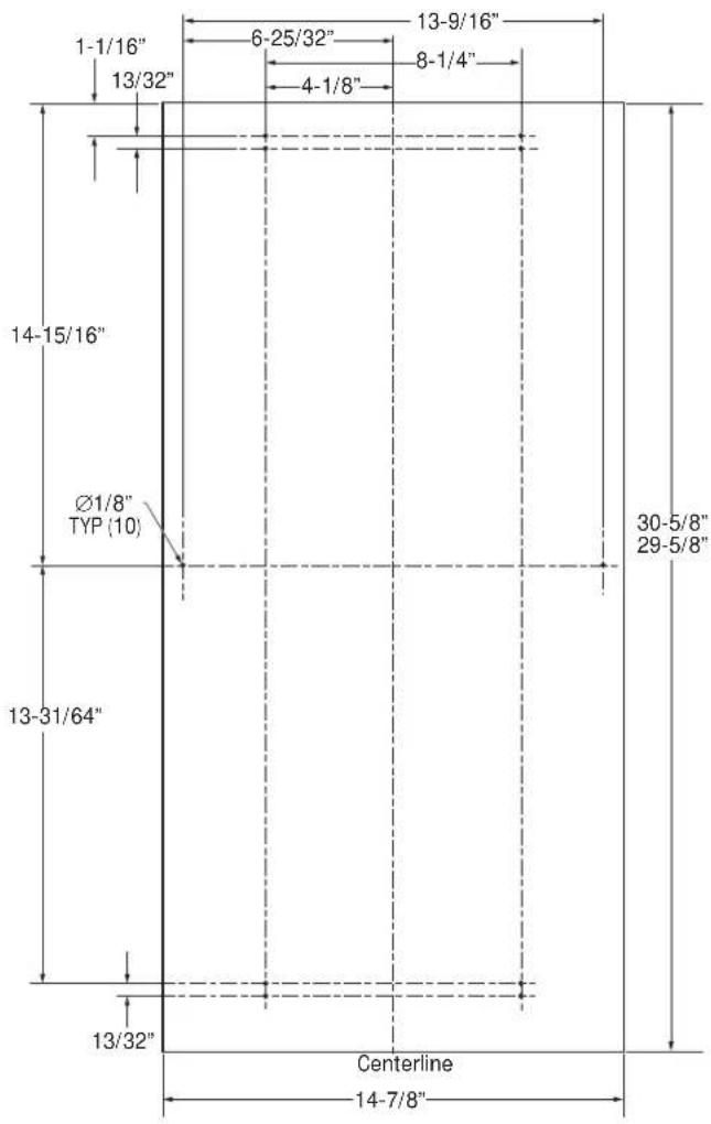
text_image
1-1/16" 13/32" 6-25/32" 4-1/8" 13-9/16" 8-1/4" 14-15/16" Ø1/8" TYP (10) 13-31/64" 30-5/8" 29-5/8" 13/32" Centerline 14-7/8"INSTALLING THE ICE MACHINE (Cont.)
INSTALLING THE DOOR PANEL (Cont)
If the door swing is going to be changed please complete prior to installing the door panel. See page 13.
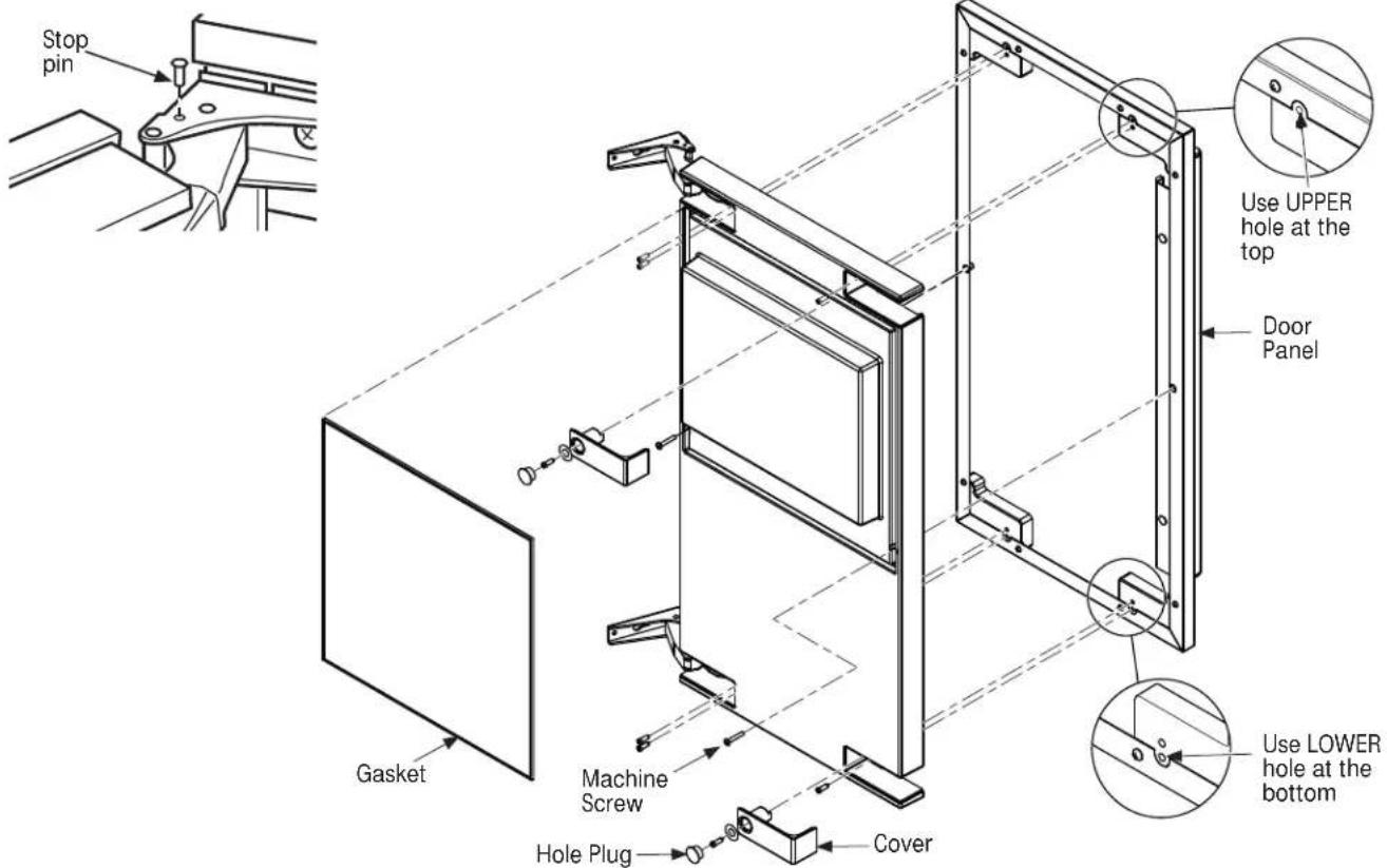
Attaching the Door Panel
The panel will be held on by 6 sheet metal screws and 2 machine screws.
- Remove the gasket from the inside of the door and retain for later use.
- Remove any plastic covering the stainless steel panel.
- Place the door panel onto the outside of the door and secure it with 2 machine screws in the left center and right center of the door.
- Fasten the panel to the door using the 6 sheet metal screws. In the hinge opening area opposite the hinge side, use the outermost screw holes only.
- Place the covers over the hinge opening areas and secure each cover to the door using a sheet metal screw and washer.
- Insert hole plug over screw installed in step 5.
- Return the gasket to its original position.
- Attach the door to the cabinet using the original screws.
IMPORTANT: In some situations the door can open too far and damage adjacent cabinets. To prevent this, insert a Stop Pin (in hardware packet) into the provided hole in the top and bottom hinges. Drive the pin into the hole until the head is flush with the hinge.
- Slide the hinge covers from the hardware packet over each hinge.
- Attach the side covers from the hardware packet over the hinge by peeling off the covering over the adhesive and placing it over the side of the hinge.
Note: If the unit is being built-in a screw can be used to secure the unit to the cabinet in place of installing the side covers.
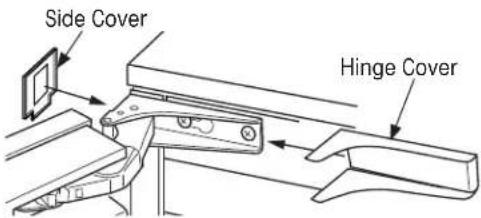
text_image
Side Cover Hinge Cover- Return the kickplate and front service panel to their original positions and attach to the cabinet using the original screws.
text_image
Stop pin Use UPPER hole at the top Door Panel Gasket Machine Screw Hole Plug Cover Use LOWER hole at the bottomPLUMBING
The recommended water supply tubing is 1/4" OD copper. Stainless steel flex or reinforced PCV tube may also be used. Install an easily accessible shut-off valve between the supply and the unit. This shut-off valve should not be installed behind the unit.
NOTE: Do not use self-piercing type valves.
- Remove the front service panel.
- Route the tubing through the right hole in the back to the inlet water solenoid valve inlet.
- Install a compression fitting on the tubing and connect to the inlet of the solenoid.
DRAIN PUMP
Drain Installation
A drain pump is available for this ice machine. The drain pump kit number is UPK3 and is available at www.GEApplianceparts.com or by calling 877-959-8688. In Canada visit www.GEAppliances.ca or call 800.561.3344.
GRAVITY DRAIN
Drain Installation

NOTICE
Restrictions in the drain system to
the machine will cause water to back up into the ice storage bin and melt the ice. Gravity drain tubing must be vented, have no kinks, and slope to the building drain. Air gaps are typically required by local codes.
- Place the ice machine in front of the installation opening. Adjust leveling legs to the approximate height. There are Leg Caps in the hardware packet that can snap onto the leveling legs if they are going to show when the unit is level.
- Remove the front service panel and the upper black panel.
NOTE: If the drain opening has been located in the floor under the base pan according to the pre-install specifications, follow steps 3-6 to drain the unit through the base. If not, proceed to 6.
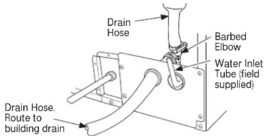
- Remove the clamp and barbed elbow and take off the plastic cover in the base pan below the drain hose.
- Connect a straight 5/8" barbed connector to the drain hose, securing with the supplied hose clamp.
-
Cut an 8"piece of 5/8" OD x 7/8" OD tygon (clear plastic) tubing. Slide one end of the tube onto the clamp, Leave the other end of the tube lying on the floor of the base pan until the unit is positioned over the floor drain.
-
Route the drain tube either a) Insert the drain tube through the base pan into the floor drain or b) Route the drain tube through the left hole in the lower back panel and connect to barbed elbow and secure with a clamp.
text_image
Drain Hose Barbed Elbow Water Inlet Tube (field supplied) Drain Hose, Route to building drain- Reinstall the upper back panel.
- Reinstall the service access panel. Level the unit.There are Leg Caps in the hardware packet that can snap onto the leveling legs if they are going to show when the unit is level.
Water Supply
The recommended water supply tubing is 1/4" OD copper. Stainless steel flex or reinforced PCV tube may also be used. Install an easily accessible shut-off valve between the supply and the unit. This shut-off valve should not be installed behind the unit.
The water connection is at the back of the cabinet. Connect using a compression fitting, one is supplied tied to the water inlet tube at the back of the cabinet.
When built in: Coil enough tubing behind the machine so it can be pushed into the cavity without kinking the tubing.
INSTALLATION
The ice machine is supplied with a power cord. Do not remove the grounding pin from the cord's plug. Do not use extension cords. Follow all codes. Connect the machine so its own 115v, 15amp circuit.
- If the electrical outlet for the ice maker is behind the unit, plug it into the unit.
- Position the unit in the installation opening.
- Turn on the water supply. Make sure that the icemaker is plugged in and the power is on.
- Slide the unit into the installation opening, paying special attention to water supply and drain connections. Do not kink!
- Pour a couple of quarts of water into the ice storage bin; on drain pump equipped machines the drain pump should start and water should pump out. Check for leaks.
- Replace the service access panel.
- Level the unit as needed.
Before you call for service...

Troubleshooting Tips
Save time and money! Review the charts on the following
pages first and you may not need to call for service.
| Problem Possible Causes What to Do | ||
| Ice cubes are incompletely formed | Scale on the ice making system | Clean the ice making system |
| Low capacity Restricted drain or standing | ng water in the bin | Clean the air cooled condenser fins. |
| Clean the ice making system. | ||
| Check the drain line for kinks | ||
| No ice | Switch is OFF | Press the ON/OFF button to turn the power on. |
| Electric breaker has been tripped Flip the electric breaker back on. | ||
| Water supply is low If the Check Water light is flashing Red, the water supply is low. The control system checks for water every 20 minutes. When the water supply is restored, the machine will automatically reset. | ||
| Time to Clean light is on | Clean the ice making system following directions in the Care and Cleaning section. | |
Noise
The ice machine is designed for quiet operation but will make some noise during the ice making cycle. During a freezing cycle, it is normal to hear the fan moving air and the water pump circulating water. Ice hitting the bin or ice in the bin can be heard during harvest.
If ice making noise is objectionable, an appliance grade timer can be added to the power supply. Set the timer to turn the machine off at the time(s) of day when the noise is the most objectionable.
Ice Machine Warranty.
For US Customers, all warranty service provided by our Factory Service Centers, or an authorized Customer Care® technician. To schedule service, visit us online at GEAppliances.com, or call 800.GE.CARES (800.432.2737). Please have serial number and model number available when calling for service. In Canada, call 800.561.3344.
Staple your receipt here. Proof of the original purchase date is needed to obtain service under the warranty.
For the Period of: GE Appliances Will Replace
| One YearFrom the date of the original purchase | Any part of the ice machine which fails due to a defect in materials or workmanship.During the limited one-year warranty, GE Appliances will also provide, free of charge, all labor and related service to replace the defective part. |
| Five YearsFrom the date of the original purchase | Any part of the sealed refrigeration system (the compressor, condenser, evaporator and all connecting tubing) which fails due to a defect in materials or workmanship.During the limited five-year sealed refrigerating system warranty, GE Appliances will also provide, free of charge, all labor and related service to replace the defective part in the sealed refrigerating system. |
What GE Appliances Will Not Cover:
■ Service trips to your home to teach you how to use the product.
- Improper installation, delivery or maintenance.
- Failure of the product if it is abused, misused, or used for other than the intended purpose or used commercially.
■ Replacement of house fuses or resetting of circuit breakers.
■ Damage caused after delivery.
■ Replacement of the light bulbs, if included.
■ Damage to the product caused by accident, fire, floods or acts of God.
■ Incidental or consequential damage caused by possible defects with this appliance.
■ Product not accessible to provide required service.
EXCLUSION OF IMPLIED WARRANTIES—Your sole and exclusive remedy is product repair as provided in this Limited Warranty. Any implied warranties, including the implied warranties of merchantability or fitness for a particular purpose, are limited to one year or the shortest period allowed by law.
For US Customers: This warranty is extended to the original purchaser and any succeeding owner for products purchased for home use within the USA. If the product is located in an area where service by a GE Appliances Authorized Servicer is not available, you may be responsible for a trip charge or you may be required to bring the product to an Authorized GE Appliances Service location for service. In Alaska, the warranty excludes the cost of shipping or service calls to your home.
Some states do not allow the exclusion or limitation of incidental or consequential damages. This warranty gives you specific legal rights, and you may also have other rights which vary from state to state. To know what your legal rights are, consult your local or state consumer affairs office or your state's Attorney General.
Warrantor: General Electric Company. Louisville, KY 40225
For Customers in Canada: This warranty is extended to the original purchaser and any succeeding owner for products purchased in Canada for home use within Canada. In-home warrant service will be provided in areas where it is available and deemed reasonable by Mabe to provide.
Warrantor Canada: MC Commercial, Burlington, Ontario, L7R 5B6
GE Appliances Website
In the U.S.: GEAppliances.com
Have a question or need assistance with your appliance? Try the GE Appliances Website 24 hours a day, any day of the year! You can also shop for more great GE Appliances products and take advantage of all our on-line support services designed for your convenience. In Canada: www.GEAppliances.ca
Schedule Service
In the U.S.: GEAppliances.com
Expert GE Appliances repair service is only one step away from your door. Get on-line and schedule your service at your convenience any day of the year! Or call 800.GE.CARES (800.432.2737) during normal business hours. In Canada, call 1.800.561.3344
Real Life Design Studio
In the U.S.: GEAppliances.com
GE Appliances supports the Universal Design concept—products, services and environments that can be used by people of all ages, sizes and capabilities. We recognize the need to design for a wide range of physical and mental abilities and impairments. For details of GE Appliances' Universal Design applications, including kitchen design ideas for people with disabilities, check out our Website today. For the hearing impaired, please call 800.TDD.GEAC (800.833.4322).
In Canada, contact: Manager, Consumer Relations, Mabe Canada Inc. Suite 310, 1 Factory Lane Moncton, N.B. E1C 9M3
Extended Warranties
In the U.S.: GEAppliances.com
Purchase a GE Applinaces extended warranty and learn about special discounts that are available while your warranty is still in effect. You can purchase it on-line anytime, or call 800.626.2224 during normal business hours. GE Appliances Consumer Home Services will still be there after your warranty expires. In Canada, call 1.888.261.2133
Parts and Accessories
In the U.S.: GEApplianceParts.com
Individuals qualified to service their own appliances can have parts or accessories sent directly to their homes (VISA, MasterCard and Discover cards are accepted). Order on-line today, 24 hours every day or by phone at 800.626.2002 during normal business hours.
Instructions contained in this manual cover procedures to be performed by any user. Other servicing generally should be referred to qualified service personnel. Caution must be exercised, since improper servicing may cause unsafe operation.
Customers in Canada should consult the yellow pages for the nearest Mabe service center, or call 1.800.661.1616.

Contact Us In the U.S.: GEAppliances.com
If you are not satisfied with the service you receive from GE Appliances, contact us on our Website with all the details including your phone number, or write to: General Manager, Customer Relations
GE Appliances, Appliance Park Louisville, KY 40225
In Canada: www.GEAppliances.ca, or write to: Director, Consumer Relations, Mabe Canada Inc. Suite 310, 1 Factory Lane Moncton, N.B. E1C 9M3
Register Your Appliance
In the U.S.: GEAppliances.com
Register your new appliance on-line—at your convenience! Timely product registration will allow for enhanced communication and prompt service under the terms of your warranty, should the need arise. You may also mail in the pre-printed registration card included in the packing material, or detach and c use the form in this Owner's Manual. In Canada: www.GEAppliances.ca
Installation instructions
text_image
Condenser surfaceNote: The bin is insulated and not refrigerated so the ice form will change in the storage bin as it is normal for the ice to melt.
IMPORTANT: Never keep anything in the ice storage bin that is not ice. Objects like wine or beer bottles are not only unsanitary, but the labels can slip off and plug up the drain.
IMPORTANT: Never allow the machine to operate without regular cleaning. The machine will last longer if it is kept clean. Regular cleaning should happen at least once per year, and preferably twice. Some water conditions will dictate even more frequent cleaning of the ice making section, and some carpets or pets will dictate more frequent cleaning of the condenser
Spécifications
text_image
3-7/8 PO TROU D'ACCES AU DRAIN DE PLANCHER 20-3/8 PO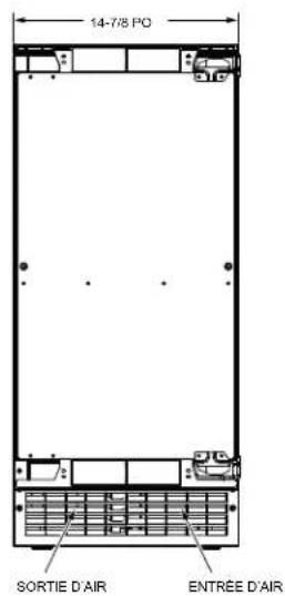
text_image
14-7/8 PO SORTIE D'AIR ENTRÉE D'AIR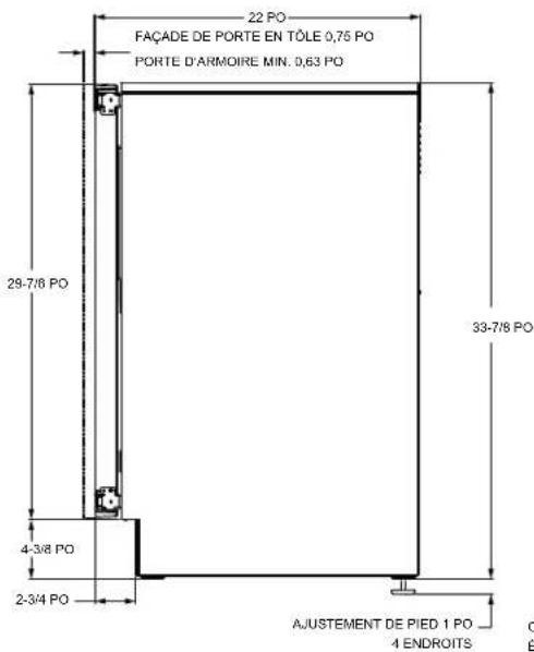
text_image
22 PO FAÇADE DE PORTE EN TÔLE 0,75 PO PORTE D'ARMOIRE MIN. 0,63 PO 28-7/8 PO 4-3/8 PO 2-3/4 PO 33-7/8 PO AJUSTEMENT DE PIED 1 PO 4 ENDROITS C É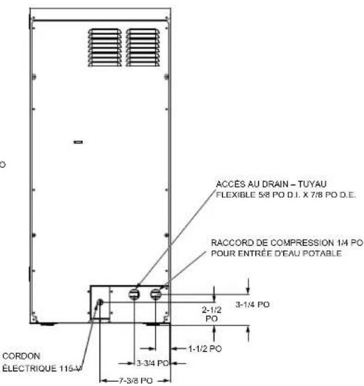
text_image
ACCÉS AU DRAIN - TUYAU FLEXIBLE 5/8 PO D.I. X 7/8 PO D.E. RACCORD DE COMPRESSION 1/4 PO POUR ENTRÉE D'EAU POTABLE 3-1/4 PO 2-1/2 PO 1-1/2 PO 3-3/4 PO 7-3/8 PO CORDON ÉLECTRIQUE 115-MINSTALLATION DE LA MACHINE À GLAÇONS (suite)
DIRECTION DE L'OUVERTURE DE PORTE
The ice machine is supplied with a power cord. Do not remove the grounding pin from the cord's plug. Do not use extension cords. Follow all codes. Connect the machine so its own 115v, 15amp circuit.
- If the electrical outlet for the ice maker is behind the unit, plug it into the unit.
- Position the unit in the installation opening.
- Turn on the water supply. Make sure that the icemaker is plugged in and the power is on.
- Slide the unit into the installation opening, paying special attention to water supply and drain connections. Do not kink!
- Pour a couple of quarts of water into the ice storage bin; on drain pump equipped machines the drain pump should start and water should pump out. Check for leaks.
- Replace the service access panel.
- Level the unit as needed.
Operating Instructions
Installation Instructions
natural_image
Technical line drawing of a mechanical assembly with no visible text or symbolsnatural_image
Simple line drawing of a mechanical component with a circular feature and a pointed tip (no text or symbols)Bloqueador de goma
text_image
1-1/16" 13/32" 6-25/32" 4-1/8" 13-9/16" 8-1/4" Ø1/8" TYP (10) 14-15/16" 13-31/64" 30-5/8" 29-5/8" 13/32" Línea central 14-7/8"natural_image
Illustration of a hand holding a rope with a pointer above a grid-patterned surface (no text or symbols)Warrantor: General Electric Company. Louisville, KY 40225
General Manager, Customer Relations GE Appliances, Appliance Park Louisville, KY 40225