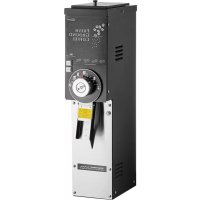
890 - Coffee machine Cecilware - Free user manual and instructions
Find the device manual for free 890 Cecilware in PDF.


| Product Type | Professional coffee grinder |
| Brand | Cecilware |
| Model | 890 |
| Dimensions (H x W x D) | 687 mm x 330 mm x 210 mm |
| Power supply | 120 V / 920 W / 8 A / 1 Ph |
| Hopper capacity | 3 lb (1.36 kg) for model 890BS, 5 lb (2.27 kg) for model 890T |
| Burr type | European hard alloy burrs |
| Grind adjustment | Rotary selector with fine adjustment screw |
| Features | Automatic stop when bag is removed, motor protection circuit breaker, shear pin protection |
| Safety | Circuit breaker, shear pin, automatic stop, grounding |
| Cleaning | Exterior washable with soapy water; grinding parts dry cleaned (stiff brush); food contact parts washable with soapy water |
| Spare parts | Burr set, shear pin, shear disk, grinding cover, etc. |
| Reparability | Burr replacement, shear pin, circuit breaker; technical support available |
| General information | Designed for moderate use; C-UL, US, ETL certified; note serial number |
Frequently Asked Questions - 890 Cecilware
User questions about 890 Cecilware
0 question about this device. Answer the ones you know or ask your own.
Ask a new question about this device
Download the instructions for your Coffee machine in PDF format for free! Find your manual 890 - Cecilware and take your electronic device back in hand. On this page are published all the documents necessary for the use of your device. 890 by Cecilware.
USER MANUAL 890 Cecilware
800 Series Coffee Grinders
Models 810, 835, 875, 890
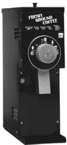
Model 810
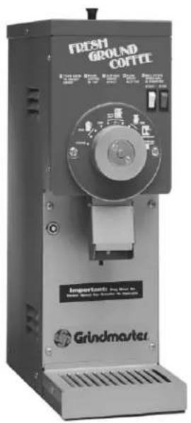
Model 835
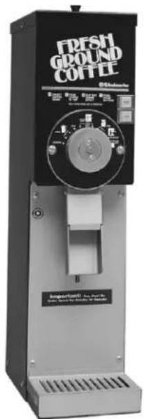
Model 875
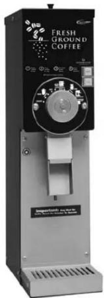
Model 890

cULus

cULus

cULus

cULus
Table of Contents
| Specifications......2 |
| Safety Information......3 |
| Installation......3 |
| Operation......4 |
| Cleaning & Maintenance......5 |
| Troubleshooting Guide......6 |
| Parts Diagram and List ......7 |
| Wiring Diagram......10 |
Thank you for purchasing this quality coffee grinder. For your safety and the safety of others, read all warnings and the operator's manual before installing or using the product. Properly instruct all operators.
Keep training records. For future reference, record serial number here:
Grindmaster-Cecilwareprovides the industry's BEST warranty. Visit gmcw.com for warranty terms and conditions.
Specifications
| Model Description Electrical | ||
| 810S | Medium duty grinder - 1.5 lbs hopper.C-UL US, ETL Sanitation Certification | 120V / 920 W / 8A / 1 Ph |
| 835S | Medium duty grinder - 1.5 lbs hopper.C-UL US, ETL Sanitation Certification | 120V / 920 W / 8A / 1 Ph |
| 875S | Medium duty grinder - 3 lbs hopper.C-UL US, ETL Sanitation Certification | 120V / 920 W / 8A / 1 Ph |
| 890BS | Medium duty grinder with European slicing burrs- 3 lbs. hopper.C-UL US, ETL Sanitation Certification | 120V / 920 W / 8A / 1 Ph |
| 890T | Medium duty grinder with European slicing burrs- 5 lbs. hopper.C-UL US, ETL Sanitation Certification | 120V / 920 W / 8A / 1 Ph |
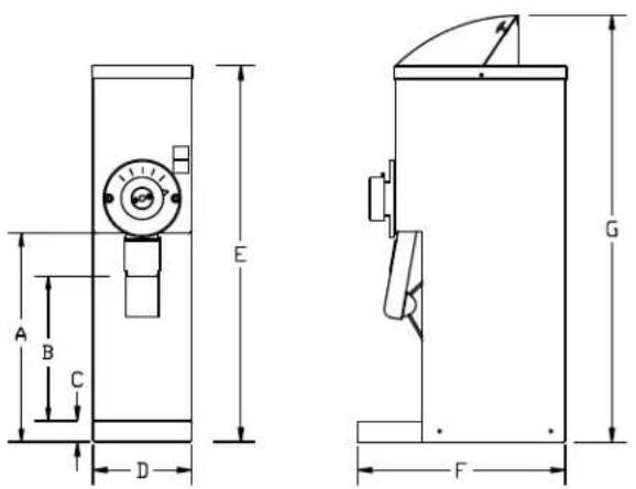
| Dimensions (Inches) | |||||||
| A | B | C | D | E | F | G | |
| 810 | 11 1/2 | 8 | - | 7 | 21 1/4 | 12 1/2 | 25 |
| 835 | 10 | 8 1/4 | 1 1/2 | 7 | 21 1/4 | 15 | 25 |
| 875 | 13 | 8 1/4 | 1 1/2 | 7 | 27 | 15 | 30 3/4 |
| 890 | 13 | 8 1/4 | 1 1/2 | 7 | 27 | 15 | 30 3/4 |
| 890T | 7 | 31 1/4 | 14 | 35 | |||
Safety Information
Important Safety Information

This is the safety alert symbol. It is used to alert you to potential personal injury hazards. Obey all safety messages that follow this symbol to avoid possible injury or death.
For your safety and the safety of others, read all warnings and the operator's manual before installing or using the product.
DANGER: This term warns the user of imminent hazard that will result in serious injury or death.
WARNING: This term refers to a potential hazard or unsafe practice, which could result in serious injury or death.
CAUTION: This term refers to a potential hazard or unsafe practice, which could result in minor or moderate injury.
NOTICE: This term refers to information that needs special attention or must be fully understood.
WARNING
- Product must be attached to a three wire 120V 15 AMP receptacle (export units - 230V 16 AMP).
- Do not deform plug or cord.
- Follow national and local electrical codes.
- Do not use near combustibles.
- Use only on a circuit load that is properly protected and capable of the rated load.
•Always unplug unit from power supply before servicing or cleaning.
FAILURE TO COMPLY RISKS PERSONAL INJURY, SHOCK HAZARD, FIRE, OR DAMAGE TO EQUIPMENT.
CAUTION
Personal injury hazard. Keep fingers, hands, and foreign objects out of hopper or chute opening. Model 890T must be bolted to the counter to prevent possible bodily injury from overturning.
NOTICE
Never connect to an overloaded circuit or to an extension cord, otherwise serious damage to the motor may result.
Installation
⚠️ CAUTION: Risk of bodily injury due to tipping. Use care when installing Model 890T.
NOTICE: It is essential that full voltage and amperage always be available as it takes full power to grind coffee.
Please read this manual before operating the grinder.
- Carefully remove grinder from carton.
- Place grinder in position on shelf, counter or other flat surface.
- (Model 890T only). Using (4) provided 5/16"-18 x 1 1/2" bolts, washers, and nuts, attach grinder securely to counter.
- Plug grinder into the specified power source. (Check rating plate on back of unit for voltage and amperage requirements.) Do not use an extension cord.
- Fill hopper with whole bean coffee.
- Grind a small amount of whole bean coffee
following operating instructions as described in this manual
- If there is any problem, consult the Troubleshooting Guide in this manual, (also on back of grinder.)
If you need help, call Grindmaster-Cecilware Technical Service Department for help, (502) 425-4776 or (800) 695-4500 (USA & Canada only) 8 AM - 6 PM EST.
Prior authorization must be obtained from Grindmaster-Cecilware for all warranty claims.
Operation
Your new coffee grinder is easy to operate and maintain. Before you place it in service, please have all personnel familiarize themselves with these instructions. Keep this manual in a convenient place for ready reference.
How to Operate
- Turn the selector knob to the desired grind setting.
- Fill the hopper with the desired type and amount of whole bean coffee. Close the lid.
- Place the bag underneath the spout.
- Press the start button. *810 model - Press the grinder switch to the ON position.
- The grinder will automatically stop when the bag is removed.**
* 810 model - Once coffee is ground, press the grinder switch to the off position or grinder will continuously run.
** On models 835 and 875 the stop button may be pressed after the grinder has completed grinding. - Remove bag from coffee spout once coffee is ground.
Grinds
Before shipment, this grinder has been tested with coffee and has been accurately adjusted to deliver ground coffee to normal auto drip specifications.
The Grinding Burrs are made of an extremely hard and wear resistant material. From time to time, grind adjustments (see following instructions) may be necessary. If the grind runs coarser than expected after normal adjustment and the grind time has increased, the burrs may have excess wear and should be replaced. New burrs should always be installed as a pair, never one or the other, as they are accurately ground and lapped in pairs. Old burrs cannot be resharpened.
Grind Adjustment
Tools required: Phillips screwdriver
Large blade screwdriver
Pliers
- Remove all coffee from the hopper.
- Set selector knob to the finest setting (Espresso or Turkish) depending on the model.
- Loosen both knob retainer screws in selector knob one turn only.
- While pressing the bag switch, located behind the spout, press the start button so that the grinder will run during
adjustment.
*810 model - Press the on or start button so that the grinder will run during adjustment.
- With the grinder still running, turn the adjusting screw in the center of the selector knob slowly to the right until a slight chirping noise is heard. Immediately turn the adjusting screw to the left until chirping noise stops. This is the finest grind obtainable.
- Tighten both of the knob retainer screws. Once the finest grind has been set, the other grind settings will automatically set correctly.
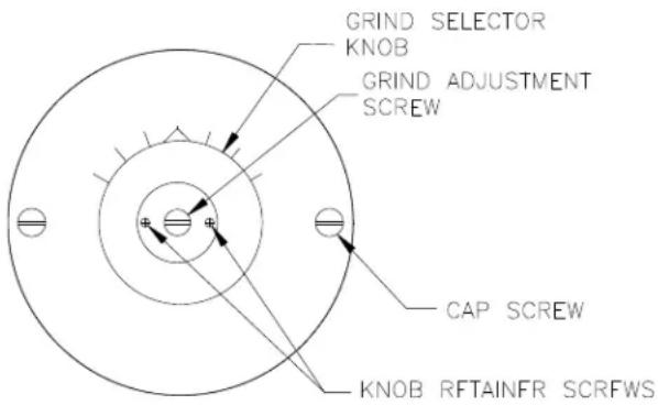
7. Press the stop or off button.
NOTICE: Always be sure the grinding burrs are not touching while the machine is running on the ESPRESSO/TURKISH setting. Otherwise serious damage to the motor may result.
Protection
This grinder is equipped with both a circuit breaker and a shear disc or shear pin to protect motor and burrs.
Circuit Breaker
This grinder is equipped with a circuit breaker to protect the motor from overloading. When the circuit breaker trips, the reset button will pop out approximately 1/4" which stops the power to the grinder. The reset button is located on the front panel of the Model 810, 835 and 875. To reset the circuit breaker, wait two minutes then push in the reset button. You will hear a click as it resets. If the grinder does not operate after resetting the circuit breaker, there may be an obstruction in the grinding mechanism that is stalling the motor. Turn the grind selector knob all the way to the left. Try restarting the grinder. If the circuit breaker "trips" again, the obstruction was not able to pass. In this case, the Grinder Head should be cleaned out as described in the Shear Disc Replacement section of this manual.
Cleaning & Maintenance
Cleaning Instructions
NOTICE: The person cleaning the parts should do so with clean hands.
The outside of the machine can be cleaned with warm soapy water and a damp cloth.
Grinding parts should be cleaned with a stiff brush or dry cloth. DO NOT USE WATER. See Shear Disc Replacement for instructions on assembling and disassembling grinder parts. Before reassembling, wipe motor shaft with dry cloth.
All other parts that are in contact with food must be washed with warm soapy water, rinsed, and air-dried.
Lubrication
None required.
Shear Disc Replacement
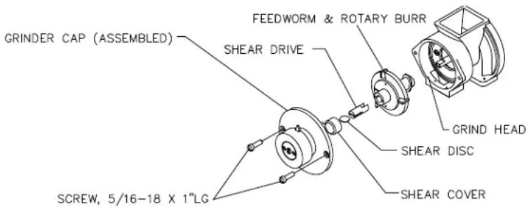
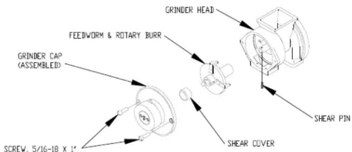
If the motor should run and no coffee is dispensed, the Shear Disc may have sheared. Should this occur, perform the following operations in the sequence given (refer to following drawing).
Tools Required: Slotted Screwdriver
Pliers
⚠ WARNING: Unplug grinder to prevent electrical shock.
- Remove all of the coffee beans from the hopper.
- Remove the Grinder Cap by taking out the 2 Cap Screws.
- (Model 890) Turn Feedworm Assembly such that the slot in the assembly is vertical then
push inward to release the Shear Pin.
- Pull out the Rotary Burr and Feedworm Assembly. Clean out the Grinder Head, removing all coffee particles from inside of the Grinder Head and the Grinder Cap so that it can be reset properly.
- Check that no obstruction has been caught on the surface of the teeth of either burr. Remove the Shear Cover and broken pieces of the Shear Disc or Shear Pin. You are now ready to reassemble the grinder mechanism.
- Slide the Rotary Burr and Feedworm Assembly onto the Drive Shaft. (Model 810, 835, 875) Insert the shear drive so that the Motor Shaft tongue engages into the shear drive notch.
- (Model 810, 835, 875) Insert a new Shear Disc by aligning the slot in the Shear Drive with the slot in the hub of the Feedworm. (Model 890) Align slot in Feedworm Assembly with the hole in the motor shaft. Install new Shear Pin.
- Reassemble the Shear Cover and Grinder Cap. Make certain the Grinder Cap is screwed on tight and is sealed properly against the head and not tilted or misaligned. Otherwise, a proper grind cannot be obtained.
- Your grinder is now ready to grind.
Troubleshooting Guide
Before you call for help, please read the following:
WARNING: Unplug power cord from outlet before cleaning or servicing your grinder.
| Problem Possible Cause Solution | ||
| Grinder will not start when Bag not under spout. Place bag underneath spout. START button is pushed Plug not in outlet properly. Install plug in outlet. No power to outlet. Check outlet with lamp or radio to verify outlet has power. | ||
| Grinder runs or hums but no coffee is dispensed button until you hear a click. | Circuit breaker has tripped. | Reset circuit breaker by pushing in reset |
| Shear disc is broken. Replace shear disc. | See Shear Disc Replacement or instructions on back of grinder. | |
| Obstruction in opening to grinding chamber. | Unplug unit. Empty beans out of hopper and clear obstructions. See Shear Disc Replacement for disassembly and assembly instructions. | |
| Excessive amount of coffee chaff flying about | Defective chaff mixer spring. | If bent, broken, or missing, replace spring. If stuck open with coffee, clean out coffee to free spring. |
| Outlet not properly grounded. | Check power cord end and outlet for proper ground. | |
| Static electricity. | Tighten all nuts, bolts, and screws and verify outlet is grounded. | |
| Circuit breaker continuously trips | Insufficient amperage due to use of extension cord. Insufficient amperage due to overloaded line. Grind setting needs adjustment. | Plug unit directly into outlet. Do not use. extension cord. Designate single line for grinder. Do not use multi-outlet box. Adjust grind to coarser setting (see Grind Adjustment). |
If you still need help, call Grindmaster-Cecilware Technical Service Department, (502) 425-4776 or (800) 695-4500 (USA & Canada only) (Monday through Friday 8 AM - 6 PM EST). Please have the model and serial number ready so that accurate information can be given.
Prior authorization must be obtained from Grindmaster-Cecilware for all warranty claims.
Grindmaster-Cecilware provides the industry's BEST warranty. Visit our website at GMCW.com for warranty terms and conditions.
Parts Diagram and List
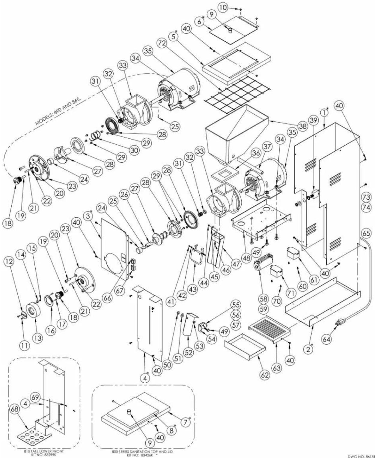
800 SERIES EXPLODED VIEW
PART NUMBERS INDICATED BY AN ASTERISK (*) ARE PAINTED COMPONENTS AND COLOR MUST BE SPECIFIED WHEN ORDERING.
NOTE: REFER TO THE PART NUMBER SHEET ON THE FOLLOWING PAGE WHEN ORDERING.
Parts Diagram and List (continued)
800 Series
| Item # DESCRIPTION 120V GROCERY GRINDER PART NUMBERS 230V GROCERY GRINDER PART NUMBERS | |||||||||||||
| 810-BS | 835-BS | 875-RS | 890-BS | 890-B-T | 810E-BG | 835-B-230VG | 835-R-230VG | 835-R-230VS | 875-B-230V | 875-R-230V | 890E-BG | ||
| 1 * | Casing, grocery 83332 * 83362* | 82356* | 83332 * 83332 * 83362 * | ||||||||||
| 2 * | Base 83302 * 83321 * 82355* | 83302 * 83321 * 83321 * | |||||||||||
| 3 * | Front panel 83316 * 83301 * 83363 * | 82362* 83316 * 83301 * 83363 * | |||||||||||
| 4 * | Lower front | 83305 * | 80072 | 80073 | 82360 | 83305 * | 80072 | 80073 | |||||
| 5 * | Top, bifold lid | - | 83308BK or 88308RK | - | |||||||||
| 6 * | Lid, bifold hinge | - | 88704BK or 88704RK | - | |||||||||
| 7 * | Top, 800 series sanitation | 83451BK or 83451RK | - | 83451 * | |||||||||
| 8 * | Lid, 800 series sanitation | 83450BK or 83450RK | - | 83450 * | |||||||||
| 9 | Knob, lid | 86223 | 86246 | 86223 | 86246 | ||||||||
| 10 | Screw, #8 x 1/4 ph tr hd | ||||||||||||
| 11 | Screw, #8 x 3/8" sl ovl | 86914 | 86914 | ||||||||||
| 12 | Plate, knob retainer | 82024 | 82024 | ||||||||||
| 13 | Knob, grind select | 82022 | 82022 | ||||||||||
| 14 | Pointer, knob | 88027 | 88027 | ||||||||||
| 15 | Screw, #6-32 x 1/4" | 86866 | 86866 | ||||||||||
| 16 | Plate, detent | 83361 | 82025 | 83361 | 82025 | ||||||||
| 17 | Screw, #8-32 x 1/4" | 86224 | 86224 | ||||||||||
| 18 | Screw, grind adjust | 82023 | 86434 | 82023 | 86434 | ||||||||
| 19 | Pin, grind adjust | 71298 | 71298 | ||||||||||
| 20 | Screw, 5/16-18 x 1" | 86887 | 86887 | ||||||||||
| 21 | Plunger, detent | 83318 | 83318 | ||||||||||
| 22 | Spring, detent | 83443 | 83443 | ||||||||||
| 23 | Grinder cap | 82021 | 86439 | 82021 | 86439 | ||||||||
| 24 | Cover, shear | 86355 | 86355 | ||||||||||
| 25 | Disc, shear (890 - Shear pin) | 86123 | 86620 | 86123 | 86620 | ||||||||
| 26 | Drive, shear | 86154 | - | 86154 | - | ||||||||
| 27 | Feedworm | 85188 | 86468 | 85188 | 86468 | ||||||||
| 28 | Burr set | 85281W | 86430 | 85281W | 86430 | ||||||||
| 29 | Screw, #10-32 x 5/16" | 350-00014 | 350-00014 | ||||||||||
| 30 | Feedworm spring | - | 86432 | - | 86432 | ||||||||
| 31 | Tension spring | 86118 | 86438 | 86118 | 86438 | ||||||||
| 32 | Thrust collar | 86304 | - | 86304 | - | ||||||||
| 33 | Grinder head | 84171S | 84172 | 86435 | 84171S | 84172 | 86435 | ||||||
| 34 | Nut, 1/4-20 cage | 86864 | 86864 | ||||||||||
| 35 | Motor, 1/2hp 120VAC 60Hz [230VAC 60Hz] | 86419 | 86581 | [86421] | 86581 | ||||||||
| 36 | Gasket, hopper | 88211 | 88211 | ||||||||||
| 37 | Finger guard | 83324 | 83324 | ||||||||||
| 38 | Hopper | 83356 | 88280 | 82365 | 83356 | 88280 | |||||||
| 39 | Circuit breaker, 10amp for 120VAC [5amp for 230VAC] | 86618 | [83107] | ||||||||||
| 40 | Screw, #10 x 1/2", sems, tr ph | 86868 | 86868 | ||||||||||
| 41 | Screw, spout flap | - | 60288 | - | 60288 | ||||||||
| 42 | Eyelet, 0.162 ID, rolled edge | - | 82039 | - | 82039 | ||||||||
Parts Diagram and List (continued)
800 Series
| Item # DESCRIPTION | 120V GROCERY GRINDER PART NUMBERS | 230V GROCERY GRINDER PART NUMBERS | |||||||||||
| 810-BS | 835-BS | 875-BS & 875-RS | 890-BS | 890-B-T | 810E-BG | 835-B-230VG | 835-R-230VG | 835-R-230VS | 875-B-230V | 875-R-230V | 890E-BG | ||
| 43 Spout flap - 82036 - 82036 | |||||||||||||
| 44 Screw, chaff spring 07023-01 | 86806 07023-04 86806 | ||||||||||||
| 45 Chaff spring 84154 82026 84154 82026 | 54 82026 | ||||||||||||
| 46 Screw, #8-32 x 3/8" 82124 82124 | |||||||||||||
| 47 | Spout | 88033 | 80088 | 82019 | 88033 | 80088 | 82019 | ||||||
| 48 | Motor shelf | 83334 | 83334G | 83334 | 83334G | 83334 | 83334 | 83334 | 83334G | ||||
| 49 Bolt, 1/4-20 x 5/8" | 86872 86872 | ||||||||||||
| 50 | Nut, 1/4-20 Nylon | - | 60007 | 87049 | - | 87049 | 60007 | ||||||
| 51 Bushing, spacer | - 83253 - 83253 | ||||||||||||
| 52 Bag, actuator | - 80084 - 80084 | ||||||||||||
| 53 Bushing, flanged | - 83252 - 83252 | ||||||||||||
| 54 Bracket, switch | - 83250 - 83250 | ||||||||||||
| 55 Switch, micro | - 80083 - 80083 | ||||||||||||
| 56 | Screw, #4-40 x 5/8" sl bd hd | - 8692 | 8 - 86928 | ||||||||||
| 57 Nut, 4-40 hex | - 86929 - 86929 | ||||||||||||
| 58 | Capacitor, 120VAC 60Hz [230VAC 50Hz] | 86144 | [86179] | ||||||||||
| 59 Screw, #8-32 x 3/8" 86874 86874 | |||||||||||||
| 60 Screw, #8-32 x 1/4" | - | - | |||||||||||
| 61 | Relay, 120VAC [Relay, 230VAC] | - 8530 | 3 - [85275] | [83 106] | |||||||||
| 62 Tidy tray drawer | - 83323 - 83323 | ||||||||||||
| 63 Tidy tray cover | - 83322 - 83322 | ||||||||||||
| 64 | Power cord, standard 120VAC [1.5MM CE] | 86222 | [61453] | ||||||||||
| 65 | Strain relief, standard cord | 86071 86071 | |||||||||||
| 66 | Switch, start | 70449 | 70445 | 88056 | 88056 | 70449 | 70445 | 88056 | |||||
| 67 | Switch, stop | - | 83327 | 88057 | - | 83327 | 88057 | ||||||
| 70 Screw, #6-32 x 1/4", SS | - 86993 | ||||||||||||
| 71 | Relay, Motor Start, 230VAC | - | 86424 | ||||||||||
| 72 Finger guard | - | - 83297 | |||||||||||
| 73 | Screw, #8-32 x 1/2", Ground | 86867 86867 | |||||||||||
| 74 Nut, #8-32, KEPS | 86810 | 86810 | 86810 | ||||||||||
| 77 Harness, wiring | 83341 82029 | 84143 82029 | |||||||||||
| 78 Harness, bag switch | - 80086 - 80086 | ||||||||||||
Wiring Diagram
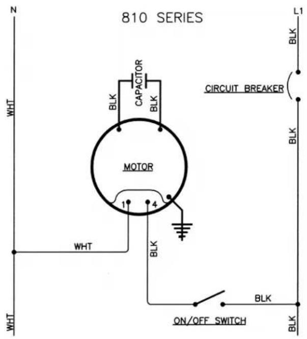
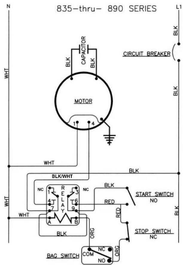
800 Series 120V Wiring Diagrams
Wiring Diagram (continued)
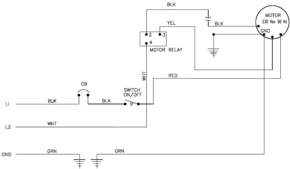
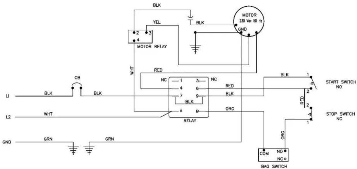
800 Series 230V, 50Hz Wiring Diagrams
MODEL 810 - 230V, 50HZ WIRING DIAGRAM
MODEL 835, 875, 890 - 230V, 50HZ WIRING DIAGRAM
Grindmaster-Cecilware
4003 Collins Lane, Louisville, KY 40245 USA
Phone: 502.425.4776 Toll Free: 800.695.4500
Fax: 502.425.4664
Web: gmcw.com Email: info@gmcw.com
©1995 Grindmaster-Cecilware
Printed in USA

Grindmaster Cecilware
1015 Form # GR-380-18
Part # 390-00052
MOULINS À CAFÉ SÉRIE 800
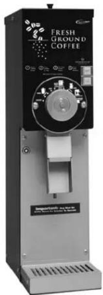
Modèle 875
Grindmaster-Cecilware
4003 Collins Lane, Louisville, KY 40245 USA
Web: gmcw.com Email: info@gmcw.com
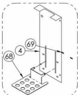
810 HAUT - PARTIE AVANT
INFÉRIEURE, KIT NO. 83299K*
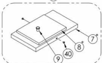
SÉRIE 800 – HAUT ET COUVERCLE ELT,
KIT NO. 83426K*
DWG NO. 86151
Grindmaster-Cecilware
4003 Collins Lane, Louisville, KY 40245 USA
Web: gmcw.com Email: info@gmcw.com
©1995 Grindmaster-Cecilware
Imprimé aux USA

Grindmaster Cecilware
1015 Formulaire # GR-380-18
Elément # 390-00052

- Series Coffee Grinders
- Safety Information
- Important Safety Information
- WARNING
- CAUTION
- NOTICE
- Installation
- Operation
- How to Operate
- Grinds
- Grind Adjustment
- Press the stop or off button.
- Protection
- Circuit Breaker
- Cleaning & Maintenance
- Cleaning Instructions
- Lubrication
- Shear Disc Replacement
- Troubleshooting Guide
- Parts Diagram and List
- SERIES EXPLODED VIEW
- Parts Diagram and List (continued)
- Series
- Wiring Diagram
- Series 120V Wiring Diagrams
- Wiring Diagram (continued)
- MOULINS À CAFÉ SÉRIE 800
- Grindmaster-Cecilware
Brand : Cecilware
Model : 890
Category : Coffee machine