
KMC48BI - Range hood BERTAZZONI - Free user manual and instructions
Find the device manual for free KMC48BI BERTAZZONI in PDF.
| Brand | Bertazzoni |
| Model | KMC48BI |
| Product Type | Built-in or chimney range hood |
| Width | 48 inches (121.9 cm) |
| Depth | Approximately 20 inches (50.8 cm) |
| Minimum Height Above Cooktop | 24 inches (61 cm) for electric cooktop, 30 inches (76 cm) for gas |
| Power Supply | 120 V, 60 Hz, dedicated 15 A circuit with time delay fuse |
| Motor Power | Not specified (estimated: around 600 CFM) |
| Speeds | 4 speeds (1, 2, 3, Intensive) |
| Lighting | Integrated LED, adjustable intensity (full and reduced) |
| Remote Control | Yes, with CR2032 battery (not included) |
| Special Functions | 24h function, 30 min delayed shutoff, filter saturation alarm |
| Exhaust Type | Ducted to outside or recirculation with charcoal filter kit (optional) |
| Duct Diameter | 6 inches (15.2 cm) |
| Grease Filters | Metal, dishwasher safe, clean every 2 months |
| Charcoal Filter | Active, replace every 4 months (optional accessory) |
| Warranty | 2 years limited (parts and labor) |
| Country of Manufacture | Italy (Bertazzoni brand) |
| Safety Standards | UL compliant, grounding required |
Frequently Asked Questions - KMC48BI BERTAZZONI
User questions about KMC48BI BERTAZZONI
0 question about this device. Answer the ones you know or ask your own.
Ask a new question about this device
Download the instructions for your Range hood in PDF format for free! Find your manual KMC48BI - BERTAZZONI and take your electronic device back in hand. On this page are published all the documents necessary for the use of your device. KMC48BI by BERTAZZONI.
USER MANUAL KMC48BI BERTAZZONI
natural_image
Technical line drawing of three mechanical components with no visible text or symbolsInstallation Instructions Use and Care Information
| KMC30X | KMC36X | KMC48X |
| KMC30BI | KMC36BI | KMC48BI |
| KMC30NE | KMC36NE | KMC48NE |
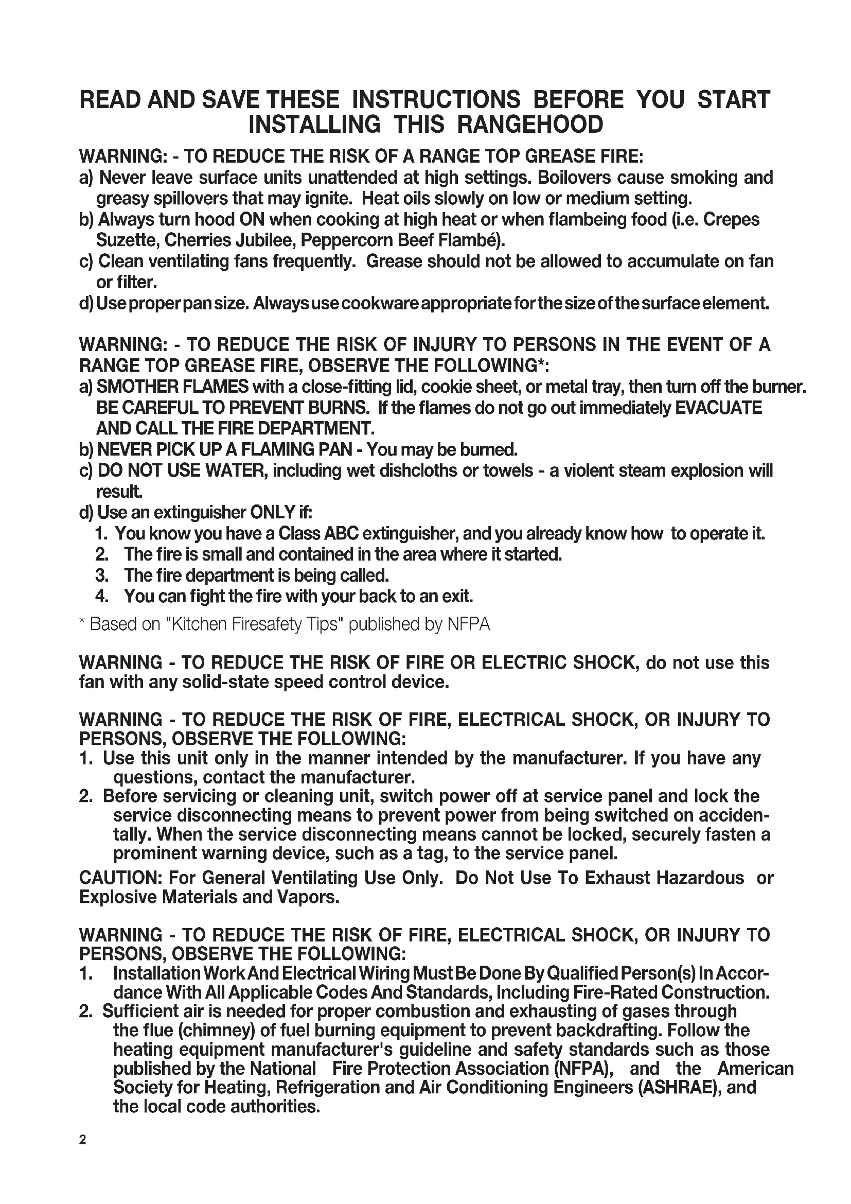
READ AND SAVE THESE INSTRUCTIONS BEFORE YOU START INSTALLING THIS RANGEHOOD
WARNING: - TO REDUCE THE RISK OF A RANGE TOP GREASE FIRE:
a) Never leave surface units unattended at high settings. Boilovers cause smoking and greasy spillovers that may ignite. Heat oils slowly on low or medium setting.
b) Always turn hood ON when cooking at high heat or when flambeing food (i.e. Crepes Suzette, Cherries Jubilee, Peppercorn Beef Flambé).
c) Clean ventilating fans frequently. Grease should not be allowed to accumulate on fan or filter.
d) Use proper pan size. Always use cookware appropriate for the size of the surface element.
WARNING: - TO REDUCE THE RISK OF INJURY TO PERSONS IN THE EVENT OF A RANGE TOP GREASE FIRE, OBSERVE THE FOLLOWING*:
a) SMOTHER FLAMES with a close-fitting lid, cookie sheet, or metal tray, then turn off the burner. BE CAREFUL TO PREVENT BURNS. If the flames do not go out immediately EVACUATE AND CALL THE FIRE DEPARTMENT.
b) NEVER PICK UP A FLAMING PAN - You may be burned.
c) DO NOT USE WATER, including wet dishcloths or towels - a violent steam explosion will result.
d) Use an extinguisher ONLY if:
1. You know you have a Class ABC extinguisher, and you already know how to operate it.
2. The fire is small and contained in the area where it started.
3. The fire department is being called.
4. You can fight the fire with your back to an exit.
* Based on "Kitchen Firesafety Tips" published by NFPA
WARNING - TO REDUCE THE RISK OF FIRE OR ELECTRIC SHOCK, do not use this fan with any solid-state speed control device.
WARNING - TO REDUCE THE RISK OF FIRE, ELECTRICAL SHOCK, OR INJURY TO PERSONS, OBSERVE THE FOLLOWING:
- Use this unit only in the manner intended by the manufacturer. If you have any questions, contact the manufacturer.
- Before servicing or cleaning unit, switch power off at service panel and lock the service disconnecting means to prevent power from being switched on accidentally. When the service disconnecting means cannot be locked, securely fasten a prominent warning device, such as a tag, to the service panel.
CAUTION: For General Ventilating Use Only. Do Not Use To Exhaust Hazardous or Explosive Materials and Vapors.
WARNING - TO REDUCE THE RISK OF FIRE, ELECTRICAL SHOCK, OR INJURY TO PERSONS, OBSERVE THE FOLLOWING:
- Installation Work And Electrical Wiring Must Be Done By Qualified Person(s) In Accordance With All Applicable Codes And Standards, Including Fire-Rated Construction.
-
Sufficient air is needed for proper combustion and exhausting of gases through the flue (chimney) of fuel burning equipment to prevent backdrafting. Follow the heating equipment manufacturer's guideline and safety standards such as those published by the National Fire Protection Association (NFPA), and the American Society for Heating, Refrigeration and Air Conditioning Engineers (ASHRAE), and the local code authorities.
-
When cutting or drilling into wall or ceiling, do not damage electrical wiring and other hidden utilities.
-
Ducted fans must always be vented to the outdoors.
ALL WALL AND FLOOR OPENINGS WHERE THE RANGEHOOD
IS INSTALLED MUST BE SEALED.
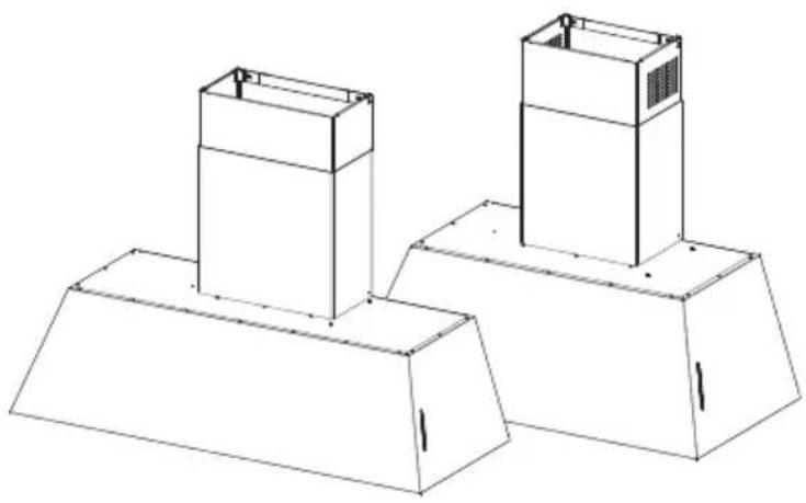
This rangehood requires at least 24" of clearance between the bottom of the rangehood and the cooking surface or countertop. This hood has been approved by UL at this distance from the cooktop. This minimum clearance may be higher depending on local building codes. For gas cooktops and combination ranges, a minimum of 30" is recommended and may be required.
Overhead cabinets on both sides of this unit must be a minimum of 18" above the cooking surface or countertop. Consult the cooktop or range installation instructions given by the manufacturer before making any cutouts.
MOBILE HOME INSTALLATION The installation of this rangehood must conform to the Manufactured Home Construction and Safety Standards, Title 24 CFR, Part 3280 (formerly Federal Standard for Mobile Home Construction and Safety, Title 24, HUD, Part 280). See Electrical Requirements.
VENTING REQUIREMENTS
Determine which venting method is best for your application. Ductwork can extend either through the wall or the roof.
The length of the ductwork and the number of elbows should be kept to a minimum to provide efficient performance. The size of the ductwork should be uniform. Do not install two elbows together. Use duct tape to seal all joints in the ductwork system. Use caulking to seal exterior wall or floor opening around the cap.
Flexible ductwork is not recommended. Flexible ductwork creates back pressure and air turbulence that greatly reduces performance.
Make sure there is proper clearance within the wall or floor for exhaust duct before making cutouts. Do not cut a joist or stud unless absolutely necessary. If a joist or stud must be cut, then a supporting frame must be constructed.
WARNING - To Reduce The Risk Of Fire, Use Only Metal Ductwork.
CAUTION - To reduce risk of fire and to properly exhaust air, be sure to duct air outside – Do not vent exhaust air into spaces within walls or ceilings or into attics, crawl spaces, or garages.
Cold Weather installations
An additional back draft damper should be installed to minimize backward cold air flow and a nonmetallic thermal break should be installed to minimize conduction of outside temperatures as part of the vent system. The damper should be on the cold air side of the thermal break. The break should be as close as possible to where the vent system enters the heated portion of the house.

WARNING
- Venting system MUST terminate outside the home.
- DO NOT terminate the ductwork in an attic or other enclosed space.
- DO NOT use 4" laundry-type wall caps.
- Flexible-type ductwork is not recommended.
- DO NOT obstruct the flow of combustion and ventilation air.
- Failure to follow venting requirements may result in a fire.
ELECTRICAL REQUIREMENTS
A 120 volt, 60 Hz AC-only electrical supply is required on a separate 15 amp fused circuit. A time-delay fuse or circuit breaker is recommended. The fuse must be sized per local codes in accordance with the electrical rating of this unit as specified on the serial/rating plate located inside the unit near the field wiring compartment.

WARNING
- Electrical ground is required on this rangehood.
- If cold water pipe is interrupted by plastic, nonmetallic gaskets or other materials, DO NOT use for grounding.
- DO NOT ground to a gas pipe.
- DO NOT have a fuse in the neutral or grounding circuit. A fuse in the neutral or grounding circuit could result in electrical shock.
- Check with a qualified electrician if you are in doubt as to whether the rangehood is properly grounded.
- Failure to follow electrical requirements may result in a fire.
State of California Proposition 65 Warning (US only)
WARNING
This product contains chemicals known to the State of California to cause cancer and birth defects or other reproductive harm.
For more information go to www.P65Warnings.ca.gov
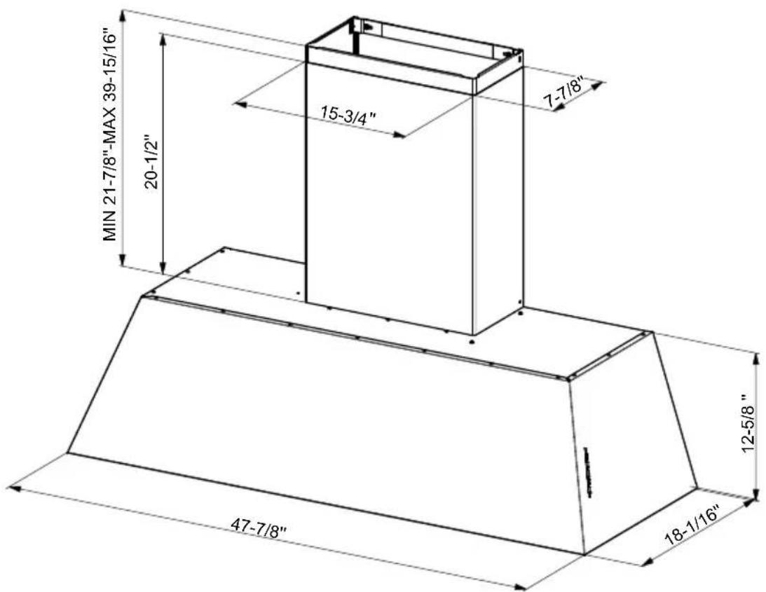
RANGEHOOD DIMENSIONS

| KMC30X |
| KMC30BI |
| KMC30NE |
| KMC36X |
| KMC36BI |
| KMC36NE |

| KMC48X |
| KMC48BI |
| KMC48NE |
MAIN PARTS
KMC30X - KMC30BI - KMC30NE
Ref. Qty. Product Components
1 1 Hood Body, complete with: Controls, Light, Filters, Blower.
2 1 Telescopic Chimney comprising:
2.1 1 Upper Section
2.2 1 Lower Section
3 1 Angle bracket
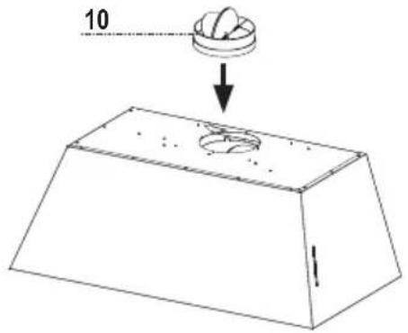
10 1 Damper ø 5 7/8"
10e 1 Support connection for recirculating
9 1 Connection for recirculating comprising:
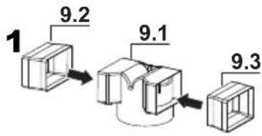
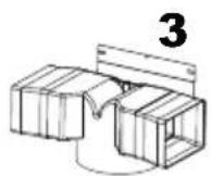
9.1 1 Connection for recirculating
9.2 1 Spacer connection for recirculating
9.3 1 Spacer connection for recirculating
8 1 Recirculation Vent Grill
Ref. Qty. Installation Components
7.2.1 2 Upper Chimney Section Fixing Brackets
12a 8 Screws 3/16" x 1 15/16"
12b 4 Screws 1/8" x 3/8"
12d 6 Screws 1/8" x 1/4"
12e 2 Screws 1/8" x 3/8"
12f 2 Screws 1/8" x 1/2"
Qty. Documentation
1 Instruction Manual
MAIN PARTS
KMC36X - KMC36BI - KMC36NE

Ref. Qty. Product Components
1 1 Hood Body, complete with: Controls, Light, Filters, Blower.
2 1 Telescopic Chimney comprising:
2.1 1 Upper Section
2.2 1 Lower Section
3 1 Angle bracket
10 1 Damper ø 5 7/8"
10e 1 Support connection for recirculating
9 1 Connection for recirculating comprising:
9.1 1 Connection for recirculating
9.2 1 Spacer connection for recirculating
9.3 1 Spacer connection for recirculating
8 1 Recirculation Vent Grill
Ref. Qty. Installation Components
7.2.1 2 Upper Chimney Section Fixing Brackets
12a 10 Screws 3/16" x 1 15/16"
12b 4 Screws 1/8" x 3/8"
12d 6 Screws 1/8" x 1/4"
12e 2 Screws 1/8" x 3/8"
12f 2 Screws 1/8" x 1/2"
Qty. Documentation
1 Instruction Manual
MAIN PARTS
KMC48X - KMC48BI - KMC48NE
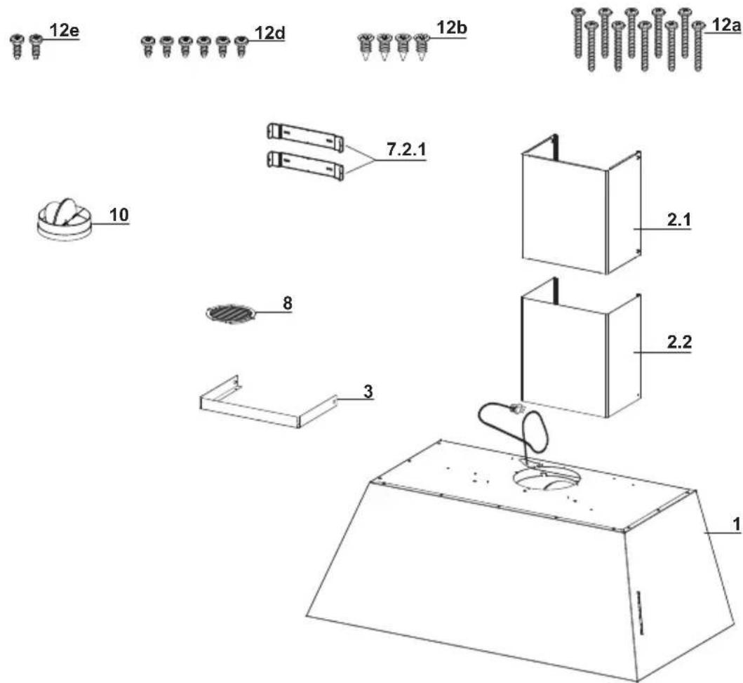
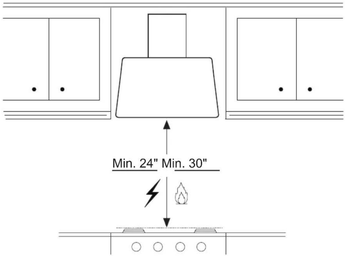
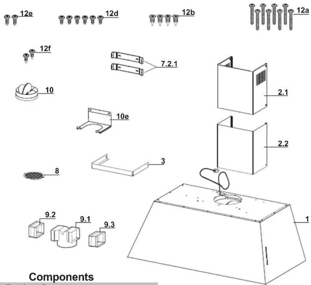
Components
Ref. Qty. Product Components
1 1 Hood Body, complete with: Controls, Light, Filters, Blower.
2 1 Telescopic Chimney comprising:
2.1 1 Upper Section
2.2 1 Lower Section
3 1 Angle bracket.
10 1 Damper ø 5 7/8"
8 1 Recirculation Vent Grill
Ref. Qty. Installation Components
7.2.1 2 Upper Chimney Section Fixing Brackets
12a 10 Screws 3/16" x 1 15/16"
12b 4 Screws 1/8" x 3/8"
12d 6 Screws 1/8" x 1/4"
12e 2 Screws 1/8" x 3/8"
Qty. Documentation
1 Instruction Manual
Choose your ducting method
INSTALLATION WITH THE CHIMNEY

Non Ducted - Recirculation Option

Choose your ducting method INSTALLATION WITHOUT THE CHIMNEY
Non Ducted - Recirculation Option
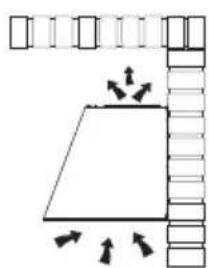
natural_image
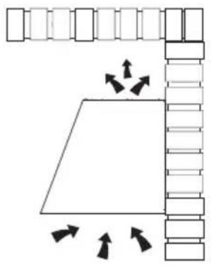
Simple line drawing of a trapezoidal shape with directional arrows, no text or symbols presentRequires purchase of Activated Charcoal Accessory When used in recirculation mode, To Reduce the Risk of Fire and Shock use only conversion Charcoal Accessory.

natural_image
Simple line drawing of a hand holding a document with a diagonal line and the number 22 below (no text or symbols on the diagram itself)Ducted Venting Options Installation

natural_image
Simple line drawing of a hand holding a sheet of paper with a diagonal line, no text or symbols present.Only for Ducted Venting Installation
Install Damper that is included with the Hood before connecting to the ductwork.
Installation Instructions
1

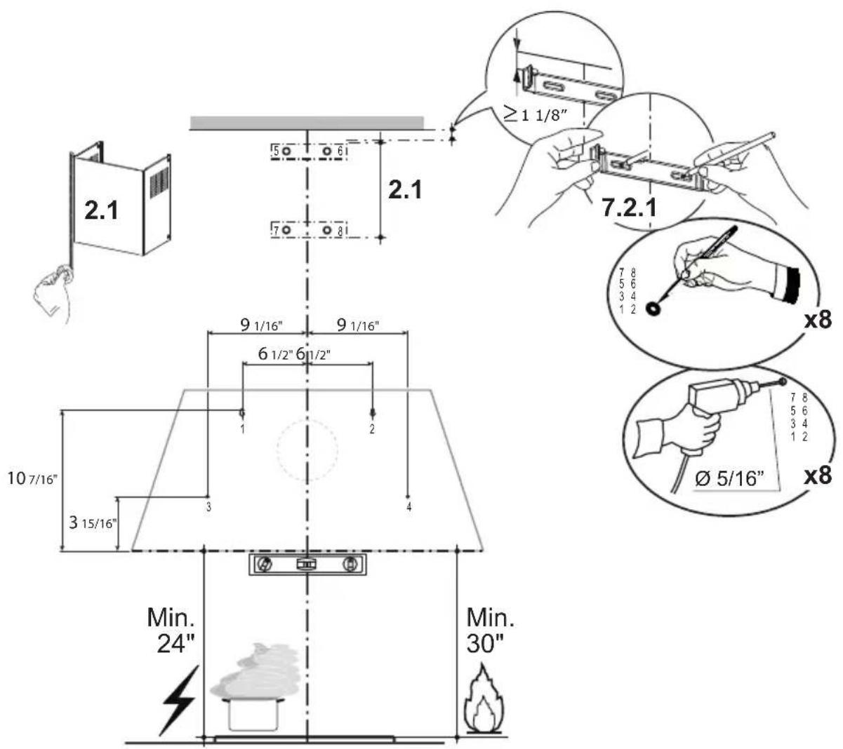
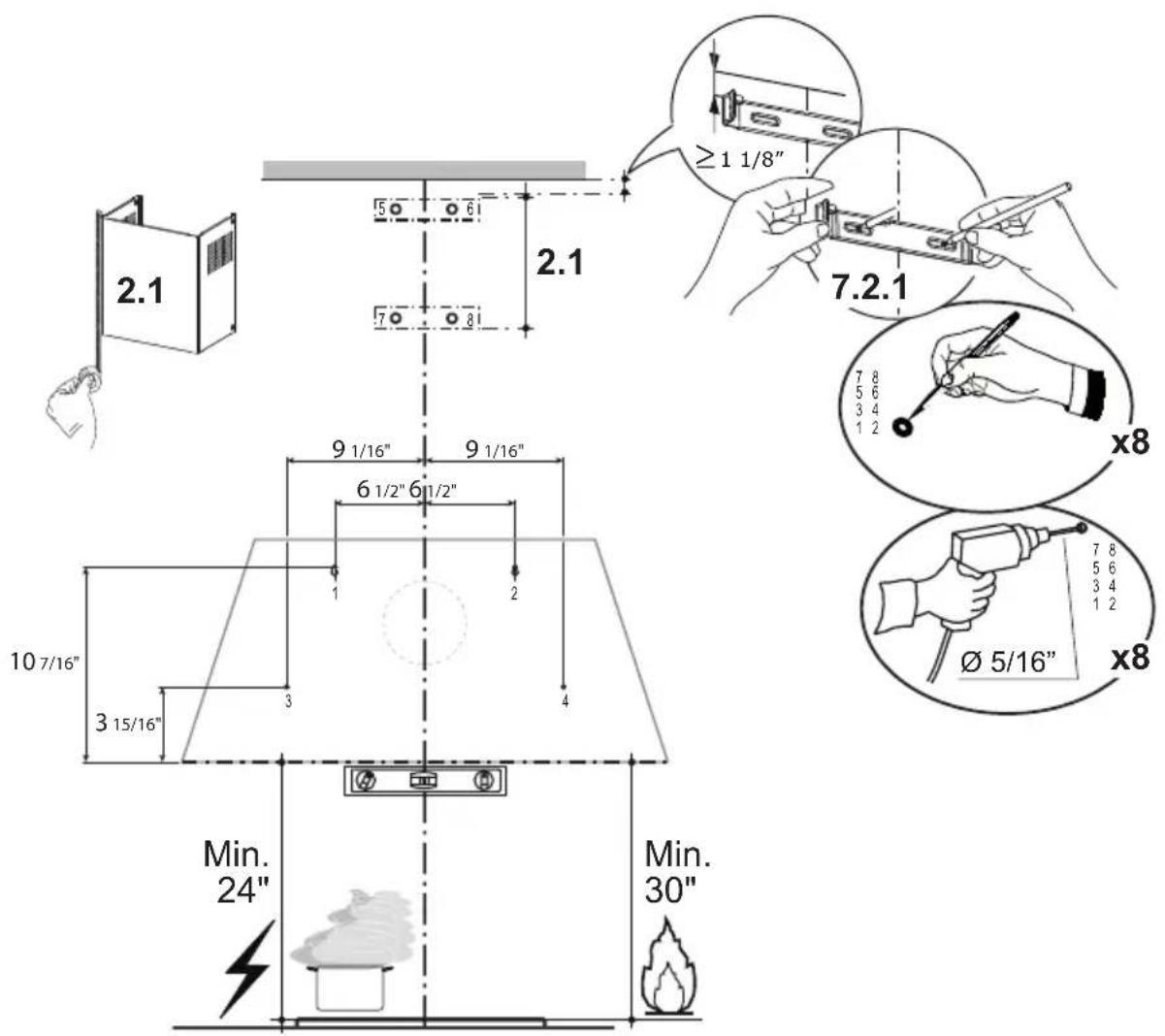
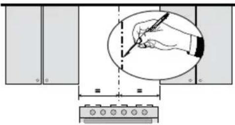
Draw a vertical line on the supporting wall as high as practical, at the center of the area in which the hood will be installed. Draw a horizontal line at where the bottom edge of the hood will be located as indicated in the figure that is a minimum of 24" above Electric cooking surface and 30" above Gas.
2.a
| KMC30X |
| KMC30BI |
| KMC30NE |
Mark the wall where indicated, 10 7/16" above the horizontal line and at 6 1/2" distance on the left and right of vertical line. Checking that the two marks are level.
Insert two wall plugs and two screws into the holes as shown not completely (purchased separately). Mark the wall where indicated, 3 15/16" above the horizontal line and at 9 1/16" distance on the left and right of vertical line. Checking that the two marks are level.
Insert two wall plugs (purchased separately).
Place a bracket 7.2.1 on the wall as shown about 1 1/8" from the ceiling or upper limit, aligning the center (notch) with the vertical reference line and mark the wall at the centers of the holes in the bracket.
Place the second bracket 7.2.1 on the wall as shown, below the first bracket, at the height of the upper chimney section supplied and aligning the center (notch) with the vertical line.
Mark the wall at the centers of the holes in the bracket and drill ∅ 5/16" as shown.
Installation screws provided for the Brackets, must be secured with wall plugs (purchased separately).
2.b
| KMC36X |
| KMC36BI |
| KMC36NE |
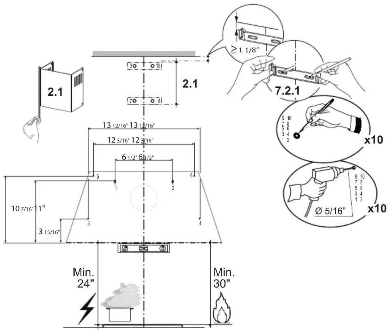
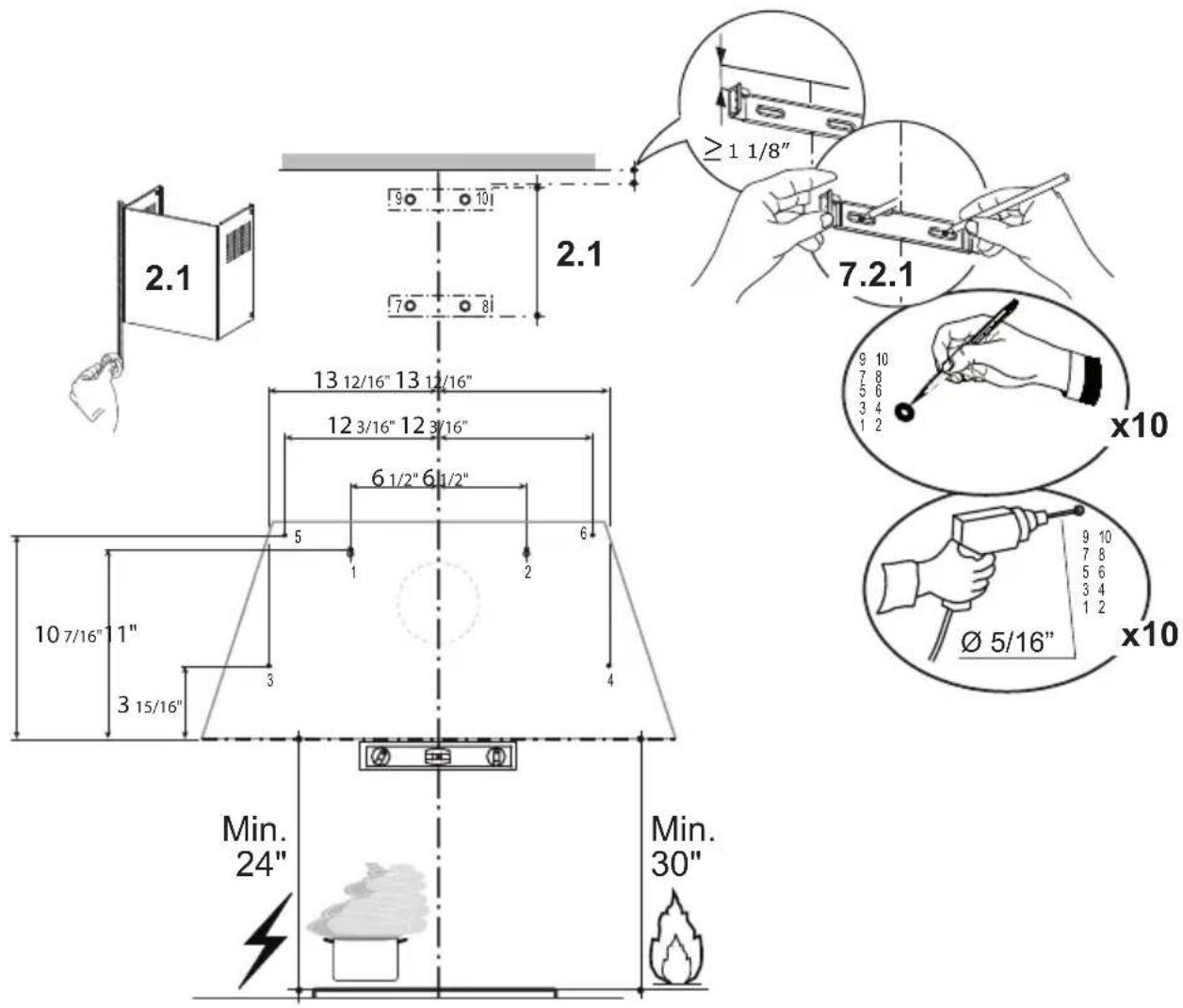
Mark the wall where indicated, 10 7/16" above the horizontal line and at 6 1/2" distance on the left and right of vertical line. Checking that the two marks are level.
Insert two wall plugs and two screws into the holes as shown not completely (purchased separately). Mark the wall where indicated, 3 15/16" above the horizontal line and at 13 12/16" distance on the left and right of vertical line. Checking that the two marks are level. Insert two wall plugs (purchased separately). Mark the wall where indicated, 11" above the horizontal line and at 12 3/16" distance on the left and right of vertical line. Checking that the two marks are level. Insert two wall plugs (purchased separately). Place a bracket 7.2.1 on the wall as shown about 1 1/8" from the ceiling or upper limit, aligning the center (notch) with the vertical reference line and mark the wall at the centers of the holes in the bracket.
Place the second bracket 7.2.1 on the wall as shown, below the first bracket, at the height of the upper chimney section supplied and aligning the center (notch) with the vertical line.
Mark the wall at the centers of the holes in the bracket and drill 5/16" as shown. Installation screws provided for the Brackets, must be secured with wall plugs (purchased separately).
2.c
| KMC48X |
| KMC48BI |
| KMC48NE |

Mark the wall where indicated, 10 7/16" above the horizontal line and at 6 1/2" distance on the left and right of vertical line. Checking that the two marks are level.
Insert two wall plugs and two screws into the holes as shown not completely (purchased separately). Mark the wall where indicated, 3 15/16" above the horizontal line and at 18 14/16" distance on the left and right of vertical line. Checking that the two marks are level. Insert two wall plugs (purchased separately).
Mark the wall where indicated, 11 6/16" above the horizontal line and at 11 11/16" distance on the left and right of vertical line. Checking that the two marks are level. Insert two wall plugs (purchased separately).
Place a bracket 7.2.1 on the wall as shown about 1 1/8" from the ceiling or upper limit, aligning the center (notch) with the vertical reference line and mark the wall at the centers of the holes in the bracket.
Place the second bracket 7.2.1 on the wall as shown, below the first bracket, at the height of the upper chimney section supplied and aligning the center (notch) with the vertical line.
Mark the wall at the centers of the holes in the bracket and drill ø 5/16" as shown.
Installation screws provided for the Brackets, must be secured with wall plugs (purchased separately).
INSTALLATION WITH THE CHIMNEY

natural_image
Simple line drawing of a 3D rectangular box with a small protrusion on top (no text or symbols)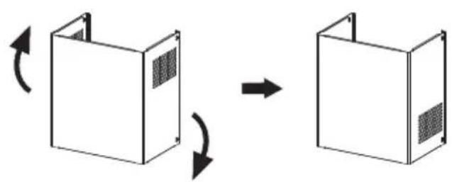
natural_image
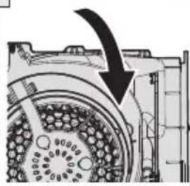
Diagram showing two 3D rectangular units with internal patterns, connected by an arrow indicating rotation or transformation (no text or symbols)3
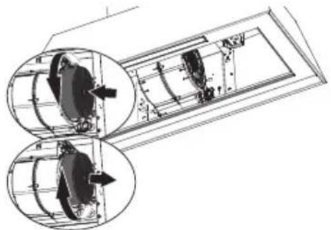
Remove the filters one at a time, supporting them with one hand and turning the safety knobs (pull and turn).
Do not discard the filters and set aside for future use.

natural_image
Architectural detail showing a window with grating and a magnified inset of hands holding a small object (no text or symbols)4
Hook and fix the hood body onto the wall.
5

natural_image
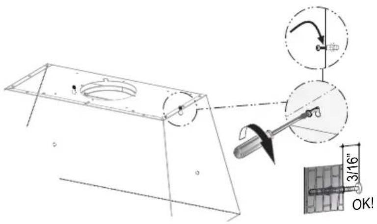
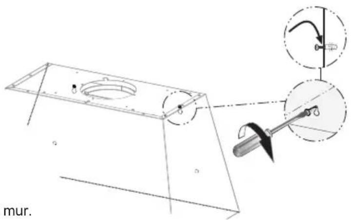
Technical diagram of a mechanical assembly with labeled components and an inset showing a tool (no text or symbols present)From inside fully secure the screws 12a.
6
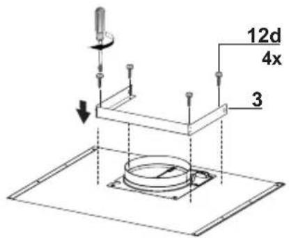
Use the four screws to secure the angle bracket.
7
Vertical or Horizontal
Ducting Installation
natural_image
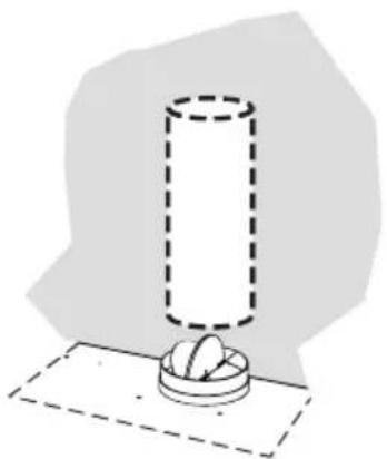
Simple line drawing of a cylindrical object with a base, placed on a flat surface (no text or symbols)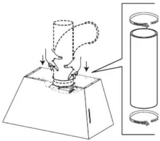
natural_image
Diagram showing a mechanical press or clamping mechanism with a cylindrical component and a base, no text or symbols present.Install Roof or Wall Cap purchased separately. Connect the 6" metal ductwork to the Roof or Wall Cap and then attach ductwork.
Install the 2 fixing brackets 7.2.1 to the middle and upper holes and secure with screws 12a as shown.
8

9

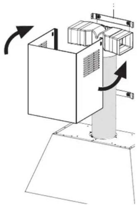
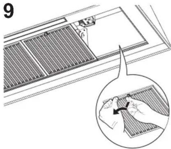
Slightly widen the two sides of the upper chimney and hook them behind the brackets 7.2.1, making sure that they are well seated.
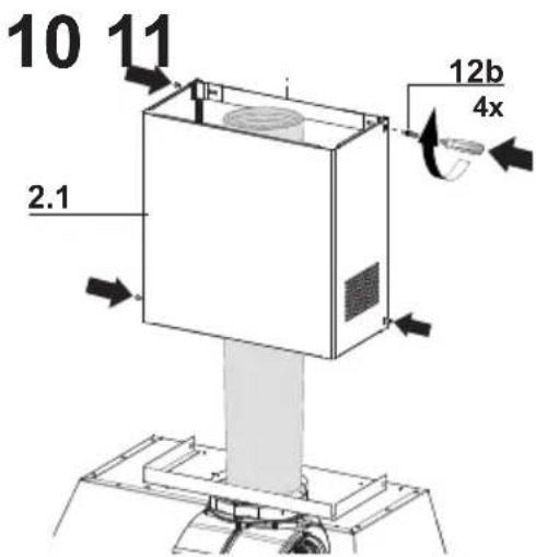
Secure the sides to the brackets by using the 4 screws 12b.

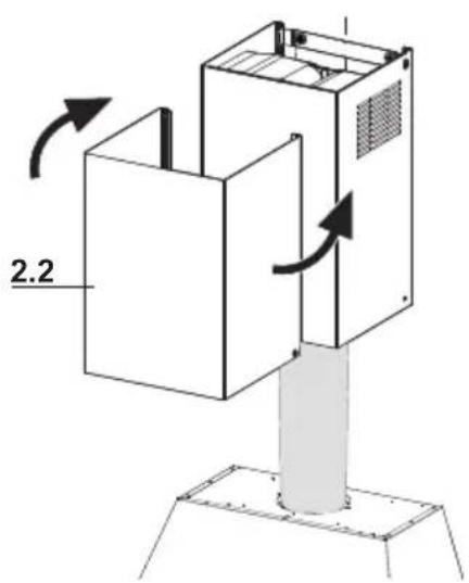
Slightly widen the two sides of the the lower chimney hood and hook them between the upper section and the wall, making sure that they are properly housed.
12

Fix the the lower chimney hood laterally to the hood body using the 2 screws 12e supplied.
13 14 No-Ducted Recirculation Option
natural_image
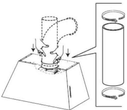
Diagram showing a mechanical press or clamping operation with a cylinder and coiled cable, no text or symbols present.Only for the recirculation version, connect the hood to the Air outlet.
natural_image
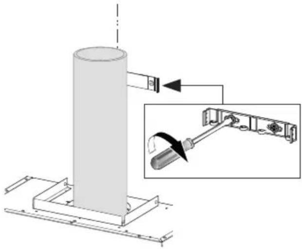
Technical diagram showing a cylindrical component mounted on a base with an inset close-up of its internal structure (no text or symbols present)Fix the lower Bracket 7.2.1 with two screws 12a supplied as shown.
15

Fix the Ductless Diverter with two screws 12f supplied as shown.
16

natural_image
Technical diagram of a mechanical assembly with a tool and connector, showing internal components without any text or symbols.
natural_image
Technical line drawing of a cylindrical mechanical component mounted on a metal frame (no text or symbols)Fix the Ductless Diverter with two screws 12a supplied as shown.
17
natural_image
Diagram of a mechanical device with rotating components and directional arrows indicating motion (no text or symbols)Slightly widen the two sides of the upper chimney and hook them behind the brackets and connect to the Ductless Diverter, making sure that they are well seated.
18

Secure the sides to the brackets by using the 4 screws 12b.
19
Slightly widen the two sides of the lower chimney hood and hook them between the upper section and the wall, making sure that they are properly housed.
20

Fix the the lower chimney hood laterally to the hood body using the 2 screws 12e supplied.
21
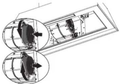
Attach each charcoal filter to the black grid on each side of the blower. Press the charcoal filter tightly to the black grid on the blower side and rotate the filter clockwise (towards the front of the hood) until it locks into place.
Turn counterclockwise (towards the back of the hood) to remove.
natural_image
Technical line drawing of a mechanical assembly with two circular insets showing internal components (no text or symbols)22

natural_image
Diagram showing a hand holding a grid device with an arrow indicating rotation (no text or symbols present)Replace the filters one at a time, supporting them with one hand and turning the safety knobs (pull and turn). Do not discard the filters and set aside for future use.
INSTALLATION WITHOUT THE CHIMNEY
Non Ducted - Recirculation Option
natural_image
Diagram showing a trapezoidal shape with directional arrows indicating flow or movement, surrounded by stacked rectangular blocks (no text or symbols)1

Draw a vertical line on the supporting wall as high as practical, at the center of the area in which the hood will be installed. Draw a horizontal line at where the bottom edge of the hood will be located as indicated in the figure that is a minimum of 24" above Electric cooking surface and 30" above Gas.
2.a

KMC30X
KMC30BI
KMC30NE
Draw a horizontal line where indicated above the cooking surface.
Mark the wall at the centers of the holes in the bracket and mark the point 1 and 2 for the Hood Body installation as shown.
Drill ∅ 5/16" holes at all the center points marked (point 1,2,3,4) as shown.
2.b

| KMC36X |
| KMC36BI |
| KMC36NE |
Draw a horizontal line where indicated above the cooking surface.
Mark the wall at the centers of the holes in the bracket and mark the point 1 and 2 for the Hood Body installation as shown.
Drill ∅ 5/16" holes at all the center points marked (point 1,2,3,4,5,6) as shown.
2.c

| KMC48X |
| KMC48BI |
| KMC48NE |
Draw a horizontal line where indicated above the cooking surface.
Mark the wall at the centers of the holes in the bracket and mark the point 1 and 2 for the Hood Body installation as shown.
Drill ∅ 5/16" holes at all the center points marked (point 1,2,3,4,5,6) as shown.
3
Remove the filters one at a time, supporting them with one hand and turning the safety knobs (pull and turn).
Do not discard the filters and set aside for future use.
natural_image
Technical line drawing of a ventilation grille with an inset showing hand positioning (no text or symbols)4
Hook and fix the hood body onto the wall.
natural_image
Technical diagram showing a mechanical assembly with a bracket and tool, no visible text or symbols5
From inside fully secure the screws 12a.
natural_image
Technical diagram of a mechanical assembly with a tool and component, showing no readable text or symbols.6
Fix the Recirculation Vent Grill with two screws.
7
Attach each charcoal filter to the black grid on each side of the blower. Press the charcoal filter tightly to the black grid on the blower side and rotate the filter clockwise (towards the front of the hood) until it locks into place.
Turn counterclockwise (towards the back of the hood) to remove.
natural_image
Technical line drawing of a mechanical assembly with two circular insets showing internal components (no text or symbols)8
natural_image
Diagram showing a window with grating and a magnified inset of hands adjusting a grid (no text or symbols)Replace the filters one at a time, supporting them with one hand and turning the safety knobs (pull and turn). Do not discard the filters and set aside for future use.
INSTALLATION WITHOUT THE CHIMNEY
Ducted Venting Options Installation

natural_image
Diagram showing a structural beam with distributed loads and directional arrows, no text or symbols present1

| KMC30X |
| KMC30BI |
| KMC30NE |
| KMC36X |
| KMC36BI |
| KMC36NE |
| KMC48X |
| KMC48BI |
| KMC48NE |
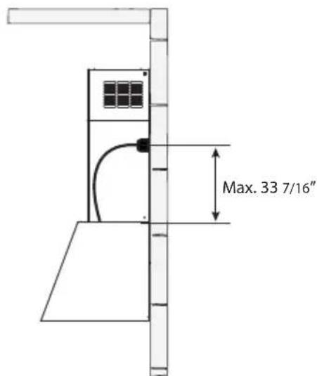
Use this dimensional drawing to help with planning of duct connection.
2
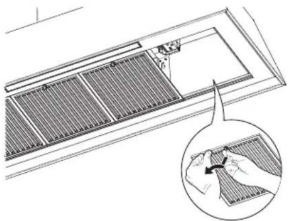
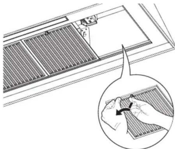
Remove the filters one at a time, supporting them with one hand and turning the safety knobs (pull and turn).
Do not discard the filters and set aside for future use.

natural_image
Technical illustration of a solar panel installation with a magnified inset showing hand positioning (no text or symbols)3

natural_image
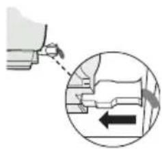
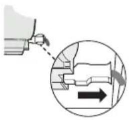
Diagram showing a hand operating a tool with an arrow indicating direction, no text or symbols presentFrom inside the hood, use the flat head screwdriver as shown in image above, to disconnect the right Connectors from the blower.
4

natural_image
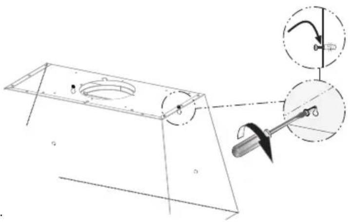
Technical diagram showing a mechanical assembly with a hexagonal component and circular features, no text or symbols present.Unscrew the 4 screws that hold the plate and unlock it from the initial position as shown in image.
5
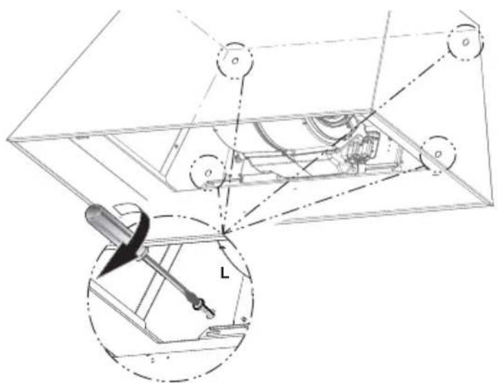
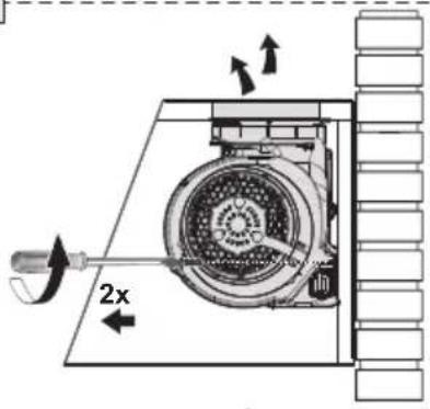
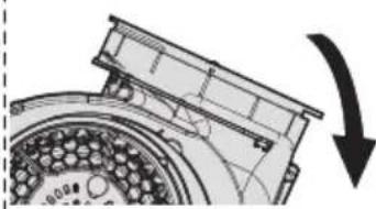
Warning! Don't stress the power cable during the blower rotation operation and carry out the operation in at least two people.
Unscrew the 2 screws that hold the blower and unlock it from the initial position as shown in Image a.
After removing blower rotate as shown until it is in the correct rear venting position as shown in Image b-c.
Use the two screws that were removed to secure the blower as shown in Image d.
a
d

b
natural_image
Technical diagram of a mechanical component with a curved arrow indicating rotation or assembly (no text or symbols present)C
natural_image
Technical diagram of a mechanical assembly with a curved arrow indicating motion or direction (no text or symbols present)6
Install to the Roof or Wall attach ductwork.

natural_image
Technical line drawing of a mechanical device with hands operating it, showing internal components and alignment arrows (no text or symbols)7

natural_image
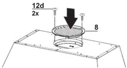
Pure technical diagram showing a mechanical component with an arrow indicating downward force (no text or symbols)Use the four screws that were removed to secure the plate as shown in image.
8
natural_image
Diagram showing a mechanical component being inserted into a housing, with an inset magnified view highlighting the internal structure (no text or symbols present)From inside the hood re-connect the Connectors on the right side shown in the image above.
Replace the filters one at a time, supporting them with one hand and turning the safety knobs (pull and turn). Do not discard the filters and set aside for future use.
ELECTRICAL INSTALLATION WITH CONNECTION CABLE
GROUNDING INSTRUCTIONS This appliance must be grounded. In the event of an electrical short circuit, grounding reduces the risk of electric shock by providing an escape wire for the electric current. This appliance is equipped with a cord having a grounding wire with a grounding plug. The plug must be plugged into an outlet that is properly installed and grounded. WARNING - Improper grounding can result in a risk of electric shock.
Consult a qualified electrician if the grounding instructions are not completely understood, or if doubt exists as to whether the appliance is properly grounded.
Do not use an extension cord. If the power supply cord is too short, have a qualified electrician install an outlet near the appliance.
USE AND CARE INFORMATION
For Best Results
Start the rangehood several minutes before cooking to develop proper airflow. Allow the rangehood to operate for several minutes after cooking is complete to clear all smoke and odors from the kitchen.
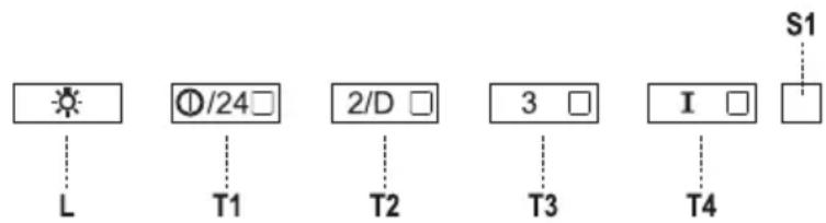
| Button | Led Function | |
| L - Turns the lights ON/OFF at maximum strength. | ||
| T1 Fixed Turns the motor on/off at speed one. | ||
| T2 Fixed Turns the Motor on at speed two. | ||
| T3 Fixed Turns the Motor on at speed three. | ||
| T4 Flashing Turns the Motor on at Intensive.Speed. This speed is timed to run for 6 minutes. At the end of this time, the system returns automatically to the speed that was set before. If it is activated with the motor turned off, the hood will switch to OFF at the end of the time. | ||
| S1 | Fixed | Signals the Metal Grease Filter saturation alarm, indicating that it is necessary to wash the filters. The alarm is triggered after the Hood has been in operation for 100 working hour |
| Flashing | When this is activated, it signals the Activated Charcoal Filter saturation alarm, indicating that the filter must be changed; the Metal Grease Filters must also be washed. The Activated Charcoal Filter saturation alarm comes into operation after the Hood has been working for 200 hours. | |
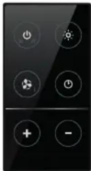
REMOTE CONTROL (OPTIONAL)
The remote control is powered by a CR2032 type 3 V battery (not included).
- Do not place the remote control near heat sources.
- Do not discard the batteries with normal waste, they must be put into the specific containers.
natural_image
Black remote control panel with eight function icons (power, sun, refresh, gear, clock, plus, minus) arranged in a grid (no text or labels)| ↓ | Turns the motor On and Off. | |
| ↓↑ | - | |
| % | - | |
| Turns the lights On/Off. | ||
| Press and hold for 2sec to turn the Hood lights On/Off at reduced intensity. | ||
| ↔ | Activates/Deactivates Intensive operation. | |
| ◎ | Brief pressure: Activates/Deactivates the Delay function: automatic switch-off with a 30' delay. The display shows the operating speed and the dot at the bottom right flashes once a second.Press for 2 seconds: Activates/Deactivates the 24h function: turns the suction motor on at speed one and effects one 10 minute extraction every hour. The display shows the number 24 and the dot at the bottom right flashes once a second. | |
| + | Increases the working speed of the motor. | |
| - | Decreases the working speed of the motor. | |
Cleaning metal grease filters
These can be washed in the dishwasher, and need to be cleaned whenever the S1 Led comes on or at least once every 2 months use, or more frequently if use is particularly intensive.
Resetting the alarm signal
• Turn the Lights and the Suction Motor off.
- Press T3 and hold for at least 3 seconds, until LED flashes three times in confirmation.
Cleaning
- Remove the filter, pushing the lever towards the back of the unit and at the same time pulling downward.
- Wash the filter without bending it, leave it to dry thoroughly before replacing (if the surface of the filter changes color over time, this will have absolutely no effect on its efficiency).
- Replace, taking care to ensure that the handle faces forward.
- No water can be present in filters before installing back in hood.

natural_image
Technical line drawing of a ventilation duct with a magnified inset showing hand positioning (no text or symbols)Replacing Activated Charcoal Filter
This cannot be washed or regenerated, and must be changed when led S1 starts to flash, or at least once every 4 months. The Alarm signal, if it has been activated, only appears when the Suction motor is turned on.
Resetting the alarm signal
- Turn the Lights and the Suction Motor off.
- Press T3 and hold for at least 3 seconds, until LED flashes three times in confirmation.
Cleaning
- Remove the charcoal filter by rotating it clockwise (backwards) until it unlocks from the motor housing and pull off sideways.
- To re-insert each charcoal filter, place up against the side of the blower and push it inward. Then turn the charcoal filter clockwise (forward) until it fits into place.
- CAUTION: When used in recirculation mode, to Reduce the Risk of Fire and Shock use only conversion Charcoal Accessory.

natural_image
Technical diagram showing two views of a mechanical device with internal components and directional arrows (no text or symbols)LED LIGHTING UNIT
• LED lights must be replaced by Bertazzoni factory authorized service.
Wiring Diagram

Please kindly register on our web site www.bertazzoni.com to validate your new product warranty and help us to assist you better in case of any inconvenience.
TWO YEAR LIMITED WARRANTY
The warranties provided by Bertazzoni Spain in this statement apply exclusively to Bertazzoni appliances and accessories sold as new products to the original owner by a Bertazzoni authorized distributor, retailer, dealer or service center and installed in the United States and Canada. The warranties provided in this statement are not transferable and have validity from the date of installation.
COVERAGE INFORMATION
Bertazzoni SpA will repair or replace any component part which fails or proves defective due to materials and/or workmanship within 2 years from the date of installation and under conditions of normal residential use. Repair or replacement will be free of charge, including labor at standard rates and shipping expenses. Repair service must be performed by a Bertazzoni Authorized Service Center during normal working hours.
COSMETIC WARRANTY
Bertazzoni will cover parts showing cosmetic defects in material and workmanship for a period of thirty (30) days from date of installation of the unit. This coverage will include scratches, stains, surface imperfections on stainless steel, paint and porcelain, with the exclusion of slight differences in color due to materials and painting/enamelling technologies.
Exclusions are labor costs, B stock items, out - of - box appliances and display units.
HOW TO OBTAIN SERVICE
To obtain service please contact Bertazzoni Customer Service at the numbers below and make sure to have model number, serial number, and date of purchase ready. This information will be requested by our team and is crucial to speeding up resolution.
UNITED STATES
https://us.bertazzoni.com/more/support
Phone: 866-905-0010
CANADA
https://ca.bertazzoni.com/more/support
Save proof of original purchase or of original installation to establish warranty period. Copy of the product serial tag is affixed to the back cover of the instruction manual.
WHAT IS NOT COVERED
- The product used in any commercial/business application.
- Repair service provided by other than a Bertazzoni authorized service agent.
- Damage or repair service to correct service provided by an unauthorized agency or the use of unauthorized parts.
- Installation not in accordance with local electrical codes or plumbing codes.
- Defects or damage due to improper storage of the product.
- Defects or damage or missing parts on products sold out of the original factory packaging or from displays.
- Service calls or repairs to correct the installation of the product and/or related accessories. 8. Service calls to connect, convert or otherwise repair the electrical wiring / gas line / water line to properly use the product.
- Service calls to provide instructions on the use of a Bertazzoni product.
- Repair service due to product usage in manner other than what is normal and customary for home use.
- Replacement of wear and tear parts.
- Replacement of glasses and lightbulbs if they are claimed to have failed later than 30 days after installation and in no case later than 4 months after date of purchase.
- Defects and damages arising from accident, alteration, misuse, abuse, improper installation.
- Defects and damages arising from transportation of the product to the home of the owner.
- Defects and damage arising from external forces beyond the control of Bertazzoni SpA such as fire, flood, earthquakes and other acts of God.
In case the product will be installed in a remote area, where certified trained technicians are not reasonably available, the customer will be responsible for the transportation costs for the delivery of the product to the nearest authorized service center or for the displacement costs of a certified trained technician.
Bertazzoni does not assume any responsibility for incidental or consequential damages. Some states do not allow the exclusion or limitation of incidental or consequential damages, so the above limitation or exclusion may not apply to you. This warranty gives you specific legal rights and you may also have other rights which may vary from state to state or province to province.
VEUILLEZ LIRE ET CONSERVER LA PRÉSENTE NOTICE AVANT DE COMMENCER L'INSTALLATION DE LA HOTTE DE CUISINE
AVERTISSEMENT : POUR RÉDUIRE LE RISQUE D'UN FEU DE GRAISSE SUR LA TABLE DE CUISSON :
| KMC30X |
| KMC30BI |
| KMC30NE |
| KMC36X |
| KMC36BI |
| KMC36NE |
| KMC48X |
| KMC48BI |
| KMC48NE |

PIÈCES PRINCIPALES
KMC30X - KMC30BI - KMC30NE

Composants
KMC36X - KMC36BI - KMC36NE

Composants
KMC48X - KMC48BI - KMC48NE

Composants
12a 10 Vis 3/16" x 1 15/16"
12b 4 Vis 1/8" x 3/8"
12d 6 Vis 1/8" x 1/4"
12e 2 Vis 1/8" x 3/8"
Qté. Documentation
1 Mode d'emploi
natural_image
Simple line drawing of a hand holding a document with a diagonal line and the number 44 (no text or symbols beyond the number)natural_image
Diagram of a mechanical or electrical component with directional arrows and a circular component, mounted on a brick wall (no text or symbols)
natural_image
Simple line drawing of a hand holding a document with a diagonal line and the number 51 (no text or symbols beyond the number)natural_image
Diagram showing a tilted rectangular object with directional arrows indicating movement, surrounded by stacked rectangular blocks (no text or symbols)| KMC30X |
| KMC30BI |
| KMC30NE |
| KMC36X |
| KMC36BI |
| KMC36NE |
| KMC48X |
| KMC48BI |
| KMC48NE |

natural_image
Simple line drawing of a 3D rectangular box with a small protrusion on top (no text or symbols)
natural_image
Diagram showing two 3D rectangular units with internal patterns, connected by an arrow indicating rotation or transformation (no text or symbols)3
natural_image
Architectural detail showing a window with grating and a magnified inset of hands holding a small object (no text or symbols)4
5

natural_image
Technical diagram of a mechanical assembly with labeled components and an inset showing a tool (no text or symbols present)natural_image
Simple line drawing of a cylindrical object mounted on a base, with no text or symbols present.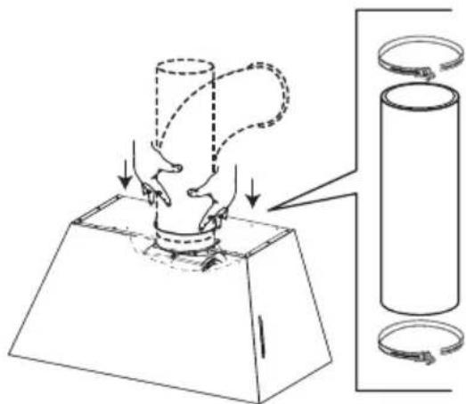
natural_image
Diagram of a mechanical press or clamping device with a cylindrical component and a base, showing force application and motion arrows (no text or symbols)natural_image
Diagram showing a mechanical press or clamping mechanism with a cylinder and coiled cable, no text or symbols present.natural_image
Technical diagram of a cylindrical mechanical assembly with an inset showing a tool interacting with a bracket (no text or symbols present)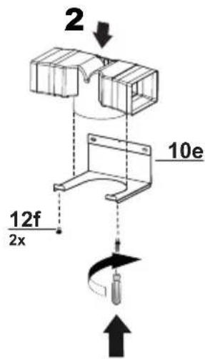
natural_image
Technical diagram of a mechanical assembly with a tool and connector, showing internal components without any text or symbols.
natural_image
Technical line drawing of a cylindrical mechanical component mounted on a metal frame (no text or symbols)natural_image
Diagram of a mechanical device with rotating components and directional arrows indicating motion (no text or symbols)natural_image
Technical line drawing of a mechanical assembly with two circular insets showing internal components (no text or symbols)22

natural_image
Diagram showing a hand holding a tool inside a grid-like structure, with an inset magnifying the action (no text or symbols present)natural_image
Diagram showing a trapezoidal shape with directional arrows indicating flow or movement, surrounded by stacked rectangular blocks (no text or symbols)1
| KMC36X |
| KMC36BI |
| KMC36NE |
| KMC48X |
| KMC48BI |
| KMC48NE |
natural_image
Technical line drawing of a ventilation grille with an inset showing hand positioning (no text or symbols)4
natural_image
Technical diagram of a mechanical assembly with a magnified inset showing a tool and component (no text or symbols)natural_image
Technical line drawing of a mechanical assembly with two circular insets showing internal components (no text or symbols)8

natural_image
Diagram showing a window with grating and a magnified inset of hands adjusting a grid (no text or symbols)natural_image
Diagram showing a structural beam with distributed loads and directional arrows, no text or symbols present1

| KMC30X |
| KMC30BI |
| KMC30NE |
| KMC36X |
| KMC36BI |
| KMC36NE |
| KMC48X |
| KMC48BI |
| KMC48NE |
natural_image
Technical line drawing of a solar panel installation with a magnified inset showing hand positioning (no text or symbols)3
natural_image
Diagram showing a hand operating a tool with an arrow indicating direction, no text or symbols presentnatural_image
Technical diagram showing a mechanical assembly with a hexagonal component and circular features, no text or symbols present.b

natural_image
Technical diagram of a mechanical component with circular features and a downward arrow indicating rotation (no text or symbols)C

natural_image
Technical diagram of a mechanical assembly with a curved arrow indicating motion or direction (no text or symbols present)6
natural_image
Technical line drawing of a mechanical device with hands operating it, showing internal components and alignment arrows (no text or symbols)7

natural_image
Pure technical diagram showing a mechanical component with an arrow indicating downward force (no text or symbols)natural_image
Diagram showing a mechanical component being inserted into a housing, with an inset magnified view highlighting a specific section (no text or symbols present)TÉLÉCOMMANDE (EN OPTION)
natural_image
Close-up of a black remote control panel with eight function buttons (power, sun, refresh, alarm, clock, plus, minus) arranged in a grid (no text or symbols beyond basic icons)natural_image
Technical line drawing of a kitchen air conditioner unit with a magnified inset showing hand cleaning the grille (no text or symbols)natural_image
Technical diagram of a mechanical device with two circular insets showing internal components (no text or symbols)https://us.bertazzoni.com/more/support
Phone: 866-905-0010
CANADA
https://ca.bertazzoni.com/more/support


- READ AND SAVE THESE INSTRUCTIONS BEFORE YOU START INSTALLING THIS RANGEHOOD
- VENTING REQUIREMENTS
- Cold Weather installations
- WARNING
- ELECTRICAL REQUIREMENTS
- State of California Proposition 65 Warning (US only)
- MAIN PARTS
- KMC30X - KMC30BI - KMC30NE
- Ref. Qty. Product Components
- Ref. Qty. Installation Components
- Qty. Documentation
- KMC36X - KMC36BI - KMC36NE
- KMC48X - KMC48BI - KMC48NE
- Components
- Choose your ducting method INSTALLATION WITHOUT THE CHIMNEY
- Only for Ducted Venting Installation
- Installation Instructions
- 2.a
- 2.b
- 2.c
- INSTALLATION WITH THE CHIMNEY
- 3
- 4
- 5
- 6
- 21
- 22
- INSTALLATION WITHOUT THE CHIMNEY
- Non Ducted - Recirculation Option
- 7
- 8
- Ducted Venting Options Installation
- 2
- ELECTRICAL INSTALLATION WITH CONNECTION CABLE
- USE AND CARE INFORMATION
- For Best Results
- REMOTE CONTROL (OPTIONAL)
- Cleaning metal grease filters
- Resetting the alarm signal
- Cleaning
- Replacing Activated Charcoal Filter
- LED LIGHTING UNIT
- TWO YEAR LIMITED WARRANTY
- COVERAGE INFORMATION
- COSMETIC WARRANTY
- HOW TO OBTAIN SERVICE
- WHAT IS NOT COVERED
- VEUILLEZ LIRE ET CONSERVER LA PRÉSENTE NOTICE AVANT DE COMMENCER L'INSTALLATION DE LA HOTTE DE CUISINE
- PIÈCES PRINCIPALES
- Composants
- Qté. Documentation
- TÉLÉCOMMANDE (EN OPTION)
Brand : BERTAZZONI
Model : KMC48BI
Category : Range hood