
3355 - Multimeter PeakTech - Free user manual and instructions
Find the device manual for free 3355 PeakTech in PDF.
User questions about 3355 PeakTech
0 question about this device. Answer the ones you know or ask your own.
Ask a new question about this device
Download the instructions for your Multimeter in PDF format for free! Find your manual 3355 - PeakTech and take your electronic device back in hand. On this page are published all the documents necessary for the use of your device. 3355 by PeakTech.
USER MANUAL 3355 PeakTech
text_image
PeakTech 3360 DMM DC: 399.99 TRUE RMS CAP: 1Hz Voltage: -C/-78 OFF TGA Cable to be seen Cable to be seen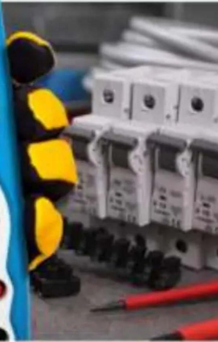
natural_image
Street scene with a yellow traffic light and a multi-story building in the background (no visible text or symbols)PeakTech® 3355 / 3360
text_image
1 399.99! 2 3 4 5 6 7 8 9 10 11 200mm 300mm 300mm 300mm 300mm 300mm 300mm 300mm 300mm 300mm 300mm 300mm 300mm 300mm 300mm 300mm 300mm 300mm 300mm 300mm 300mm SOLD TANG SOLD CHIN SOLD COOKING SOLD FLOWING SOLD WMG SOLD FLIGHTING SOLD FLAWING SOLD FLAWING SOLD FLAWING SOLD FLAWING SOLD FLAWING SOLD FLAWING SOLD FLAWING SOLD FLAWING SOLD FLAWING SOLD FLAWING SOLD FLAWING SOLD FLAWING SOLD FLAWING SOLD FLAWING SOLD FLAWING SOLD FLAWING SOLD FLAWING SOLVENTION SOLVENTION SOLVENTION SOLVENTION SOLVENTION SOLVENTION SOLVENTION SOLVENTION SOLVENTION SOLVENTION SOLVENTION SOLVENTION SOLVENTION SOLVENTION SOLVENTION SOLVENTION SOLVENTION SOLVENTION SOLVENTION SOLVENTION SOLVENTIOnatural_image
Line drawing of a handheld device with labeled ports (A, B) and connectors, no text or symbols present.
text_image
F1-F2This product complies with the requirements of the following European Community Directives: 2014/30/EC (Electromagnetic Compatibility) and 2014/35/EC (Low Voltage) as amended by 2014/32/EU (CE-Marking). Overvoltage category III 1000V; over-voltage category IV 600V; pollution degree 2.
CAT I: For signal level, telecommunication, electronic with small transient over voltage
CAT II: For local level, appliances, main wall outlets, portable equipment
CAT III: Distribution level, fixed installation, with smaller transient over-voltages than CAT IV.
CAT IV: Units and installations, which are supplied overhead lines, which are stand in a risk of persuade of a lightning, i.e. main-switches on current input, over-voltage-diverter, current use counter.
To ensure safe operation of the equipment and eliminate the danger of serious injury due to short-circuits (arcing), the following safety precautions must be observed.
Damages resulting from failure to observe these safety precautions are exempt from any legal claims whatever.
* Do not use this instrument for high-energy industrial installation measurement. This instrument is intended for use in installation over-voltage category III.
* Do not exceed the maximum permissible input ratings (danger of serious injury and/or destruction of the equipment).
* The meter is designed to withstand the stated max voltages. If it is not possible to exclude without that impulses, transients, disturbance or for other reasons, these voltages are exceeded a suitable prescale (10:1) must be used.
* Replace a defective fuse only with a fuse of the original rating. Never short-circuit fuse or fuse holding.
* Disconnect test leads or probe from the measuring circuit before switching modes or functions.
* Do not conduct voltage measurements with the test leads connected to the mA/A- and COM-terminal of the equipment.
* The 10A-range is protected. To avoid damage or injury, use the meter only in circuits limited by fuse or circuit breaker to 10A or 2000VA.
* To avoid electric shock, disconnect power to the unit under test and discharge all capacitors before taking any resistance measurements.
* Do not conduct current measurements with the leads connected to the V/Ω-terminals of the equipment.
* Check test leads and probes for faulty insulation or bare wires before connection to the equipment.
* To avoid electric shock, do not operate this product in wet or damp conditions. Conduct measuring works only in dry clothing and rubber shoes, i. e. on isolating mats.
* Never touch the tips of the test leads or probe.
* Comply with the warning labels and other info on the equipment.
* Always start with the highest measuring range when measuring unknown values.
* Do not subject the equipment to direct sunlight or extreme temperatures, humidity or dampness.
* Do not subject the equipment to shocks or strong vibrations.
* Do not operate the equipment near strong magnetic fields (motors, transformers etc.).
* Keep hot soldering irons or guns away from the equipment.
* Allow the equipment to stabilize at room temperature before taking up measurement (important for exact measurements).
* Do not input values over the maximum range of each measurement to avoid damages of the meter.
* Do not turn the rotary function switch during voltage or current measurement, otherwise the meter could be damaged.
* Use caution when working with voltages above 35 V DC or 25 V AC. These Voltages pose shock hazard.
* Replace the battery as soon as the battery indicator “BAT” appears. With a low battery, the meter might produce false reading that can lead to electric shock and personal injury.
* Fetch out the battery when the meter will not be used for long period.
* Periodically wipe the cabinet with a damp cloth and mid detergent. Do not use abrasives or solvents.
* The meter is suitable for indoor use only
* Do not operate the meter before the cabinet has been closed and screwed safely as terminal can carry voltage.
* Do not store the meter in a place of explosive, inflammable substances.
* Do not modify the equipment in any way
* Do not place the equipment face-down on any table or work bench to prevent damaging the controls at the front.
* Opening the equipment and service – and repair work must only be performed by qualified service personnel
* Measuring instruments don't belong to children hands.
1.1. Input limits
| Input limits | 1000 V DC/ACrms less than 10 sec. |
| mA range AC/DC | 400 mA AC/DC 1000 V / 0,5 A (fused) |
| A range | 10 A AC/DC 1000 V / 10 A (fused) |
| Frequency, Resistance, Capacitance, Duty Cycle, Diode test, Continuity and Temperature | 600 V AC/DCrms (P 3355)1000 V AC/DCrms (P 3360) |
1.2. Safety Symbols

This symbol adjacent to another symbol, terminal or operating device indicates that the operator must refer to an explanation in the operating instructions to avoid personal injury or damage to the meter.

This symbol advices the user that the terminals so marked must not be connected to a circuit point at which the voltage, with respect to earth ground, exceeds (in this case) 1000 V AC or VDC
This symbol adjacent to one or more terminals identifies them as being associated with ranges that may, in normal use, be subjected to particular hazardous voltages. For maximum safety, thermometer and its test leads should not be handled when these terminals are energized.

Indicates protection class II, double insulation
IP67 Dust- and waterproof
μA The maximum current that can measure with this
mA terminal is 400 mA AC/DC. This terminal is protected by 500 mA/1000 V fuse
A The maximum current that can measure with this terminal is 10 A AC/DC. This terminal is protected by 10 A/1000 V fuse.
CAUTION!
Note on using the supplied safety test leads according the IEC / EN 61010-031:2015:
Measurements in the field of overvoltage category CAT I or CAT II can be performed with test leads without sleeves with a maximum of up to 18mm long, touchable metallic probe, whereas for measurements in the field of overvoltage category CAT III or CAT IV test leads with put on sleeves, printed with CAT III and CAT IV must be used, and therefore the touchable and conductive part of the probes have only max. 4mm of length.
CAUTION !
This CAUTION symbol indicates a potentially hazardous situation, which if not avoided, may result in minor or moderate injury, or damage to the product or other property.
2. Technical Data
2.1. Specifications
Display P 3355
26 mm, 3 34 digit, 4000 counts with automatic polarity indication and backlight
P 3360
19 mm, 4 34 digit, 40000 county with automatic polarity indication, backlight and 42 segment bargraph
Overrange indicaton: "OL"
Low battery indication: Battery symbol indicates low battery condition (P 3360)
Measuring rate: 2 times / sec.
Auto / manual Ranging
Auto power off: about 15 min.
P 3360 : It is possible to turn off the APO (find on page 53)
Overload protection: on all ranges
measuring functions: True RMS measurement (only P 3360)
Auto- or manual range selection
Data Hold
Relative zero
Min/Max and Peak-Hold (only P 3360)
Overload protection: on all ranges
Operating Temperature: 41^ F to 104^ F ( 5^ C to 40^ C)
Storage Temperature: -4^ to 140^ ( -20+60^ )
Accuracy Temperature: 64^ F to 82^ F ( 18^ C to 28^ C) to maintain guaranteed accuracy
Relative Humidity: < 80% operating
Dimensions (W x H x D): 85 x 185 x 55 mm
Weight: approx. 400 g
Power source: 9 V battery (Neda 1604)
Accessories supplied:
Operation manual, test leads, socket seals, Battery, K-type thermocouple, Adaptor for thermocouple, carrying case
2.2. Electrical Specifications
DC Volts
| Model | Range | Resolution | Accuracy |
| P 3355 | 400 mV | 100 μV | ± 0,5% rdg. + 2 dgt |
| 4 V | 1 mV | ± 1,2% r dg. + 2 dgt | |
| 40 V | 10 mV | ||
| 400 V | 100 mV | ||
| 1000 V | 1 V | ± 1,5% rdg. + 2 dgt | |
| P 3360 | 400 mV | 10 μV | ± 0,06% rdg. + 2 dgt |
| 4 V | 100 μV | ||
| 40 V | 1 mV | ||
| 400 V | 10 mV | ||
| 1000 V | 100 mV | ± 0,1% rdg. + 5 dgt |
Overload protection 1000V AC/DC rms
Input Impedance: (P 3355) 7,8 MΩ / (P 3360) 10 MΩ
AC Volts
| Model | Range | Resolution | Accuracy |
| P 3355 | 400 mV | 100 μV | ± 1,0% rdg. + 5 dgt |
| 4 V | 1 mV | ± 1,0% rdg. + 3 dgt | |
| 40 V | 10 mV | ||
| 400 V | 100 mV | ||
| 1000 V | 1 V | ||
| P 3360 | 400 mV | 100 μV | ± 1,0% rdg. + 5 dgt |
| 4 V | 1 mV | ± 1,0% v.M. + 3 dgt | |
| 40 V | 10 mV | ||
| 400 V | 100 mV | ||
| 1000 V | 1 V |
Overload protection 1000V AC/DC rms
Input Impedance: (P 3355) 7,8 MΩ / (P 3360) 3 MΩ
AC Response: (P 3355) 50 to 400Hz / (P 3360) 50 to
1000Hz
DC Current
| Model | Range | Resolution | Accuracy |
| P 3355 | 400 μA | 0,1 μA | ± 1,0 % rdg. + 3 dgt. |
| 4000 μA | 1 μA | . ± 1,5% rdg. + 3 dgt. | |
| 40 mA | 10 μA | ||
| 400 mA | 100 μA | ||
| 10 A | 10 mA | ± 2,5% rdg. + 5 dgt. | |
| P 3360 | 400 μA | 0,01 μA | . ± 1,0% rdg. + 3 dgt. |
| 4000 μA | 0,1 μA | ||
| 40 mA | 1 μA | ||
| 400 mA | 10 μA | ||
| 10 A | 1 mA |
Overload protection: 0,5A / 1000V and 10A / 1000V
Max. Input: 400mA DC on mA – ranges and
10A on A - range
AC current
| Model | Range | Resolution | Accuracy |
| P 3355 | 400 μA | 0,1 μA | ± 1,5 % rdg. + 5 dgt. |
| 4000 μA | 1 μA | . ± 1,8% rdg. + 5 dgt. | |
| 40 mA | 10 μA | ||
| 400 mA | 100 μA | ||
| 10 A | 10 mA | ± 3,0% rdg. + 7 dgt. | |
| P 3360 | 400 μA | 0,1 μA | . ± 1,5% rdg. + 3 dgt. |
| 4000 μA | 1 μA | ||
| 40 mA | 10 μA | ||
| 400 mA | 100 μA | ||
| 10 A | 10 mA |
Overload protection: 0,5A / 1000V and 10A / 1000V
Max. input: 400mA DC on mA – Range and
10A on A - Range
AC Response : (P 3355) 50 to 400Hz /
(P 3360) 50 to 1000Hz
Resistance
| Model | Range | Resolution | Accuracy |
| P 3355 | 400 Ω | 100 mΩ | ± 1,2% rdg. + 4 dgt. |
| 4 kΩ | 1 Ω | ± 1,0% rdg. + 2 dgt. | |
| 40 kΩ | 10 Ω | . ± 1,2% rdg. + 2 dgt. | |
| 400 kΩ | 100 Ω | ||
| 4 MΩ | 1 kΩ | ||
| 40 MΩ | 10 kΩ | ± 2,0% rdg. + 3 dgt. | |
| P 3360 | 400 Ω | 10 mΩ | ± 0,3% rdg. + 9 dgt. |
| 4 kΩ | 100 mΩ | ± 0,3% rdg. + 4 dgt. | |
| 40 kΩ | 1 Ω | ||
| 400 kΩ | 10 Ω | ||
| 4 MΩ | 100 Ω | ||
| 40 MΩ | 1 kΩ | ± 2,0% rdg. + 10 dgt. |
Overload protection: 600 V DC/AC
rms
Capacitance
| Model | Range | Resolution | Accuracy |
| P 3355 | 4 nF | 1 pF | ± 5,0% rdg. + 20 dgt |
| 40 nF | 10 pF | ± 5,0% rdg. + 7 dgt | |
| 400 nF | 100 pF | ± 3,0% rdg. + 5 dgt | |
| 4 μF | 1 nF | ||
| 40 μF | 10 nF | ||
| 100 μF | 100 nF | ± 5,0% rdg. + 5 dgt | |
| P 3360 | 40 nF | 1 pF | ± 3,5% rdg. + 40 dgt |
| 400 nF | 10 pF | ||
| 4 μF | 100 pF | ± 3,5% rdg. + 10 dgt | |
| 40 μF | 1 nF | ||
| 400 μF | 10 nF | ||
| 4000 μF | 100 nF | ± 5,0% rdg. + 10 dgt | |
| 40 mF | 1 μF |
Overload protection: 600 V DC/AC
rms
Frequency
| Model | Range | Resolution | Accuracy |
| P 3355 | 10 Hz | 1 mHz | ±1,5% rdg. +5 dgt |
| 100 Hz | 10 mHz | ||
| 1000 Hz | 100 mHz | ±1,2% rdg.+3 dgt | |
| 10 kHz | 1 Hz | ||
| 100 kHz | 10 Hz | ||
| 1000 kHz | 100 Hz | ||
| 10 MHz | 1 kHz | ±1,5% rdg.+4dgt | |
| P 3360 | 40 Hz | 1 mHz | ±0,1% rdg. +1 dgt |
| 400 Hz | 10 mHz | ||
| 4 kHz | 100 mHz | ||
| 40 kHz | 1 Hz | ||
| 400 kHz | 10 Hz | ||
| 4 MHz | 100 Hz | ||
| 40 MHz | 1 kHz | ||
| 100 MHz | 10 kHz | not specified |
Overload protection: 600 V DC/AC
Sensitivity: <0,5V RMS at ≤1MHz /
3V RMS at >1MHz (P 3355)
Sensitivity: <0,8V RMS at ≤100kHz /
5V RMS at >100kHz (P 3360)
Duty cycle
| Model | Range | Resolution | Accuracy |
| P 3355 | 0,1...99,9 % | 0,1% | ± 1,2% rdg. +2 dgt. |
| Pulse width: >100 μs,< 100 msFrequency: 5Hz-150kHzSensitivity: <0,5Vrms | |||
| P 3360 | 0,1...99,9 % | 0,01% | +/- 1,2% rdg. +2 dgt. |
| 4-20mA%-25...125% | 0,01% | +/-50 dgt. | |
| 0 mA = -25%; 4 mA = 0%;20 mA = 100%, 24 mA = 125% | |||
| Pulse width: >100 μs,< 100 msFrequency: 5Hz-150kHzSensitivity: <0,5Vrms | |||
Overload protection: 600 V DC/AC
rms
Temperature
| Model | Range | Resolution | Accuracy |
| P 3355 | -20 ... +760°C | 1°C | ± 3,0% rdg. + 3,0°C |
| -4...+1400°F | 1°F | ± 3,0% rdg. + 3,0°F. | |
| P 3360 | -50...+1000°C | 1°C | ± 1,0% rdg. + 2,5°C |
| -58...+1832°F | 1°F | ± 1,0% rdg. + 4,5°F |
Overload protection: 600 V DC/AC
rms
Temperature Accuracy : Probe accuracy not included.
Continuity
| Model | Audible Threshold | Test current |
| P 3355 | < 150 Ω | <0,3 mA |
| P 3360 | < 35 Ω | < 0,35 mA |
Overload protection: 600 V DC/AC
rms
Diode Test
| Model | Test current | Open circuit voltage |
| P 3355 | 0,3 mA | 1,5 V |
| P 3360 | 0,9 mA | 2,8 V |
Overload protection: 600 V DC/AC
rms
3. Controls and Jacks
P 3355
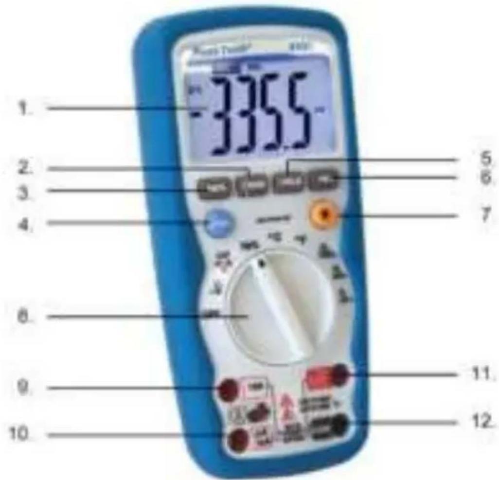
- LCD Anzeige /LCD Display
- Range pushbutton
- Frequency %Duty button
- Mode pushbutton
- Data Hold
- Relative pushbutton
- Backlight pushbutton
- Function switch
- 10A (positive) input jack
- μA/mA (positive) input jack
- Positive input jack for voltage, Hz, Duty cycle, Ohms, Diode, Continuity, Capacitance, and temperature measurements
- COM (negative) input jack
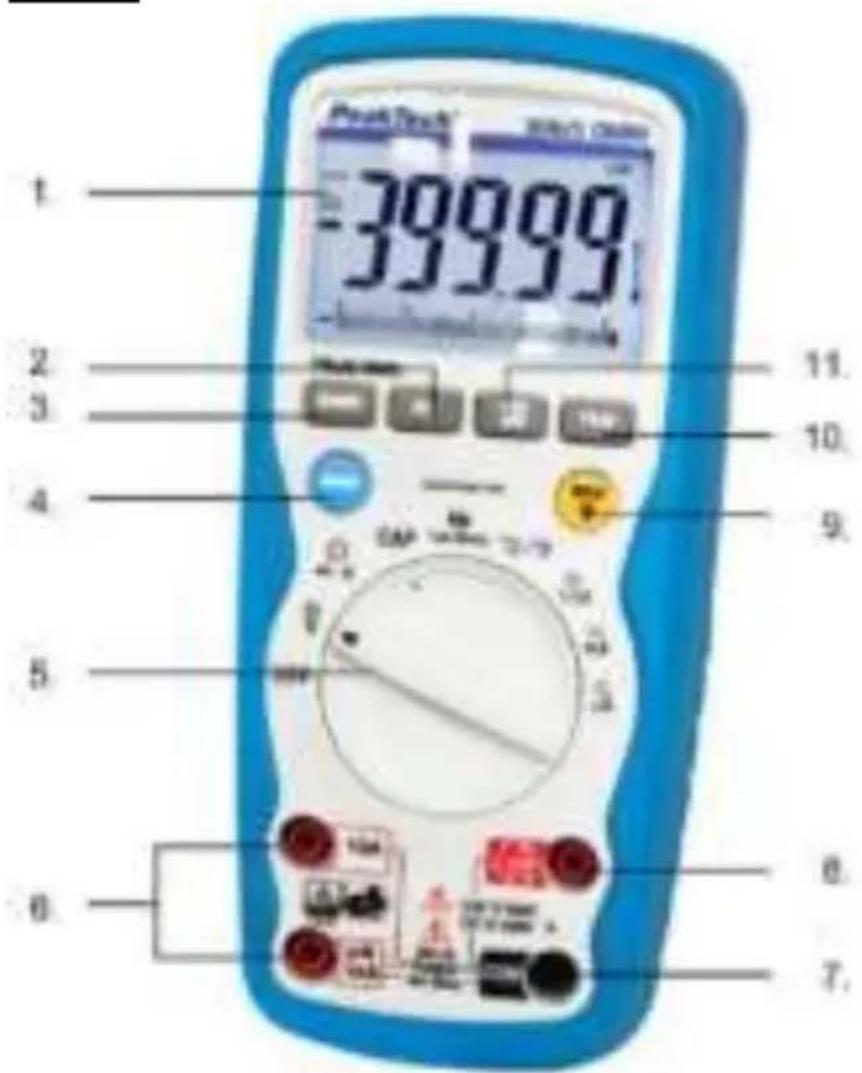
P 3360
text_image
PeakTrack 39999 1 2 3 4 5 6 7 8 9 10 11 20000000000000000000000000000000000000000000000000000000000000000000000000000000000000000000000000000 399999- LCD Display
- Relative pushbutton
- Range pushbutton
- Mode pushbutton
- Function switch
- μA/mA/10 A (positive) input jack
- COM (negative) input jack
- Positive input jack for voltage, Hz, Duty cycle, Ohms, Diode, Continuity, Capacitance, and temperature measurements
- Data Hold and Backlight pushbutton
- PEAK button
- MIN / MAX button
3.1. Symbols in the LCD Display
•))) Continuity ->|- Diode test BAT Battery status n nano (10 -9) μ micro (10 -6) m milli (10 -3)
A current k kilo (10 3) F capacitance (Farads) M mega (10 6) Ω Resistance Hz Frequency % Duty cycle AC Alternating current DC Direct current °F Temperature in Fahrenheit °C Temperature in Centigrade MAX Maximum MIN Minimum PEAK Peak hold V voltage REL Relative AUTO Autoranging HOLD Display hold
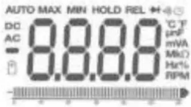
text_image
AUTO MAX MIN HOLD REL + DC 0.0.0.0 °C F AC - 0.0.0.0 μF - 0.0.0.0 mVA - 0.0.0.0 MkΩ - RPM4. Operating instructions
Warning!
Risk of electrocution. High-voltage circuits, both AC and DC are very dangerous and should be measured with great care.
-
Always push the power pushbutton to the OFF position when the meter is not in use. This meter has Auto OFF that automatically shuts the meter OFF if 15 minutes elapse between uses.
-
If "OL" appears in the display during a measurement, that value you are measuring exceeds the range you have selected. Change to higher range.
Note:
On some low AC and DC voltage ranges, with the test leads not connected to a device, the display may show a random, changing reading. This is normal and is caused by the high-input sensitivity. The reading will stabilize and give a proper measurement when connected to a circuit.
- Press the "POWER" pushbutton to turn the meter on and off.
4.1. Autoranging / manual range selection
When the meter is first turned on, it automatically goes into Auto-Ranging. This automatically selects the best range for the measurements being made and is generally the best mode for most measurements. For measurement situations requiring that the range be manually held, perform the following:
- Press the "RANGE" button. The "AUTO" indicator will extinguish and the currently selected range will be held.
- Press the "RANGE" button to step through the available ranges until you select the range you want.
- Press and hold the "RANGE" button for 2 seconds to exit the manual ranging mode and return to "AUTO" mode.
4.2. Backlight
The backlight function is used to illuminate the display when the meter is used at night or in dimly lighted area.
- Press the "HOLD" button (P 3355) or the backlight button (P 3360) for more than 2 seconds, the "HOLD" indicator will appear and backlight will be activated.
Note (P 3360):
The backlight automatically turns off after 30 seconds.
- Press the "HOLD" button momentarily to remove the "HOLD" function. (P 3360).
- Press the "HOLD" button (P 3355) or the backlight button (P 3355) for more than 2 seconds to remove the backlight function.
- Press the "HOLD" button momentarily to remove the "HOLD" function. (P 3360)
4.3 Auto Power Off
The auto power off function will turn the meter off after 15 minutes operation time. To disable this function (only P 3360) press and hold the MODE button and then power on the meter. The display shows “APO d”. To activate the APO function the meter must be power off. Then power on the meter.
5. Measuring
5.1. Relative
The relative measurement feature allows you to make measurements relative to a stored reference value. A reference voltage, current, etc. can be stored and measurements made in comparison to that value. The displayed value is the difference between the reference and the measured value.
- Perform any measurement as described in the operating instructions.
- Press the "REL" button to store the reading in the display and the "REL" indicator will appear on the display.
- The display will now indicate the difference between the stored value and the measured value.
5.2. Data Hold
The data hold function allows the meter to "freeze" a measurement for later reference.
-
Press the "HOLD" button to freeze the display, the "HOLD" indicator will appear in the display.
-
Press the "HOLD" button to return to normal operation.
5.3. Peak function
The PeakTech 3360 offers the "PEAK" function, which records the peak value of an alternating voltage. The meter can have negative or positive peaks lasting a millisecond Capture (1 ms).
- Press the PEAK button and “PEAK” and “MAX” appear in the display. The meter updates this display each time a higher positive peak value occurs.
- Press the PEAK button again and "MIN" appears in the display. The meter updates this display each time a lower positive peak value occurs.
- Press and hold the PEAK button for longer than 1 second to exit "Peak" mode.
The "automatic switch-off" function is automatically deactivated in this mode.
5.4. Minimum and maximum value function
-
Press the MAX / MIN button to activate the maximum value function. The display symbol "MAX" appears. The measuring device shows the maximum display and holds this value until a new maximum value is measured.
-
Press the MAX / MIN button again and the "MIN" symbol appears. The measuring device shows the minimum value display and holds this value until a new minimum value is measured.
-
To exit MAX / MIN mode, press and hold the MAX / MIN button for approx. 2 seconds.
5.5. 4 - 20mA measuring function
4 - 20 mA currents are used as control signals for industrial applications and can be measured with this multimeter.
- Connect the device to the current loop to be measured as described for a mA (milliampere) measurement.
- Set the function switch to the 4-20mA% position
- The meter will display the current loop as a percentage:
$$ 0 \mathrm{mA} = -25 \% $$
$$ 4 \mathrm{mA} = 0 \% $$
$$ 20 \mathrm{mA} = 100 \% $$
$$ 24 \mathrm{mA} = 125 \% $$
5.6. DC Voltage measurements
Caution: Do not measure DC voltages if a motor on the circuit is being switched ON or OFF. Large voltage surges may occur during the ON or OFF operations that can damage the meter.
-
Set the function switch to the "V" position.
-
If "AC" appears in the display, press the "MODE" pushbutton until "DC" appears in the display.
- Insert the black test lead banana plug into the negative COM jack and the red test lead banana plug into the positive V jack.
- Touch the test probe tips to the circuit under test. Be sure to observe the correct polarity (red lead to positive, black lead to negative).
- Read the voltage in the display. The display will indicate the proper decimal point and value. If the polarity is reserved, the display will show (-) minus before the value.
5.7. AC voltage measurements
Warning:
Risk of Electrocution. The probe tips may not be long enough to contact the live parts inside some 230 V outlets for appliances because the contacts are recessed deep in the outlets. As a result, the reading may show 0 volts when the outlet actually has voltage on it. Make sure the probe tips are contacting the metal contacts inside the outlet before assuming that no voltage is present.
Caution:
Do not measure AC voltages if a motor on the circuit is being switched ON or OFF. Large voltage surges may occur during the ON or OFF operations that can damage the meter.
- Set the function switch to the "V" position.
- Press the "MODE" button until "AC" appears in the display.
- Insert the black test lead banana plug into the negative COM jack and the red test lead banana plug into the positive V jack.
- Touch the test probe tips to the circuit under test.
- Read the voltage in the display. The display will indicate the proper decimal point, value and symbol.
5.8. DC current measurement
- Insert the black test lead banana plug into the negative COM jack.
-
For current measurements up to 4000 A DC, set the function switch to the " A" position and insert the red test lead banana plug into the mA- A jack.
-
For current measurements up to 400 mA DC, set the function switch to the "mA" position and insert the red test lead banana plug into the mA- A jack.
-
For current measurements up to 10 A DC, set the function switch to the 10 A position and insert the red test lead banana plug into the 10 A jack.
-
Press the "MODE" button until "DC" appears in the display.
-
Remove power from the circuit under test and open the circuit at the point where you wish to measure current.
-
Touch the black test probe tip to the negative side of the circuit and touch the red test probe tip to the positive side of the circuit.
-
Apply power to the circuit.
-
Read the current in the display. The display will indicate the proper decimal point, value and symbol.
5.9. AC current measurements
Warning:
To avoid electric shock do not measure AC current on any circuit whose voltage exceeds 250 V AC.
- Insert the black test lead banana plug into the negative COM jack.
- For current measurements up to 4000 A AC, set the function switch to the " A" position and insert the red test lead banana plug into the mA- A jack.
- For current measurements up to 400 mA DC, set the function switch to the "mA" position and insert the red test lead banana plug into the mA- A jack.
- For current measurements up to 10 A DC, set the function switch to the 10 A position and insert the red test lead banana plug into the 10 A jack.
- Press the "MODE" button until "AC" appears in the display.
- Remove power from the circuit under test and open the circuit at the point where you wish to measure current.
- Touch the black test probe tip to the negative side of the circuit and touch the red test probe tip to the positive side of the circuit.
- Apply power to the circuit.
- Read the current in the display. The display will indicate the proper decimal point, value and symbol.
5.10. Resistance measurements
Warning:
To avoid electric shock, disconnect power to the unit under test and discharge all capacitors before taking any resistance measurements. Remove the batteries and unplug the line cords.
- Set the function switch to the "OHM" position.
- Insert the black test lead banana jack into the negative COM jack and the red test lead banana plug into the positive jack.
- Touch the test probe tips across the circuit or part under test. It is best to disconnect one side of the part under test so the rest of the circuit will not interfere with the resistance reading.
- Read the resistance in the display. The display will indicate the proper decimal point, value and symbol.
When you short the test leads in the 400 Ω range, your meter display a small value (no more than 0.3 Ω). This value is due to your meter's and test leads internal resistance. Make a note of this value and subtract it from small resistance measurements for better accuracy.
5.11. Continuity check
Warning:
To avoid electric shock, never measure continuity on circuits or wires that have voltage on them.
- Set the function switch to the "OHM" position.
- Insert the black test lead banana jack into the negative COM jack and the red test lead banana-plug into the positive jack.
-
Press the "MODE" push button until the "◀))))" symbol appears in the display.
-
Touch the test probe tips to the circuit or wire you wish to check.
- If the resistance is less than 150 ohms (P 3355) or 35 ohms (P 3360), the audible signal will sound. The display will also show the actual resistance.
5.12. Diode test
Warning:
To avoid electric shock, do not test any diode that has voltage on it.
- Set the function switch to " " position.
- Press the "MODE" button until the "→" symbol appears in the display.
- Insert the black test lead banana plug into the negative COM jack and the red test lead banana plug into the positive jack.
- Touch the test probe tips to the diode or semiconductor junction you wish to test. Note the meter reading.
- Reverse the probe polarity by switching probe position. Note this reading.
- The diode or junction can be evaluated as follows:
A: If one reading shows a value and the other reading show OL, the diode is good.
B: If both readings are OL, the device is open.
C: If both readings are very small or 0, the device is shorted.
Note: The value indicated in the display during the diode check is the forward voltage.
5.13. Frequency / Duty cycle measurement
- Set the function switch to the "Hz" position.
- Insert the black test lead banana jack into the negative COM jack and the red test lead banana plug into the positive Hz jack.
- Touch the test probe tips to the circuit under test.
- Read the frequency in the display. The digital reading will indicate the proper decimal point, symbols (Hz, kHz, MHz) and value.
- Press the "MODE" button to display duty cycle in %.
5.14. Capacitance measurements
Warning:
To avoid electric shock, disconnect power to the unit under test and discharge all capacitors before taking any capacitance measurements. Remove the batteries and unplug the line cords.
- Set the function switch to the "CAP" | position.
- Insert the black test lead banana jack into the negative COM jack and the red test lead banana plug into the positive jack.
- Touch the test leads to the capacitor to be tested. The display will indicate the proper decimal point, value and symbol.
5.15. Temperature measurements
Warning:
To avoid electric shock, disconnect both test probes from any source of voltage before making a temperature measurement.
Insert the adapter in the input socket for temperature measurements.
Insert the K-type thermocouple into the temperature socket, making sure to observe the correct polarity. Touch the temperature probe head to the part whose temperature you wish to measure. Keep the probe touching the part under test until the reading stabilize (about 30 seconds). Read the temperature in the display. The digital reading will indicate the proper decimal point and value.
Warning:
To avoid electric shock, be sure the thermocouple has been removed before changing to any other measurement function.
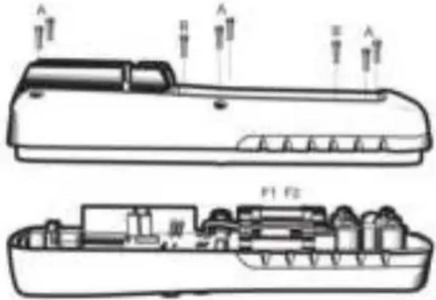
6. Replacing the fuses
WARNING!
To avoid electric shock, disconnect all the test probes before removing the fuse. Replace only with the same type of fuse. Not note remove the top cover. Service should be performed only by qualified personnel.
CAUTION!
For continued protection against fire or other hazard, replace only with fuse of the specified voltage and current ratings.
Follow these steps to replace the fuse:
- Press ON/OFF button to turn the meter off and disconnect the test probes.
- Remove the Battery cover (screws B) and the battery.
- Remover the back cover by unscrewing the 6 screws (A)
- Remove the blown fuse. Use only a fuse with the proper size and value 500mA/1000V (6,3x32mm) or 10A/1000V (10x38mm)
- Replace the back cover, the Battery and the battery cover.
natural_image
Technical line drawing of a device with internal components and labeled parts (no readable text or symbols)WARNING!
Do not operate your meter until the back cover is in place and fully closed.
7. Maintenance
Warning:
To avoid electric shock, disconnect the test leads from any source of voltage before removing the back cover or the battery/fuse door.
Warning:
To avoid electric shock, do not operate your meter until the battery/fuse door are in place and fastened securely. This multimeter is designed to provide years of dependable service, if the following care instructions are performed.
- Keep the meter dry. If it gets wet, wipe it off.
- Use and store the meter in normal temperatures. Temperature extremes can shorten the life of the electronic parts and distort or melt plastic parts.
- Handle the meter gently and carefully. Dropping it can damage the electronic parts or the case.
- Keep the meter clean. Wipe the case occasionally with a damp cloth. Do not use chemicals, cleaning solvents or detergents.
- Use only fresh batteries or the recommended size and type. Remove old or weak batteries so they do not leak and damage the unit.
- If the meter is to be stored for a long period of time, the batteries should be removed to prevent damage to the unit.
8. Troubleshooting
There may be times when your meter does not operate properly. Here are some common problems that you may have and some easy solutions to them.
Meter does not operate:
- Always read all the instructions in this manual before use.
- Check to be sure the battery is properly installed.
- Check to be sure the battery is good.
- If the battery is good and the meter still doesn't operate, check to be sure that both ends of the fuse are properly installed.
9. Replacing the battery
Warning:
To avoid electric shock, disconnect the test leads from any source of voltage before removing the back cover or the battery/fuse door.
- Disconnect the test leads from the meter.
- Open the battery/fuse door by loosening one screw on the battery/fuse door using a screw-driver.
- Clip the new battery into battery holder, observing the correct polarity.
- Place the battery into the battery/fuse compartment.
- Put the battery/fuse door back in place. Secure with the screw.
Warning:
To avoid electric shock, do not operate your meter until the back cover and the battery / fuse door is in place and fastened securely.
Note:
If your meter does not work properly, check the fuses and batteries to make sure that they are still good and that they are properly inserted.
9.1 Notification about the Battery Regulation
The delivery of many devices includes batteries, which for example serve to operate the remote control. There also could be batteries or accumulators built into the device itself. In connection with the sale of these batteries or accumulators, we are obliged under the Battery Regulations to notify our customers of the following:
Please dispose of old batteries at a council collection point or return them to a local shop at no cost. The disposal in domestic refuse is strictly forbidden according to the Battery Regulations. You can return used batteries obtained from us at no charge at the address on the last side in this manual or by posting with sufficient stamps.
Contaminated batteries shall be marked with a symbol consisting of a crossed-out refuse bin and the chemical symbol (Cd, Hg or Pb) of the heavy metal which is responsible for the classification as pollutant:
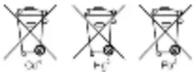
chemical
Three identical chemical structures with crosshairs, labeled Oa², H₂², and Fb², likely representing oxygen and hydrogen atoms in a mechanical or chemical model.- "Cd" means cadmium.
- "Hg" means mercury.
- "Pb" stands for lead.
All rights, also for translation, reprinting and copy of this manual or parts are reserved.
Reproduction of all kinds (photocopy, microfilm or other) only by written permission of the publisher.
This manual considers the latest technical knowing. Technical changings which are in the interest of progress reserved.
We herewith confirm, that the units are calibrated by the factory according to the specifications as per the technical specifications. We recommend to calibrate the unit again, after 1 year.
chemical
Three chemical reaction diagrams showing different mechanical or structural configurations with crossed and unconnected arrows indicating direction- "Cd" signifie cadmium.
- "Hg" signifie mercure.
- "Pb" signifie plomb.
text_image
O0' H1' F0'© PeakTech®09/2020/Ho/Pt./Mi/Ehr.