
ZMH6WCLX - Cooker ZEROWATT - Free user manual and instructions
Find the device manual for free ZMH6WCLX ZEROWATT in PDF.

| Product Type | Gas Cooker |
| Brand | Zerowatt |
| Model | ZMH6WCLX |
| Dimensions (W x D) | 595 x 510 mm |
| Power Supply | 220-240 V ~ 50/60 Hz |
| Electrical Power | 1 W (electronic ignition) |
| Gas Type | G20 (methane) / G30 (butane/propane) |
| Number of Burners | 4 |
| Auxiliary Burner (1 kW) | 1 |
| Semi-rapid Burner (1.75 kW) | 2 |
| Rapid Burner (2.7 kW) | 1 |
| Total Gas Power | 7.2 kW |
| Integrated Electronic Ignition | Yes |
| Thermocouple Safety | Yes (FFD) |
| Minimum Flame Adjustment | Yes |
| Table Material | Stainless steel / enamel |
| Grills | Chrome-plated |
| Care and Cleaning | Warm soapy water, avoid abrasive products |
| Child Safety | Child lock not specified, supervision required |
| Spare Parts | Available via after-sales service |
| Installation | Built-in or freestanding, by qualified professional |
Frequently Asked Questions - ZMH6WCLX ZEROWATT
User questions about ZMH6WCLX ZEROWATT
0 question about this device. Answer the ones you know or ask your own.
Ask a new question about this device
Download the instructions for your Cooker in PDF format for free! Find your manual ZMH6WCLX - ZEROWATT and take your electronic device back in hand. On this page are published all the documents necessary for the use of your device. ZMH6WCLX by ZEROWATT.
USER MANUAL ZMH6WCLX ZEROWATT
MATERIALS IN COMPLIANCE WITH REQUIREMENTS OF EU DIRECTIVE 2002/95/CE + AMENDMENTS
ALL RIGHTS RESERVED, THE REPRODUCTION OF ANY PART WITHOUT OUR WRITTEN CONSENT IS FORBIDDEN
| RELEASE LEVEL | |||||||||
| PRODUCTION RELEASED | |||||||||
| (H) | |||||||||
| (G) | |||||||||
| (F) | |||||||||
| (E) | |||||||||
| 57648 | (D) | 29.02.21 | 1.1 Montaj böümünde paragraf güncellendi/Paragraph was updated in 1.1 Building in section. | Y.GÜLTÜRK | |||||
| CL N° REV. DATE | MODIFY DESCRIPTION | MODIFIED BY | |||||||
| SPECIFICATION | DATE SIGNATURE | PROPERTY OF CANDY·HOOVER GROUP | |||||||
| GENERAL TOLERANCEISO 2768 - m | DRAWN29.0 .20212 Y.GÜLTÜRK | ||||||||
| CHECKED29.0 .20212 - | NAMEUSER MANUAL IT-FR-ENG. LAT ZER | ||||||||
| BASE CODE | FORHOB | (LOCAL LANGUAGE)KULLANMA KILAVUZU IT-FR-ENG. LAT ZER | |||||||
| - | |||||||||
| WEIGHT SCALE | PART CODE | SHEET | |||||||
| TREATMENT | Kg. | 1:1 | 4 2 8 2 8 0 2 9 | 1/1 | |||||
| Printing ColorGrey Scala | |||||||||
| MATERIAL | SIZE | REPLACE No ORIGIN CL No Class Specification | |||||||
| White Paper52 gr/m - 70 gr/m | A4 | ---- | ---- | XXXXX | SC 000-000 | ||||
ZEROWATT
HOBS
USER INSTRUCTIONS GB 02
TABLES DE CUISSON
NOTICE D'EMPLOI FR 06
PIANI COTTURA
ISTRUZIONI PER L'USO IT 10
natural_image
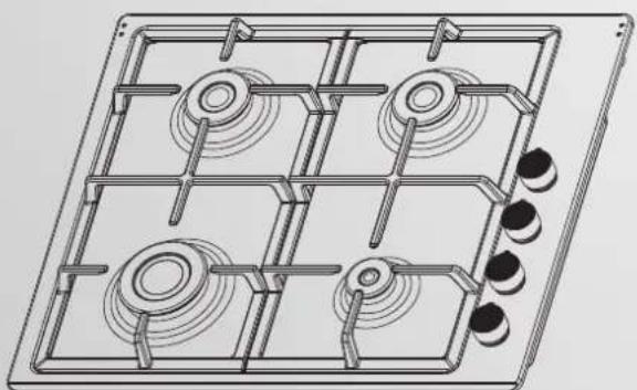
Technical line drawing of a mechanical grid with four circular components and connecting rods (no text or symbols)SAFETY INSTURUCTIONS
We recommend you keep the i nstructi ons for i installati on and use for later reference, and before i installi ng the hob, note i ts seri al number i n case you need to get help from the after sales servi ce.
WARNING: the appli ance and i ts accessi ble parts become hot during use. Care should be taken to avoid touching heating elements. Children under 8 years of age must be kept away from the appli ance unless they are conti nuously supervi sed.
WARNING: use only hob guards designed by the Manufacturer of the cooking appliance or indicated by the Manufacturer of the appliance in the instructions for use as suitable or hob guards incorporated in the appliance. The use of inappropriate guards can cause accidents.
WARNING: unattended cooking on a hob with fat or oil can be dangerous and may result in fire. NEVER try to extinguish a fire with water, but switch off the appliance and then cover flame e.g. with a lid or a fire blanket.
WARNING: danger of fire: do not store i tems on the cooking surfaces.
WARNING: i f the surface i s cracked, do not touch the glass and swi tch off the appli ance to avoi d the possi bi li ty of electri c shock.
This appliance can be used by chi ldren aged from 8 years and above and people with reduced physical, sensory or mental capabilities or lack of experience and knowledge if they have been given supervision or instruction concerning use of the appliance in a safe way and understand the hazards involved. Children should be supervised to ensure that they do not play with the appliance. Cleaning and user maintenance shall not be made by chi ldren with out supervis on.
CAUTION: the cooki ng process must be supervi sed. A short term cooki ng process has to be supervi sed conti nuously.
It is strongly recommended to keep chi ldren away from the cooking zones while they are in operation when they are switched off, so long as the residual heat indicator is on, in order to prevent the risks of serious burns.
This appliance is not intended to be operated by means of an external timer or separate remote control system.
If present do not to stare into halogen lamp hob elements.
Connect a plug to the supply cable that is able to bear the voltage, current and load i ndi cated on the tag and hav i ng the earth contact. The socket must be suitable for the load indicated on the tag and must be having the earth contact connected and i n operati on. The earth conductor i s yellow-green
i n color. Thi s operati on should be carri ed out by a sui tably quali fi ed professi onal. In case of incompati bi li ty between the socket and the appliance plug, ask a qualified electrician to
substitute the socket with another suit table type. The plug and the socket must be conformed to the current norms of the installati on country. Connecti on to the power source can also be made by placing an omnipolar breaker between the appli ance and the power source that can bear the maximum connected load and that is in line with current legi slati on.
The yellow-green earth cable should not be interrupted by the breaker. The socket or omni polar breaker used for the connection should be easily accessible when the appliance is installed.
The disconnecti on may be achi eved by hav i ng the plug accessi ble or by i ncorporati ng a sw i tch i the fixed wiring in accordance with the wiring rules.
If the supply cord i s damaged, i t must be replaced by Manufacturer, its service agent or similarly qualified people in order to avoid a hazard. The earth conductor (yellow-green) must be longer than 10 mm on the terminal block si de. The i nternal conductors secti on should be appropriate to the power absorbed by the hob (indicated on the tag). The type of power cable must be HO5V2V2-F.
Do not put metalli c objects such as kni ves, forks, spoons or li ds on the hob. They could heat up. Alumi num foi l and plasti c pans must not be placed on heating zones.
After every use, some cleaning of the hob is necessary to prevent the bui ld-up of di rt and grease. If left, this is recooked when the hob is used and burns gi vi ng off smoke and unpleasant smells, not to menti on the ri sks of fi re propagati on.
Never use a steam or high pressure spray to clean the appli ance.
Do not touch the heat zones during operation or for a while after use.
Never cook food directly on the glass ceramic hob.
Always use the appropriate cookware. Always place the pan i n the center of the uni t that you are cooking on.
Do not place anything on control panel.
Do not use the hob as a working surface.
Do not use the surface as a cutting board.
Do not store heavy items above the hob. If they drop onto the hob, they may cause damage.
Do not use the hob for storage of any i tems.
Do not sli de cookware across the hob.
No additional operation/setting is required in order to operate the appli ance at the rated frequenci es
1. INSTRUCTIONS FOR THE INSTALLER
INSTALLING A DOMESTIC APPLIANCE CAN BE A COMPLICATED OPERATION WHICH IF NOT CARRIED OUT CORRECTLY, CAN SERIOUSLY AFFECT CONSUMER SAFETY. IT IS FOR THIS REASON THAT THE TASK SHOULD BE UNDERTAKEN BY A PROFESSIONALLY QUALIFIED PERSON WHO WILL CARRY IT OUT IN ACCORDANCE WITH THE TECHNICAL REGULATIONS IN FORCE. IN THE EVENT THAT THIS ADVICE IS IGNORED AND THE INSTALLATION IS CARRIED OUT BY AN UNQUALIFIED PERSON, THE MANUFACTURER DECLINES ALL RESPONSIBILITY FOR ANY TECHNICAL FAILURE OF THE PRODUCT WHETHER OR NOT IT RESULTS IN DAMAGE TO GOODS OR INJURYTO INDIVIDUALS.
1.1 BUILDING IN
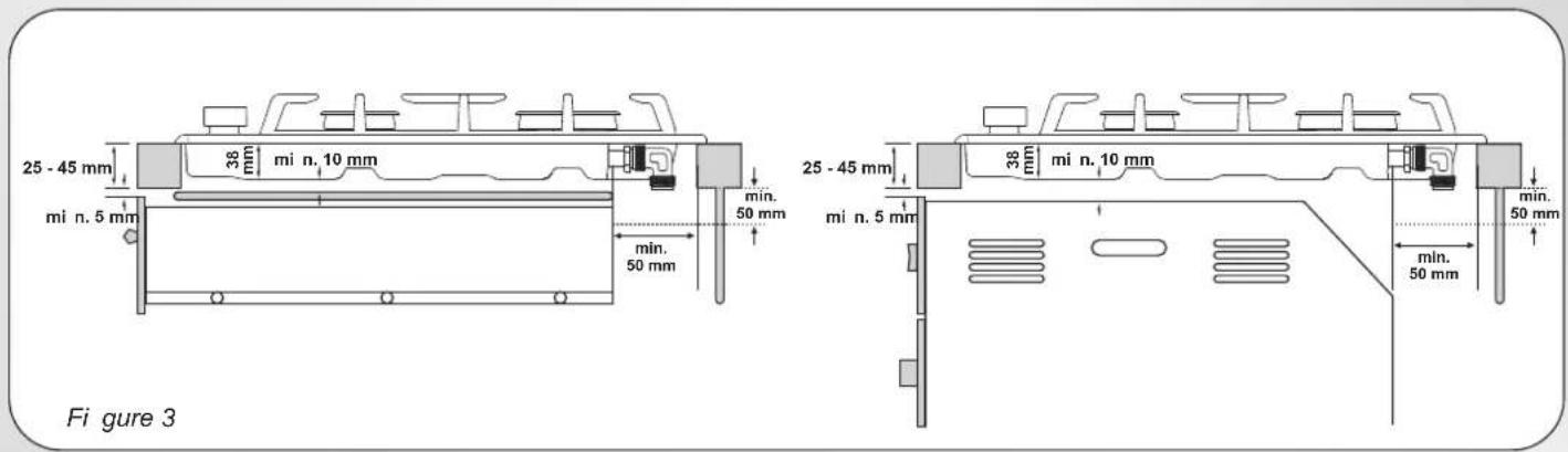
The hob may be installed in any worktop which is heat resistant to a temperature of 100^ C, and has a thickness of 25-45 mm. The dimensions of the insert to be cut out of the worktop are in shown in Figure 2.
When there is an accessible space between the built-in hob and the cavity below, a dividing wall made of insulating material should be inserted (wood or a similar material) (Figure 3).
If the hob is fitted next to a cabinet on either side, the distance between the hob and the cabi net must be at least 15 cm; whi le the di stance between the cut out and the rear wall must be at least 7 cm.
The distance between the hob and any other unit or appliance above i (e.g. An extractor hood) must be no less than 70 cm . (Fi gure 4)
Metal objects in the drawer may reach high temperatures due to air recirculation. It is therefore recommended to use an intermediate wood panel.
Important - The diagram in figure 1 shows how the sealant should be applied.
The Hob unit is fitted by attaching the Fixing Clamps supplied, using the holes at the base of the uni t.
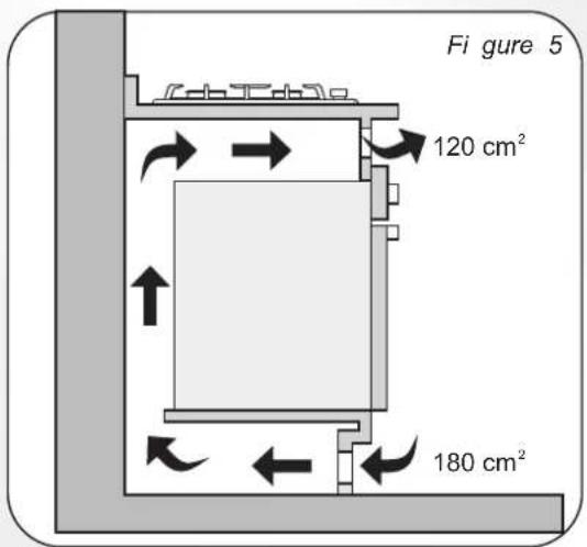
If a hob of 60 cm is fitted above an oven which is not equipped with fan cooling system it is recommended that openings are created within the built in furniture to ensure correct air circulation.
The size of these openings must be at least 300 cm2 and placed as shown in Figure 5.
1.2. SUITABLE LOCATION
This appliance must be installed in accordance with the regulations in force and only used in a well ventilated space. Read the instructions before installing or using this appliance.
A gas-powered cooking appliance produces heat and humidity in the area in which it is installed. For this reason you should ensure good ventilation either by keeping all natural air passages open or by installing an extractor hood with an exhaust flue. Intensive and prolonged use of the appliance may require extra ventilation, such as the opening of a window or an increase in speed of the electric fan, if you have one.
If a hood can not be installed, an electric fan should be fitted to an outside wall or window to ensure that there is adequate ventilation. The electric fan should be able to carry out a complete change of air in the kitchen 3-5 times every hour. The installer should follow the relevant national standards.
2. ELECTRICAL CONNECTION (FOR U.K. ONLY)
Warning - this appliance must be earthed
This appliance is designed for domestic use only. Connection to the main supply must be made by a competent electrician, ensuring that all current regulations concerning such installations are observed.
The appli ance must only be connected to a sui tably rated spur poi nt, a 3 p i n 13 amp plug/socket i s not sui table. A double pole swi tch must b provided and the circuit must have appropriate fuse protection. Further details of the power requirement of the individual product will be found in the users' instruction and on the appliance rating plate. In the case of built-in product you are advised, should you wish to use a longer cable than the one suppli ed, that a sui tably rated heat resi stant type must be used.
The wi ri ng must be connected to the mai ns supply as follows:
CONNECT
TO SPUR TERMINAL
Green & Yellow Wire
Earth Connection
Blue Wi re
Neutral Connection
Brown Wi re
Li ve Connecti on
Note: We do not advocate the use of earth leakage devices with electric cooking appliances installed to spur points because of the «nuisance tripping» which may occur. You are again reminded that the appliance must be correctly earthed, the manufacturer declines any responsibility for any event occurring as a result of incorrect electrical installation.
2.1. ELECTRICAL CONNECTION
Check the data on the rating plate, located on the outside of the unit, to ensure that the supply and input voltage are suitable.
Before connection, check the earthi ng system.
By Law, this appliance must be earthed. If this regulation is not complied with, the Manufacturer will not be responsible for any damage caused to persons or property. If a plug is not already attached, fit a plug appropriate to the load indicated on the rating plate. The earth wire is coloured yellow/green. The plug should always be accessible.
Where the Hob is connected direct to the electricity supply, a circuit breaker must be fitted.
If the power supply cord is damaged this is to be replaced by a qualified engineer so as to prevent any potential risk.
The earth wire (green and yellow coloured) must be at least 10 mm longer than the line and neutral wires.
The section of the cable used must be of the correct size in relation to the absorbed power of the hob.
Please check rating plate for the power details and ensure that the power supply cord is of the type 3x0.75 mm² H05 V2V2-F.
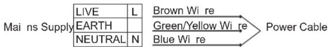
flowchart
graph LR
    A["LIVE"] --> B["EARTH"]
    B --> C["NEUTRAL"]
    D["Brown Wi re"] --> E["Green/Yellow Wi re"]
    E --> F["Blue Wi re"]
    F --> G["Power Cable"]
If an appliance is not fitted with a supply cord and a plug, or with other means for disconnecti on from the supply mai ns hav i ng a contact separati on i n all poles that provi de full di sconnecti on under overvoltage category III conditions, the instructions shall state that means for disconnection must be incorporated in the fixed wiring in accordance with the wi ri ng rules.
2.2. GAS CONNECTION
These instructions are for qualified personnel, installation of equipment must be in line with the relevant national standard. (For U.K. only: by law the gas installation\commissioning must be carried out by a "Gas Safe" installer)
All work must be carried out with the electricity supply disconnected. The rating plate on the hob shows the type of gas with which it is designed to be used. Connection to the mains gas supply or gas cylinder should be carried out after having checked that it is regulated for the type of gas with which it will be supplied. If it is not correctly regulated see the instructions in the following paragraphs to change gas setting.
For liquid gas (cylinder gas) use pressure regulators which comply with the relevant national standards.
Use only pipes, washers and sealing washers which comply with the relevant national standards.
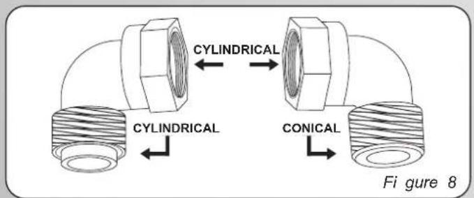
^e For some models a conic link is furnished to outfit for the installation in the countries where this type of link is obligatory; in picture 8 it is pointed out how to recognize the different types of links (CY = cylindrical, CO = conic). In every case the cylindrical part of the link has to be connected to the hob.
When connecting the hob to the gas supply via use offlexible hoses please ensure that the maximum distance covered by the hose does not exceed 2 metres.
The flexible tube shall be fitted in such a way that it cannot come into contact with a moveable part of the housing unit (e.g. a drawer) and does not pass through any space where it may become crushed/ kinked or damaged in any way.
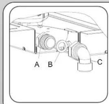
To prevent any potential damage to the hob please carry out the installati on following this sequence (picture 6):
1) As i illustrated, assemble parts i n sequence:
A: 1/2 MaleAdaptor Cyli ndi ri cal
B: 1/2 Seal
C: 1/2 Female Gas Adaptor Conical-Cylindrical or Cylindrical-Cylindrical
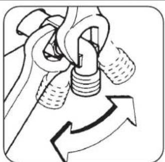
2) Tighten the joints with the spanner, remembering to twist the pipes into position.
3) Attach fitting C to mains gas supply using rigid copper pipe or flexible steel pipe.
IMPORTANT: carry out a final check for leaks on the pipe connections using a soapy solution. NEVER USE A FLAME. Also, make sure that the flexible pipe cannot come into contact with a moving part of the cabinet (eg.adrawer) and that it is not situated where it could be damaged.
Warning: If gas can be smelt in the vicinity of this appliance turn off the gas supply to the appliance and call the engineer directly. Do not search for a leak with a naked flame.
2.3. ADAPTING THE HOB TO DIFFERENT TYPES OF GAS
To adapt the Hob for use with different types of gas, carry out the following instructions:
- Remove the grids and burners
- Insert on hexagonal spanner (7 mm) into the burner support (Figure 7)
- Unscrew the injector and replace it with one suitable for the gas to be used (see gas type table)
2.4. REGULATING THE MINIMUM FLAME
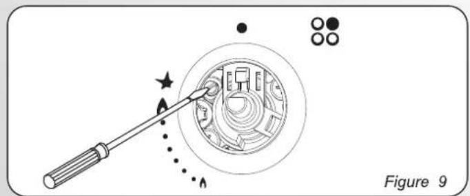
After lighting the burners, turn the control knob to the minimum setting and then remove the knob (this can easily be removed by applying gentle pressure).
Using a small «Terminal» type screwdriver the regulating screw can be adjusted as in Figure 9. Turning the screw clockwise reduces the gas flow, whilst turning it anticlockwise increases the flow – Use this adjustment to obtain a flame of approximately 3 to 4 mm in length and then replace the control knob.
When the gas supply available is LPG - the screw to set the idle flame must be turned (clockwise) to the end stop.
When you have carried out the new gas regulation, replace the old gas rating plate on your appliance with one (supplied with hob) suitable for the type of gas for which it has been regulated.
3. USE OF HOB - USER INSTRUCTIONS
This appliance must only be used for the purpose for which it is intended, domestic cooking, and any other use will be considered improper and could therefore be dangerous. The Manufacturer will not be responsible for any damage or loss resulting from improper use.
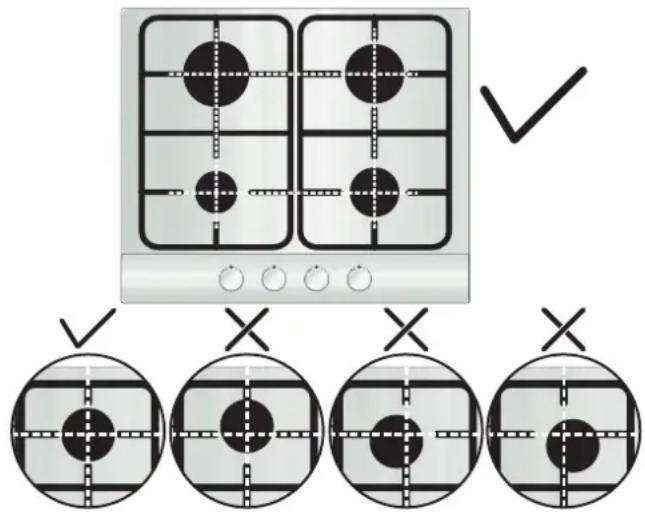
Before using burner, be sure, grid peri meters center the burner as below figure.
If you are using Cast Iron Grids; underneath the grid, position of it is stated. Be sure for the exact grid is used in correct position.
To ignite the burners, place a lighted taper close to the burner, press in and turn the control knob anti -clockwise.
If the burners have not been used for a couple of days, wait for a few seconds before lighting the burner, this will allow any air present in the pipes to escape.
For appliances fitted with electronic ignition carry out the following:
- Push in and turn the knob anticlockwise to the ignition symbol.
- Igni te the burner by pressi ng the sparker button.
For hobs fitted with automatic ignition simply push in and turn the knob to the i gni ti on symbol.
The ignition system will continue to generate sparks as long as the control knob is being pressed.
If the burner has not ignited within 5 seconds, turn the knob to the 0 posi ti on and repeat the operati on.
For models fitted with a safety tap (which cuts-off the flow of gas if the flame is accidentally extinguished) the burners are ignited and described above, but care must be taken.
Prior to switching on the gas hob ensure that the burners and burner caps are correctly placed within their position.
Warning: If there is no electricity on appliance, to ignite the burner a lighter should be used;
- Push in and turn the knob anti-clockwise to the ignition symbol,
- While pushing in the button ignite the burner by using a lighter and keep button pushed in 5 seconds after ignition.
GENERALADVISE
For best results, use cooking vessels with a flat surface. The size of the surface should match the gas burner side as follows. Table A.
| Burner Type | ∅ pan/pot (cm) | Power (kW) | G20/20 mbar (methane) | G30/28-30 mbar (LPG) |
| AUX Auxi li ary | 10 - 18 | 1,00 | 95 l/h | 73 g/h |
| SR Semi Rapi d | 12 - 22 | 1,75 | 167 l/h | 127 g/h |
| R Rapi d | 16 - 26 | 2,70 | 257 l/h | 196 g/h |
Table A
For smaller containers the gas burner should be regulated so that the flame does not overlap the base of the pan. Vessels with a concave or convex base should not be used.
WARNING: If a flame is accidentally extinguished, turn the knob to the off position and do not attempt to re-ignite if for at least 1 minute.
If over the years the gas taps become stiff to turn it is necessary to lubricate them.
Such operation must be carried out only by qualified Service Engineers.
4. MAINTENANCE AND CLEANING
Before cleaning the hob, ensure the appliance has cooled down. Remove the plug from the socket or (if connected directly) switch off the electricity supply.
Cleaning and user maintenance shall not be made by children without supervi si on
Never use abrasives, corrosive detergents, bleaching agents or acids. Avoid any acid or alkaline substances (lemon, juice, vinegar etc.) on the enamelled, varni shed or stai nless steel secti ons.
When cleaning the enamelled, varni shed or chrome sections, use warm soapy water or a non caustic detergent. For stainless steel use an appropriate cleaning solution.
The burners can be cleaned with soapy water. To restore their original shi ne, use a household stai nless steel cleaner. After cleani ng, dry the burners and replace.
It is important the Burners are replaced correctly.
Chromed grids and burners
Chromed grids and burners have a tendency to discolour with use. This does not jeopardize the functionality of the hob.
Our After Sales Service Centre can provide spare parts if required.
5. AFTERCARE
Before calling out a Service Engineer please check the following:
- that the plug is correctly inserted and fused;
• that the gas supply is not faulty.
If the fault cannot be detected:
Switch off the appliance and call the After Service Centre. DO NOT TAMPER WITH THE APPLIANCE.

By placing the mark on this product, we are confirm compli ance to all relevant European safety, health and environmental requirements which are applicable in legislation for this product.
The Manufacturer will not be responsible for any inaccuracy resulting from printing or transcript errors contained in this brochure. We reserve the right to carry out modifications to products as required, including the interests of consumption, without prejudice to the characteristics relating to safety or function.
6. PROTECTION OF THE ENVIRONMENT
This appliance is marked according to the European di recti ve 2012/19/EU on Waste Electri cal and Electronic Equipment (WEEE). WEEE contains both polluti ng substances (whi ch can cause negati ve consequences for the environment) and basi c components (whi ch can be re-used). It i si important to have WEEE subjected to speci fi c treatments, i n order to remove and di spose properly all pollutants, and recover and recycle all materials.
Individuals can play an important role in ensuring that WEEE does not become an environmental issue; it is essential to follow some basic rules:
- WEEE shall not be treated as household waste.
- WEEE shall be handed over to the relevant collecti on points managed by the municipality or by registered companies. In many countries, for large WEEE, home collecti on could be present.
- When you buy a new appliance, the old one may be returned to the retailer who has to collect it free of charge on a one-to-one basis, as long as the equipment is of equal valent type and has the same functions as the supplied equipment.
Declaration of compliance: This equipment, in the parts intended to come into contact with food, complies with the regulations laid down in EEC di recti ves 89/109.
The appli ance compli es wi th European Di recti ve 2009/142/EC (GAD) and starti ng from 21/04/2018 wi th Gas Appli ances Regulati on 2016/426 (GAR).
Table 1
| Burner Plate | 4 Gas |
| Burner | Aux/2SR/R |
| Type | UH60ML |
| FFD | YES |
| Aux 1kW | 1 |
| Sr 1,75 kW | 2 |
| R 2,7 kW | 1 |
| Nominal Heat Input | 7,2 kW |
| G20/20 mbar | 686 l/h |
| G30/28-30 mbar | 524 g/h |
| Installation Class | 3 |
| Voltage V/Frequency Hz | 220-240 V/ 50/60 Hz |
| Electrical Input Power | 1 |
| Electric Ignition | YES |
| Product Dimension | 595x510 |
This appliance has been designed for non-professional, i.e. domestic, use.
CONSIGNES DE SÉCURITÉ
natural_image
Exterior view of a rectangular electronic device with multiple slots and a small knob (no text or symbols visible)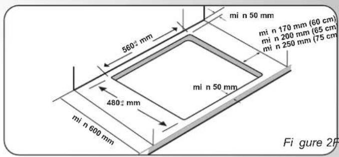

natural_image
Diagram of a rope knot with directional arrows indicating motion (no text or symbols)
natural_image
Technical line drawing of a mechanical joint or connector (no text or symbols)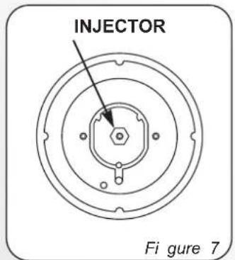
natural_image
Diagram showing a tool interacting with a circular device, with no visible text or symbols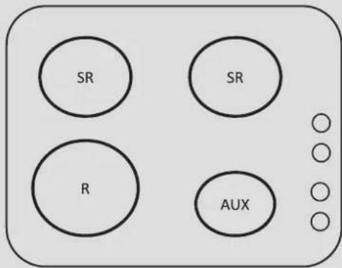
GAS TYPEHOBS
| Gas Type | G20 | G20 | G25.1 | G25.3 | G30 | G30 | G30 | |||
| Gas Pressure | 20 mbar | 25 mbar | 25 mbar | 25 mbar | 29 mbar | 37 mbar | 50 mbar | |||
| Burners | Max (kW) | Min (kW) | Injector NG | Injector NG | Injector NG | Injector NG | Injector LPG | Injector LPG | Injector LPG | |
| Max - Min Max - Min Max - Min Max - Min Max - Min Max - Min Max - Min Max - Min | ||||||||||
| Aux | 1 | 0,3 | 72X(1Kw-0,3Kw) | 70X(1Kw-0,3Kw) | 74F1(1Kw-0,3Kw) | 72F1(1Kw-0,3Kw) | 50(1Kw-0,3Kw) | 46(1Kw-0,34Kw) | 43H2(1Kw-0,39Kw) | |
| Sr | 1,75 | 0,44 | 97Z(1.75Kw-0.44Kw) | 91Z(1.75Kw-0.44Kw) | 98Y(1.75Kw-0.44Kw) | 102F3(1.75Kw-0.44Kw) | 65(1.75Kw-0.44Kw) | 61(1.75Kw-0.51Kw) | 58M(1.75Kw-0.58Kw) | |
| R | 2,7 | 0,75 | 109Y(2.7Kw-0.75Kw) | 110F3(2.7Kw-0.75Kw) | 125F3(2.7Kw-0.75Kw) | 120F3(2.7Kw-0.75Kw) | 80(2.7Kw-0.75Kw) | 78(2.7Kw-0.83Kw) | 73S(2.7Kw-0.96Kw) | |
| Gas Categories | II2E+3+ | II2H3+ | II2H3B/P |
| G20/G25-20/25 mbar | G20 20 mbar | G20 20 mbar | |
| G30/31 28-30/37 mbar | G30 28-30mbar | G30/31 30/30 mbar | |
| G31 37 mbar | |||
| Countries | BE,FR | CY,CZ,GB,GR,IE,IT,PT,SI, ES,TR,CH | BG, HR,DK,EE,FI,LV,LT,NO,RO,SK,SE,CZ,SI,TR |
| Gas Categories | II2H3B/P | II2EK B/P3 | II2HS3B/P | II2E3B/P | II2E3B/P |
| G20 20 mbar | G20 20 mbar | G20 25mbar | G20 20 mbar | G20 20 mbar | |
| G30/31 50/50 mbar | G25.3 25 mbar | G25.1 25 mbar | G30/31 37/37 mbar | G30/31 50 mbar | |
| G30/31 30/30 mbar | G30/31 30/30 mbar | ||||
| Countries | AT,CH | NL | HU | PL | DE |
Efficiency Declaration 201 /4 66/EU
| EN 30-2-1 | |||
| UH60ML | |||
| SINGLE BURNER EFFICENCY | |||
| AUX FR SR RR SR RL R FL | |||
| - | 60 % 60 | % 57,6 % | |
| MEDIUM %59,2 | |||

GB - IE
The manufacturer will not be responsible for any inaccuracy resulting from printing or transcript errors contained in this brochure. We reserve the right to carry out modifications to products as required, including the interests of con sumption, without prejudice to the characteri stics relating to safety or function.
FR

- ZEROWATT
- HOBS
- TABLES DE CUISSON
- PIANI COTTURA
- SAFETY INSTURUCTIONS
- INSTRUCTIONS FOR THE INSTALLER
- BUILDING IN
- SUITABLE LOCATION
- ELECTRICAL CONNECTION (FOR U.K. ONLY)
- Warning - this appliance must be earthed
- CONNECT
- TO SPUR TERMINAL
- ELECTRICAL CONNECTION
- GAS CONNECTION
- 1) As i illustrated, assemble parts i n sequence:
- ADAPTING THE HOB TO DIFFERENT TYPES OF GAS
- REGULATING THE MINIMUM FLAME
- USE OF HOB - USER INSTRUCTIONS
- GENERALADVISE
- MAINTENANCE AND CLEANING
- Chromed grids and burners
- AFTERCARE
- PROTECTION OF THE ENVIRONMENT
- CONSIGNES DE SÉCURITÉ
- GB - IE
- FR
Brand : ZEROWATT
Model : ZMH6WCLX
Category : Cooker