
TR2430 - Temperature sensor amplifier IFM - Free user manual and instructions
Find the device manual for free TR2430 IFM in PDF.
| Product type | Temperature sensor amplifier |
| Brand | IFM |
| Model | TR2430 |
| Power supply | 20...30 V DC |
| Current consumption | < 66 mA |
| Sensor constant current | 385 μA (Pt 1000) |
| Measuring range | -40...+150 °C (-40...+302 °F) |
| Display | Digital, 2 digits, resolution 0.5 °C/°F, adjustable orientation |
| Output 1 (switching) | Transistor, 250 mA, functions: Hno, Hnc, Fno, Fnc |
| Output 2 (analog) | 4...20 mA or 0...10 V, adjustable |
| Switching output accuracy | ±0.2 °C / ±0.36 °F |
| Analog output accuracy | ±(0.2 °C + 0.4% of measuring span) |
| Protection | IP 67, reverse polarity, short-circuit, overload |
| Ambient temperature | -25...+70 °C |
| Storage temperature | -40...+85 °C |
| Housing material | NOX 304, EPDM/X, PC, PBTP, FPM |
| Connection | M12 male connector, colors: brown, white, blue, black |
| Main functions | Temperature measurement, display, 2 outputs, hysteresis, window, min/max memory, zero calibration |
| Maintenance | No maintenance required |
| Safety | Installation by electrician, compliance with national and international standards |
Frequently Asked Questions - TR2430 IFM
User questions about TR2430 IFM
0 question about this device. Answer the ones you know or ask your own.
Ask a new question about this device
Download the instructions for your Temperature sensor amplifier in PDF format for free! Find your manual TR2430 - IFM and take your electronic device back in hand. On this page are published all the documents necessary for the use of your device. TR2430 by IFM.
USER MANUAL TR2430 IFM
M=Mode/Enter
S = Set
Programmieren / Programming / Programmation
| 1 | 1 x Mode/Enter Set 2 x | → SP10 | Parameter aufrufen Select parameters Sélectionner les paramètres |
| 2 | 1 s Mode/Enter Set > 5 s | → P10 | Werte einstellen* Set Values* Régler la valeurs* |
| 3 | 1 x Mode/Enter Set 1 x | → SP10 | Werte bestätigten Acknowledgement of values Confirmer la valeur |
Wert verringn: Lassen Sie die Anzeige bis zum maximalen Einstellwert laufen. Danach beginnt der Durchlauf wieder beim minimalen Einstellwert.
Decrease the value: Let the display of the parameter value move to the maximum setting value. Then the cycle starts again at the minimum setting value.
*Réduire la valeur du paramètre: Laisser l'affichage de la valeur du paramètre aller jusqu'à la valeur de réglage maximum. Ensuite le cycle recommence à la valeur de réglage minimum.
1. Controls and visual indication
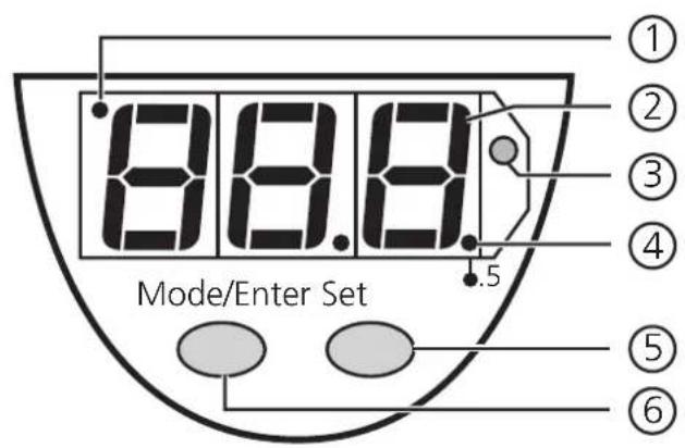
| ① | Indicator for display unit | OFF = indication in °C; ON = indication in °F |
| ② | 7-segment display | display of the system temperature, display of parameters and parameter values |
| ③ | LED red | switching status; lights if the output has switched |
| ④ | LED red LED | ON = displayed temperature + 0.5° |
| ⑤ | Set button | setting of the parameter values (scrolling by holding pressed; incremental by pressing briefly) |
| ⑥ | Mode / Enter button | selection of the parameters and acknowledgement of the parameter values |
2. Functions and features
- The unit detects current system temperature from temperature sensors TS or TT,
- shows the current system temperature on its display (in ° C or ° F ),
- and generates 2 output signals according to the set output configuration.
| output 1 | output 2 |
| hysteresis function / N.O. (Hno) | analog 4 ... 20 mA (I) |
| hysteresis function / N.C. (Hnc) | |
| window function / N.O. (Fno) | analog 0 ... 10 V (U) |
| window function / N.C. (Fnc) |
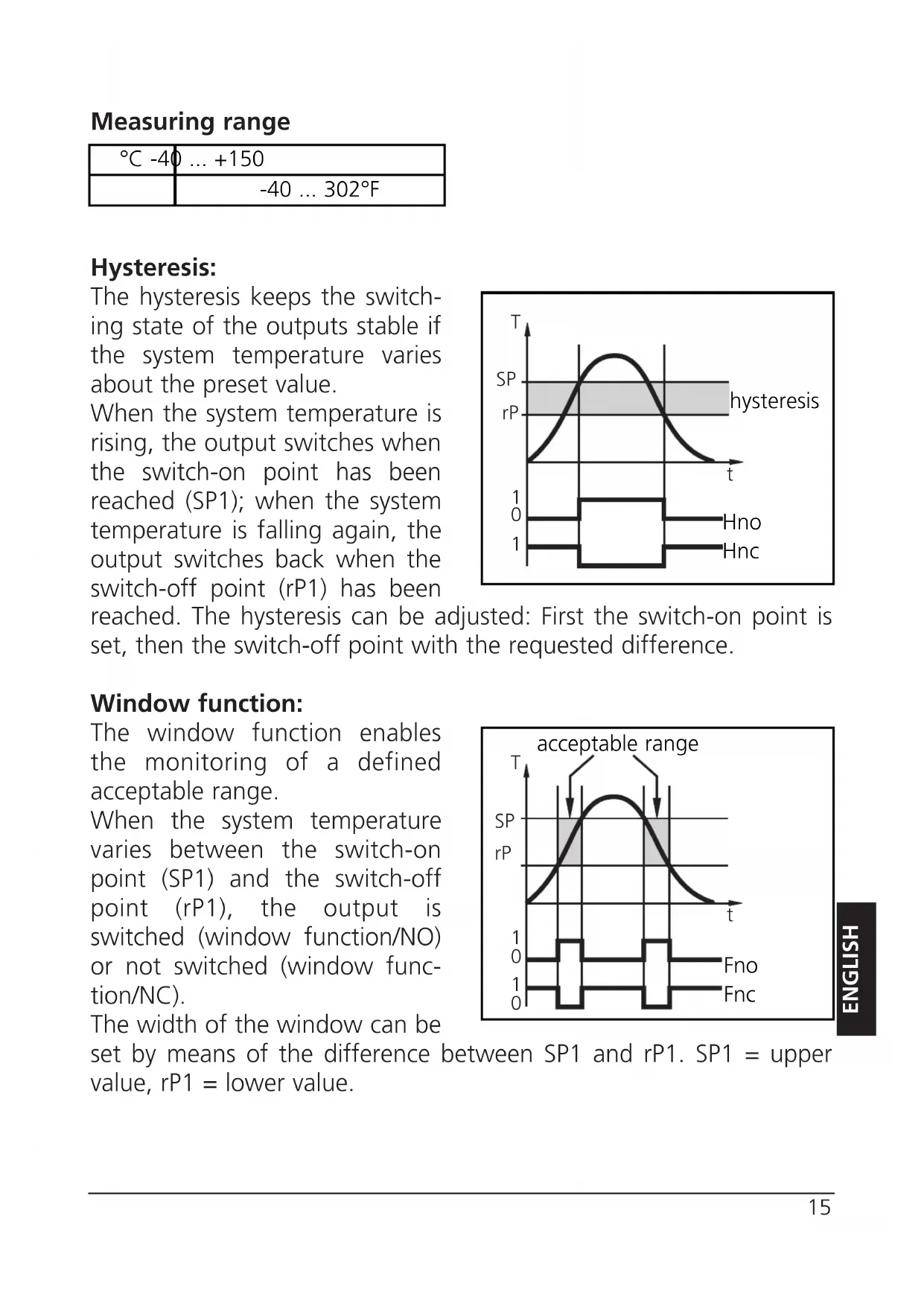
Measuring range
| °C -40 ... +150 | |
| -40 ... 302°F | |
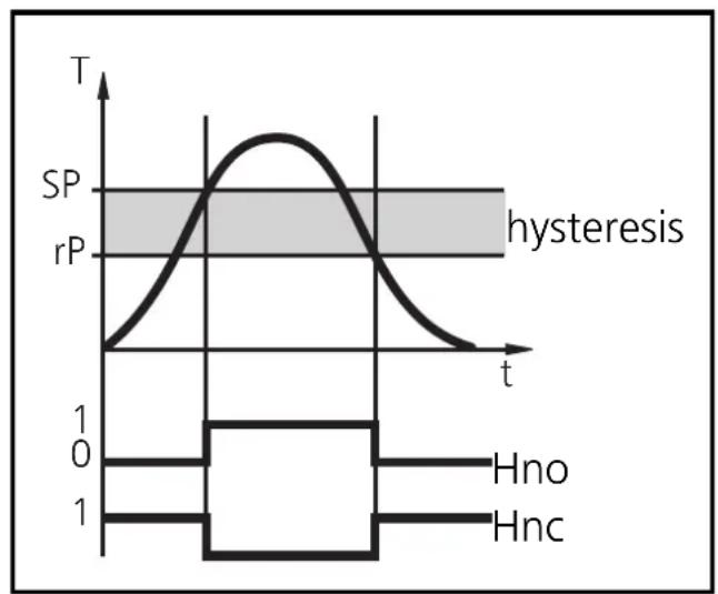
Hysteresis:
The hysteresis keeps the switching state of the outputs stable if the system temperature varies about the preset value.
When the system temperature is rising, the output switches when the switch-on point has been reached (SP1); when the system temperature is falling again, the output switches back when the switch-off point (rP1) has been
reached. The hysteresis can be adjusted: First the switch-on point is set, then the switch-off point with the requested difference.
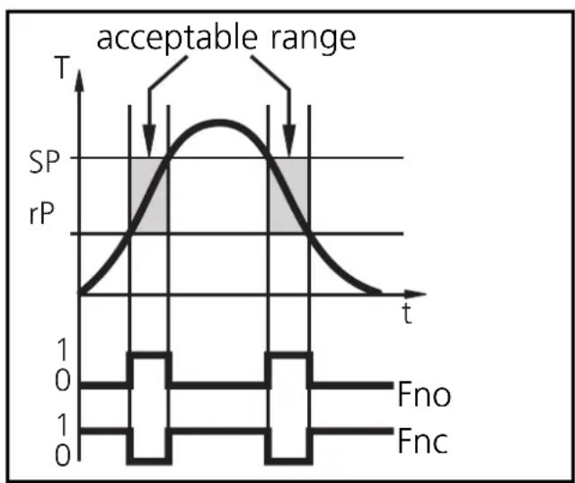
Window function:
The window function enables the monitoring of a defined acceptable range.
When the system temperature varies between the switch-on point (SP1) and the switch-off point (rP1), the output is switched (window function/NO) or not switched (window function/NC).
The width of the window can be
set by means of the difference between SP1 and rP1. SP1 = upper value, rP1 = lower value.
3. Operating modes
Run mode:
(Normal operating mode)
When the supply voltage has been applied, the unit is in the Run mode. It monitors and switches the transistor output according to the set parameters.
The value of the analog output depends on the system temperature. The LED display indicates the current system temperature, the red LED indicates the switching state of the transistor output.
Display mode:
(Indication of parameters and the set parameter values)
When the "Mode/Enter" button is pressed briefly, the unit passes to the Display mode which allows parameter values to be read. The internal sensing, processing and output functions of the unit continue as if in Run mode.
- The parameter names are scrolled with each pressing of the "Mode/Enter" button.
- When the "Set" button is pressed briefly, the corresponding parameter value is displayed for 5 s. After another 5 s the unit returns to the Run mode.
Programming mode:
(Setting of the parameter values)
The unit passes to the programming mode when after the selection of a parameter value (Display mode) the "Set" button is pressed until the display of the parameter value is changed. Internally the unit remains in the operating mode. It continues its monitoring function with the existing parameters until the change has been terminated.
You can change the parameter value by pressing the "Set" button and confirm it by pressing the "Mode/Enter" button. The unit returns to the Run mode when no button has been pressed for 5 s.
4. Adjustable parameters
menu sstructure: see page 3
| SP1 | Switch-on point: Upper limit value at which the output changes its switching status. | ||
| setting range in steps of | |||
| °C | -39.5 ... +150 0.5 | ||
| -39 ... +302 1°F | |||
| -RP1 | Switch-off point: Lower limit value at which the output changes its switching status. | ||
| setting range in steps of | |||
| °C | -40 ... +149.5 0.5 | ||
| -40 ... +301 1°F | |||
| rP1 is always lower than SP1. The unit only accepts values which are lower than SP1.Changing the switch-on point also changes the switch-off point (the hysteresis remains constant).If the hysteresis is higher than the new switch point, it is automatically reduced (rP1 is set to the minimum setting value). | |||
| OU1 | Configuration of the switching output4 switching functions can be set:Hno = hysteresis / normally openHnc = hysteresis / normally closedFno = window function / normally openFnc = window function / normally closed | ||
| ASP | Lower end of analog outputMeasured value for which the output signal is 4 mA / 0 V. | ||
| setting range in steps of | |||
| °C | -40 ... +140 0.5 | ||
| -40 ... +284 1°F | |||
| AEP | Upper end of analog outputMeasured value for which the output signal is 20 mA / 10 V. | ||
| setting range in steps of | |||
| °C | -30 ... +150 0.5 | ||
| -22 ... +302 1°F | |||
| Minimum distance between ASP and AEP = 10°C / 18°F | |||
| AOU | Output function for the analog output 2 options can be selected: I = 4 ... 20 mA / U = 0 ... 10 V | ||
| di5 | Setting of the display 4 options can be selected: °C = display in °Celsius °F = display in °Fahrenheit r°C = display in °Celsius (inverted) r°F = display in °Fahrenheit (inverted) Select the display unit before setting the switch points (SP1, rP1) and the limits for the analog output signal (ASP, AEP). This avoids rounding errors generated internally during the conversion of the units and enables exact setting of the values. Units are delivered from the factory with dis = °C | ||
| CAL | Calibration offset The internal measured value (operating value of the sensor) is offset against the real measured value. | ||
| setting range in steps of | |||
| °C | -9.9 ... +9.9 0.1 | ||
| -17.5 ... +17.5 0.5°F | |||
| Hi Lo | Min-Max memory for system temperature • Hi: displays the highest measured temperature • Lo: displays the lowest measured temperature Erase the memory: - Press the "Mode/Enter" button until HI or Lo is displayed. - Press the "Set" button and keep it pressed until "-" is displayed. - Then press the "Mode/Enter" button briefly. It is recommended to erase the memory as soon as the unit starts working under normal operating conditions. | ||
5. Installation
Connect a temperature sensor to the unit and fix it to the process connection.
6. Electrical connection
The unit must only be connected by an electrician.
The national and international regulations for the installation of electrical equipment must be observed.
Voltage supply to EN50178, SELV, PELV.
Disconnect power before connecting the unit.
Wiring:
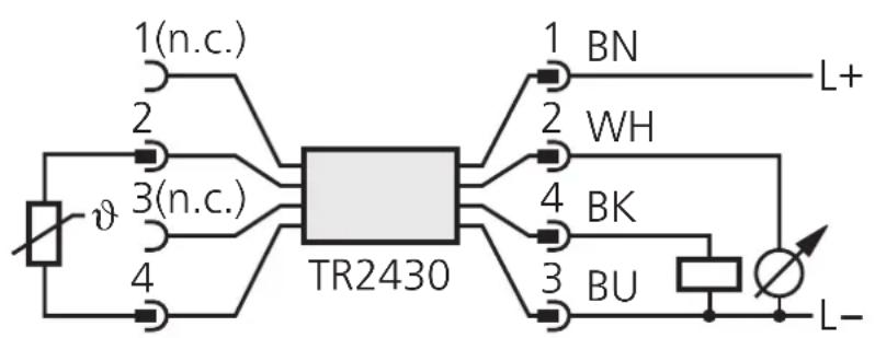
Core colours of ifm sockets:
1 = BN (brown), 2 = WH (white)
3 = BU (blue), 4 = BK (black)
n.c. = not connected
7. Programming
| 1 | Mode/Enter Set | →SP1 | Press the Mode/Enter button several times until the respective parameter is displayed. |
| 2 | Mode/Enter Set | →70 | Press the Set button and keep it pressed. The current parameter value is indicated for 5 s, then the value is increased* (incremental by pressing briefly or scrolling by holding pressed). |
| →100 | |||
| 3 | Mode/Enter Set | →5P1 | Press the Mode/Enter button briefly (= acknowledgement). The parameter is displayed again, the set parameter value becomes effective. |
| Wait 5 s (the unit passes to the operating mode and the current measured value is indicated again), or start again with step 1 to program other parameters. | |||
*Decrease the value: Let the display of the parameter value move to the maximum setting value. Then the cycle starts again at the minimum setting value.
Locking / unlocking:
The unit can be electronically locked to prevent unwanted adjustment of the set parameters: Press (in Run mode) both pushbuttons for 10 s. As soon as the indication goes out the unit is locked or unlocked. Units are delivered from the factory in the unlocked state.
8. Installation and set-up / operation
Check the safe functioning of the unit. The operation is maintenance-free. Failure indication:
| OL | = too high a temperature |
| UL | = too low a temperature |
| SC 1 | (FLASHING) = short-circuit in the switching output; the output is switched off. |
Failure indication (cont.):
| Err | (FLASHING) = no temperature sensor connected, fault or short circuit in the temperature sensor, wire break, evaluable range |
- Technical data
| Operating voltage [V] | 20 ... 30 DC |
| Current rating [mA]. | 250 |
| Short-circuit protection, Reverse polarity protection / overload protection, Integrated Watchdog | |
| Voltage drop [V]. | < 2 |
| Current consumption [mA] | < 66 |
| Constant current [μA] | 385 via the Pt 1000 element |
| Accuracy | |
| Switching output [°C/°F] | ± 0.2 / ± 0.36 |
| Analog output [°C/°F] | ± (0.2 / 0.36 + 0.4% of the set measuring span) |
| Display [°C/°F] | ± (0.2 / 0.36 + 1/2 digit) |
| Resolution | |
| Switching output [°C/°F] | 0.5 / 1 |
| Analog output [°C/°F] | 0.125 / 0.23 |
| Display [°C/°F] | 0.5 / 0.5 |
| Temperature drift [% of value of measuring range/10 K] | ± 0.1 |
| Measuring / display cycle [ms] | 200 |
| Power-on delay time [s] | 1.5 |
| Housing material | stainless steel (304S15); EPDM/X (Santoprene); PC copolymere; Pocan; FPM (Viton) |
| Operating temperature [°C] | -25 ... +70 |
| Storage temperature [°C] | -40 ... +85 |
| Protection | IP 67, III |
| Insulation resistance [MΩ] | > 100 (500 V DC) |
| Shock resistance [g] | 50 (DIN / IEC 68-2-27, 11ms) |
| Vibration resistance [g] | 20 (DIN / IEC 68-2-6, 10 - 2000 Hz) |
| EMC | |
| IEC 1000/4/2 ESD: | 4 / 8 KV |
| IEC 1000/4/3 HF radiated: | 10 V/m |
| IEC 1000/4/4 Burst: | 2 KV |
| IEC 1000/4/6 HF conducted: | 10 V |
- Programmieren / Programming / Programmation
- Controls and visual indication
- Functions and features
- Measuring range
- Hysteresis:
- Window function:
- Operating modes
- Run mode:
- Display mode:
- Programming mode:
- Adjustable parameters
- Installation
- Electrical connection
- Programming
- Locking / unlocking:
- Installation and set-up / operation
Brand : IFM
Model : TR2430
Category : Temperature sensor amplifier