
FFI7300WL - Fridge VIKING - Free user manual and instructions
Find the device manual for free FFI7300WL VIKING in PDF.

| Product Type | Assembly Kit for Series 7 Refrigerators |
| Brand | Viking |
| Model | FFI7300WL |
| Category | Refrigerator |
| Opening dimensions (width) | Variable based on combination (from 36 in. to 72 in.) |
| Opening height | 84 in. (213.4 cm) min. / 85-3/16 in. (216.3 cm) max. |
| Opening depth | 25 in. (63.5 cm) |
| Items supplied | Heater, center rod brackets, center rod, tie plate (top and rear), fasteners |
| Required tools | Drill, drill bits, hex sockets, rubber mallet, 3/8 in. wrench, 1/8 in. Allen key |
| Anti-tip system | Bracket with 12 holes, at least 4 fasteners required |
| Number of people for installation | 2 or more persons |
| Power supply | 120 V, 60 Hz (estimated) |
| Heating function | Anti-condensation, activated via control panel |
| Compatibility | Series 7 refrigeration appliances |
| Foot adjustment | Leveling feet, 4 turns at a time with hand ratchet |
| Combination options | Widths of 18 in., 24 in., 30 in., 36 in. |
Frequently Asked Questions - FFI7300WL VIKING
User questions about FFI7300WL VIKING
0 question about this device. Answer the ones you know or ask your own.
Ask a new question about this device
Download the instructions for your Fridge in PDF format for free! Find your manual FFI7300WL - VIKING and take your electronic device back in hand. On this page are published all the documents necessary for the use of your device. FFI7300WL by VIKING.
USER MANUAL FFI7300WL VIKING
Multi-Unit Refrigeration Connector Kit
CKVBI
Table of Contents
NOTE: These instructions include information on how to install multiple 7 Series refrigeration units. For information on dimensions, specifications, and installation of single units, please refer to the installation guide included with the appliances.
Parts Included 2
Tools Needed 2
Cutout dimensions 3
Specifications 4
Anti-tip location 7
Preparing Units for Installation 8
Installation 10
WARNING
TIP OVER HAZARD

Appliance is top heavy and tips easily when not completely installed. Keep doors closed until appliance is completely installed and secured per installation instructions.
Use two or more people to move and install appliance. Failure to do so can result in death or serious injury.
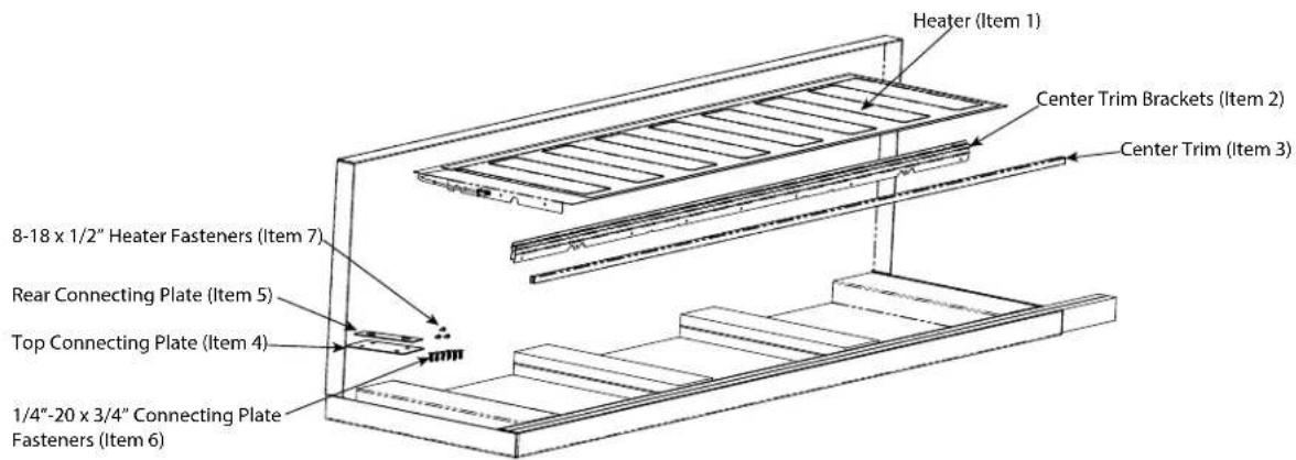
Parts included Tools Needed
Heater (1)
Center Trim Brackets (2)
Center Trim (1)
Top Connecting Plate (1)
Rear Connecting Plate (1)
1/4"-20 x 3/4" Connecting Plate Fasteners (6)
8-18 x 1/2" Heater Fasteners (3)
Drill (Not to be used on the leveling feet)
Drill Bits - 3" Phillips (PH2), Torx (T15 & T20)
1/4" & 5/16" Hex Drive
Rubber Mallet
3/8" Wrench
1/8" Allen Wrench
Cutout Dimensions
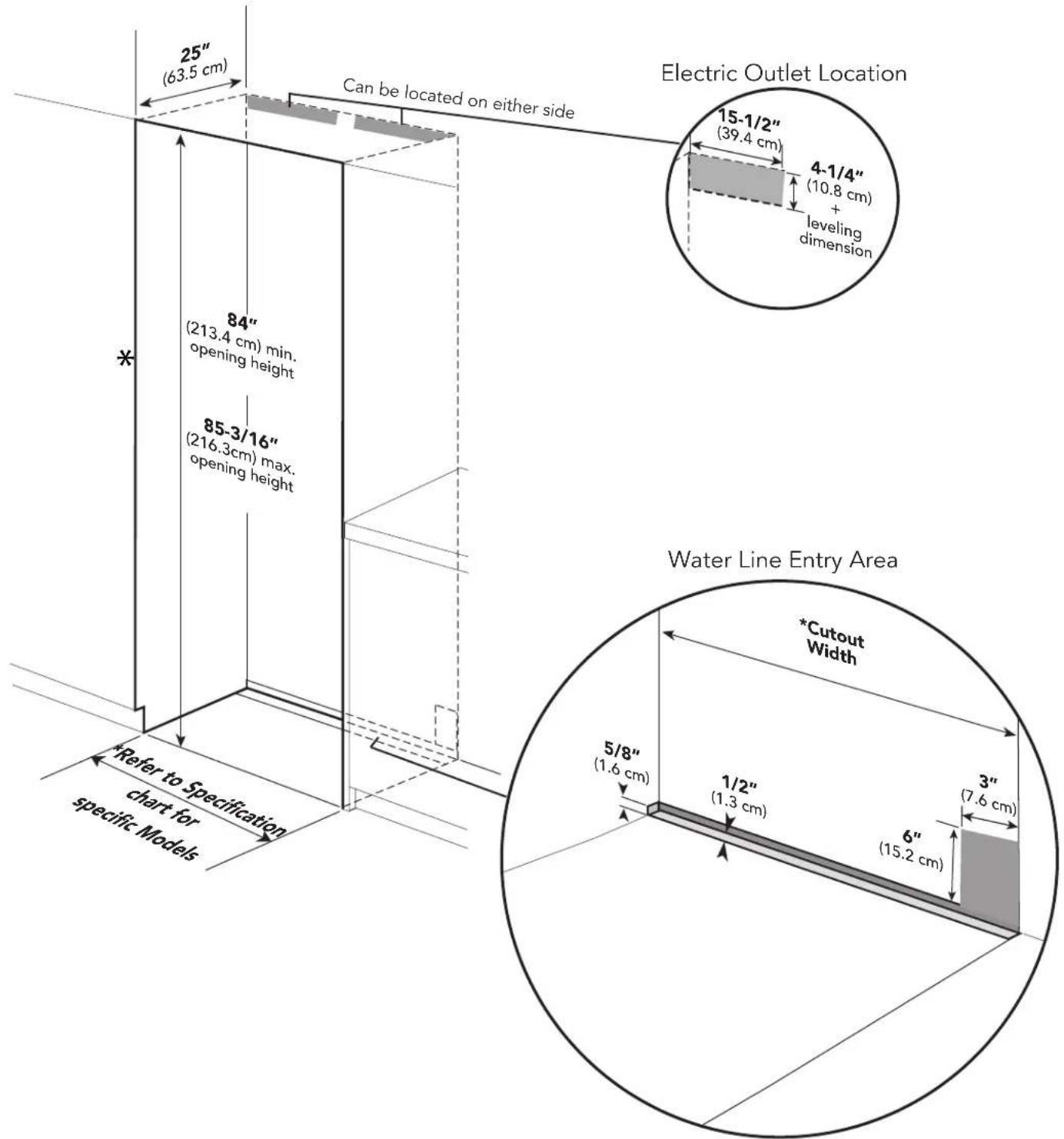
*Note: For all models, 3" back from the front of the cabinet on both sides needs to be finished like the outside of the cabinets
Specifications
Refer to Installation Guides included with unit for individual dimensions.
Below is a common install chart for reference.
| Size Combination Cabinet Cutout Width | Cabinet Cutout Height (same for all) | Cabinet Cutout Depth (same for all) | Optional Kickplate | |
| 18" W / 24"W Models | 42" (106.7 cm) | 84" (213.4 cm) min 85-3/16" (216.3 cm) max | 25" (63.5 cm) | TKK742SS |
| 18" W / 30"W Models | 48" (121.9 cm) TKK748SS | |||
| 18" W / 36"W Models | 54" (137.2 cm) TKK754SS | |||
| 24" W / 24"W Models | 48" (121.9 cm) TKK748SS | |||
| 24" W / 30"W Models | 54" (137.2 cm)" TKK754SS | |||
| 24" W / 36"W Models | 60" (152.4 cm) TKK760SS | |||
| 30" W / 30"W Models | 60" (152.4 cm) TKK760SS | |||
| 30" W / 36"W Models | 66" (167.6 cm) TKK766SS | |||
| 36" W / 36"W Models | 72" (182.9 cm) TKK772SS | |||
For muti-unit installation, add the width of the units together for cabinet cutout width.
For example: 18'' + 24'' + 24'' = 66'' W.
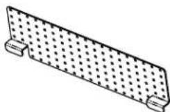
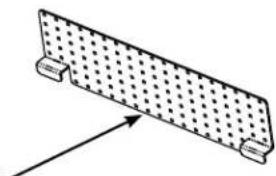
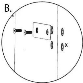
Anti-tip Location
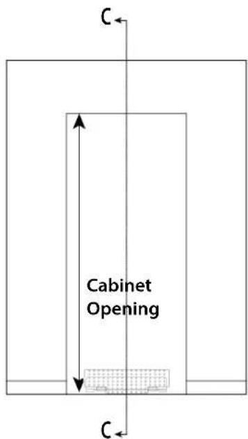
Anti-tip Bracket
natural_image
Simple line drawing of a rectangular plate with a grid pattern and two side supports (no text or symbols)The anti-tip bracket has several holes set up on a grid in order to better locate a wall stud. At least 4 places must be used. Anti-tip Bracket must be centered in cutout - side to side.
NOTE: Number and type of fasteners must be suitable in order to prevent tipping. For example: use wood screws into wall studs or masonry anchors if attaching to stone, brick or concrete.
If a wall stud can not be found or when installing the 18" model, use the lower section of the bracket and mount to the base board
natural_image
Simple line drawing of a rectangular plate with a dotted pattern and two side supports, no text or symbols present.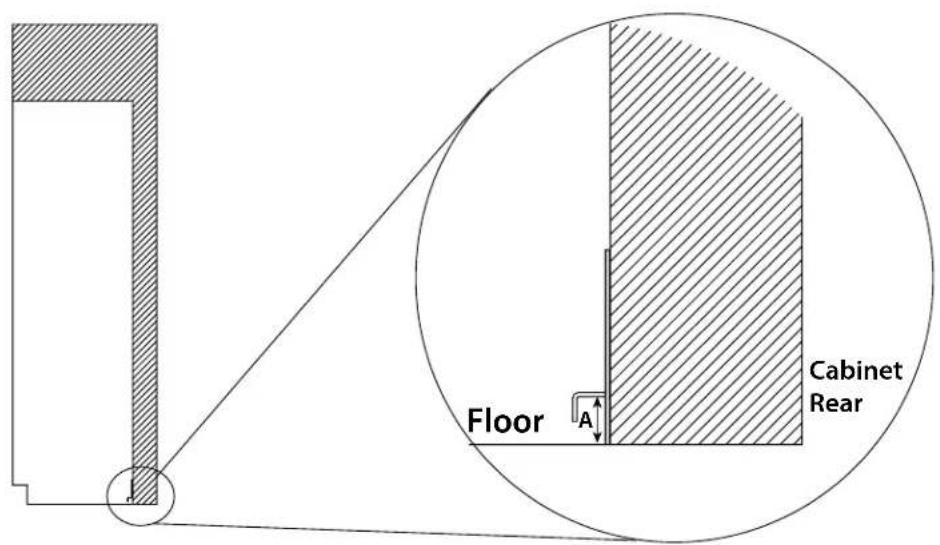
Dimension A = Cabinet opening minus the refrigerator height + 1-1/4" (3.2 cm)
Ex. - Cabinet opening height - 85"
Minimum refrigerator height (sitting on rollers) - 83 15/16"
$$ A = 8 5 ^ {\prime \prime} - 8 3 - 1 5 / 1 6 ^ {\prime \prime} + 1 - 1 / 4 ^ {\prime \prime} = 2 - 5 / 1 6 ^ {\prime \prime} $$
Preparing Units for Installation
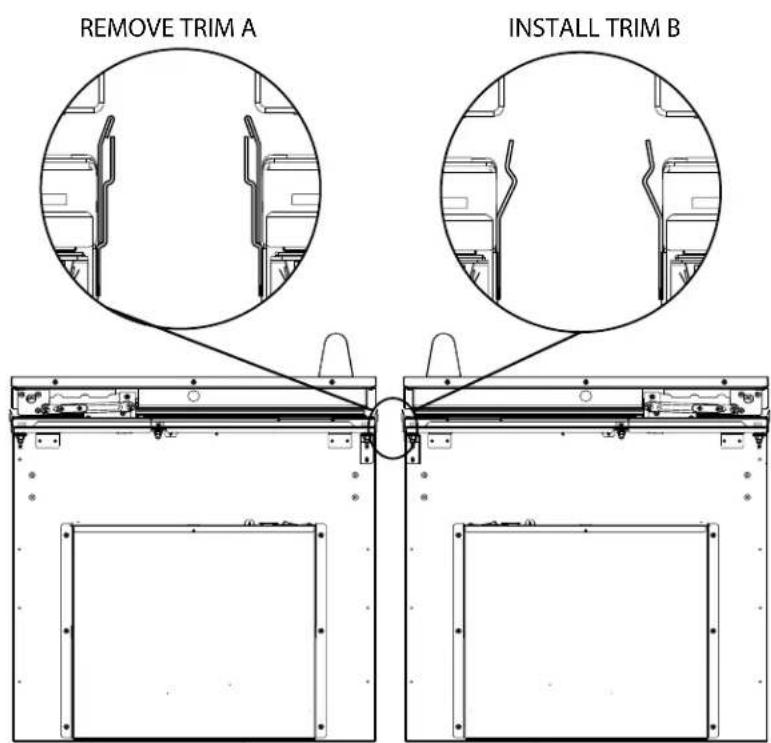
Before removing units from pallet, remove the side trim from each unit, install center trim brackets and connection heater (steps 1 thru 4). Make sure units are unplugged and powered off.
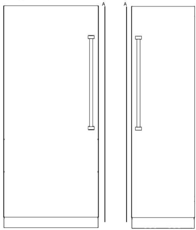
natural_image
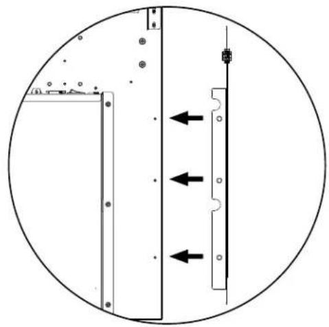
Two simple rectangular panels with vertical supports, labeled 'A', no text or symbols present.Look closely at the trim already installed on the unit. If the trim resembles that in Trim A, it will need to be removed and replaced with Trim B. If the trim already resembles Trim B, leave as is.
Preparing Units for Installation
- Fasten heater (Item #1) to the three mounting holes on top of the right hand unit using the #8-18 x 1/2" fasteners (Item #7) provided.
natural_image
Pure diagram of a mechanical or electrical component with directional arrows, no text or symbols present
natural_image
Technical line drawing of a mechanical or electrical component with three parallel channels and mounting brackets (no text or symbols)- Plug heater terminal into right hand unit using the plug located next to the unit on/off switch.
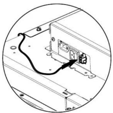
natural_image
Diagram of an electrical outlet with a cable inserted into a wall-mounted switch (no text or symbols visible)WARNING

TIP OVER HAZARD
Appliance is top heavy and tips easily when not completely installed. Keep doors closed until appliance is completely installed and secured per installation instructions.
Use two or more people to move and install appliance. Failure to do so can result in death or serious injury.
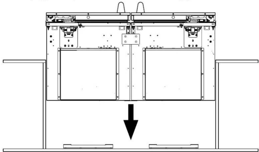
- Remove units from pallets and position together outside of the cabinet so that top connecting plate (Item #4) can be installed. If installing on uneven surfaces, use unit leveling feet to adjust units to that they are at the same height.
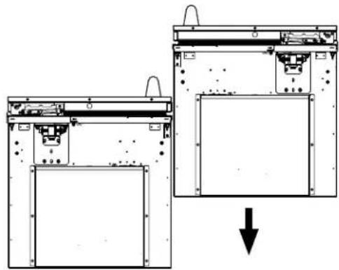
natural_image
Diagram showing two views of a device with internal components and a downward arrow indicating a process (no text or symbols present)- Install top connecting plate to the threaded mounting holes provided on the top of the cabinet using the 1/4"-20 x 3/4" (Item #6) fasteners. DO NOT install using a drill. Use manual allen wrench. (See Illustration A)

natural_image
Technical diagram of a mechanical assembly with mounting holes and structural supports (no text or labels)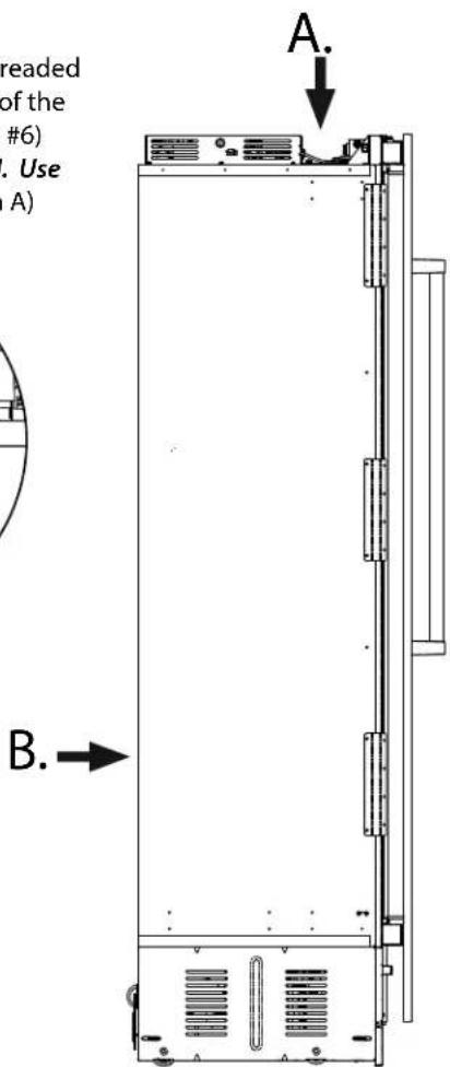
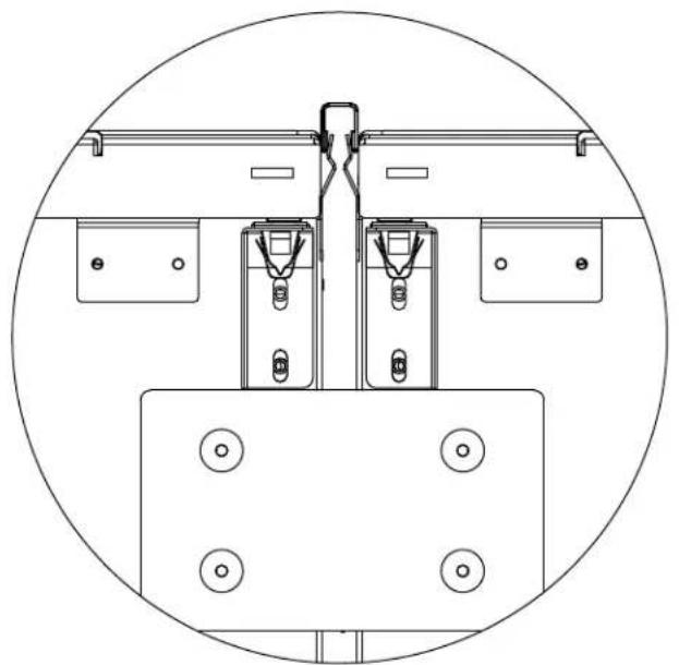
- Fasten rear connecting plate (Item #5) to the threaded mounting holes provided on the rear of the unit using the 1/4"-20 x 3/4" (Item #6) fasteners. DO NOT install using a drill. Use manual allen wrench. (See Illustration B). Loosely attach the bracket allowing it to pivot. Tightening the screws will result in the bracket bending and causing misalignment of the rear of the units.
Note: *If one or both units have (4) screw holes, attach using the top two holes.
natural_image
Simple diagram of a mechanical or electrical component inside a circular boundary, with no visible text, numbers, or symbols.Installation
- If unit leveling feet were used, lower units back onto rollers. Plug in electrical supply and roll connected units into cabinet cutout. Units must be plugged into separate electric outlets. Connect water supply to each unit.
natural_image
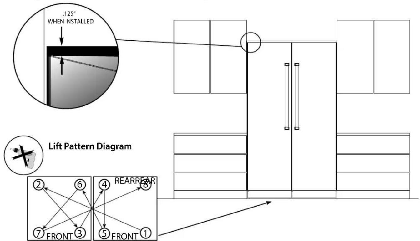
Technical line drawing of a mechanical device with internal components and a downward arrow indicating motion (no text or symbols)- Lift units to desired height using 5/16" socket and hand ratchet. DO NOT USE A DRILL-(refer to lift pattern diagram below to ensure that units are gradually lifted together.) **IMPORTANT** - Only make 4 turns at a time with the hand ratchet**. Attach units to cabinet side trim and fasteners included with the units. Install stainless magnetic side trim once fastened. (Use installation guide included with individual units as a reference.)
Installation
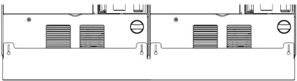
- Remove plastic film from center trim before installing. Install center connecting trim (Item #3) in between the two units by pressing it in. Trim should be even with the top of the units. If needed, tap connecting trim gently into place with rubber mallet.
natural_image
Technical line drawing of a mechanical assembly with mounting brackets and mounting holes (no text or symbols)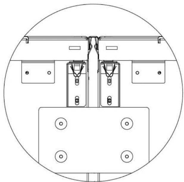
natural_image
Technical line drawing of a mechanical assembly with mounting brackets and mounting holes (no text or symbols)NOTE: Open both doors to install the trim. When installed, the face of the trim should be flush with the breaker frame.
- Once the connection to the heater and the unit installation is complete, you will need to enable the heater which was plugged into the right hand unit. (Step 4 on page 7).
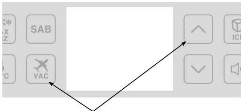
flowchart
graph TD
    A["SAB"] --> B["VAC"]
    C["ICU"] --> B
    D["OK"] --> B
To enable the heater, on the control panel* of the right hand unit, press the VAC and UP arrow key and hold for 5 seconds. You will hear an alarm beep once when it accepts the entry.
*NOTE: Control panel may vary depending on model being installed.
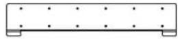
Optional Custom Kickplate Installation
Remove screws fastening individual kickplates on units. Save screws to be used when installing custom kickplate. Place custom kickplate across bottom of both units and fasten using the mounting holes for the individual kickplates.
natural_image
Technical line drawing of a mechanical or electrical component with multiple vertical supports and mounting holes (no text or symbols)Viking Range, LLC
111 Front Street
Greenwood, Mississippi 38930
(662) 455-1200
For product information, call 1-888-845-4641
or visit our web site at vikingrange.com
Guide
d'installation
SÉRIE 7
Support anti-basculement
natural_image
Pure architectural line drawing of two doors with vertical supports, no text or symbols presentnatural_image
Pure diagram of a mechanical or electrical component with directional arrows, no text or symbols present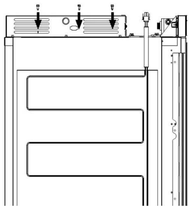
natural_image
Technical line drawing of a mechanical or electrical component with three parallel channels and mounting brackets (no text or symbols)natural_image
Diagram of an electrical outlet with a cable inserted into a wall-mounted switch (no text or symbols visible)
AVERTISSEMENT
RISQUE DE BASCULEMENT

natural_image
Diagram showing two views of a printer or printer device with internal components and a downward arrow indicating process (no text or symbols present)natural_image
Technical diagram of a mechanical assembly with mounting brackets and bolts, no visible text or symbols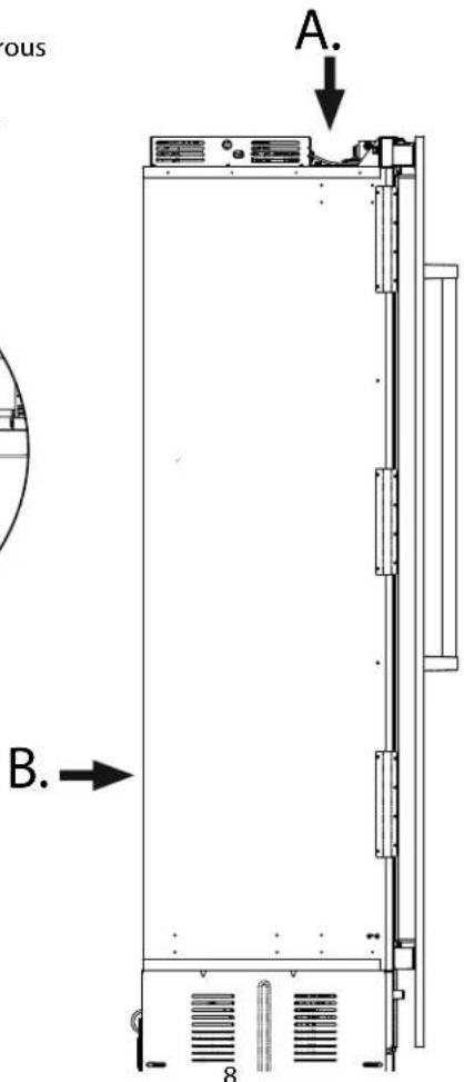
natural_image
Simple line drawing of a mechanical component inside a circular frame, with no text or symbols present.Installation
natural_image
Technical line drawings of mechanical components, showing front and side views with mounting holes and mounting brackets (no text or symbols)natural_image
Technical line drawing of a mechanical or electrical component with multiple vertical supports and mounting holes (no text or symbols)Viking Range, LLC
111 Front Street
Greenwood, Mississippi 38930 É.-U.
(662) 455-1200

Brand : VIKING
Model : FFI7300WL
Category : Fridge