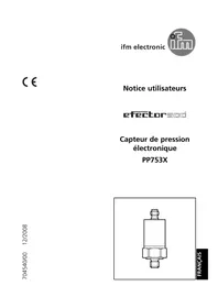
PP7533 - Pressure sensor IFM - Free user manual and instructions
Find the device manual for free PP7533 IFM in PDF.


User questions about PP7533 IFM
0 question about this device. Answer the ones you know or ask your own.
Ask a new question about this device
Download the instructions for your Pressure sensor in PDF format for free! Find your manual PP7533 - IFM and take your electronic device back in hand. On this page are published all the documents necessary for the use of your device. PP7533 by IFM.
USER MANUAL PP7533 IFM
Operating instructions
Electronic pressure sensor
PP75xx
Contents
1 Preliminary note.... 3
1.1 Symbols used.... 3
1.2 Warnings.... 3
2 Safety instructions 4
2.1 Cybersecurity 4
3 Transport, handling and storage 6
4 Intended use 7
4.1 Application area 7
5 Function 8
5.1 Communication, parameter setting, evaluation 8
5.2 IO-Link 8
5.3 Operating modes 8
5.4 Switching function 9
5.5 Teach function 10
5.6 Zero point behaviour of the device display and the outputs.... 10
6 Installation.... 12
7 Electrical connection 13
8 Parameter setting.... 14
8.1 List of the parameters.... 14
8.2 Menu structure / display in PP2001 15
8.3 Parameter setting in general.... 16
8.3.1 Open menu level 2.... 16
8.4 Setting for operating mode 1 (2 switching outputs).... 16
8.4.1 Setting of the output function.... 16
8.4.2 Set switching limits.... 16
8.5 Setting for operating mode 2 (switching output + teach input).... 16
8.5.1 Configuring pin 4 as teach input.... 16
8.5.2 Defining the output function for the switching output.... 17
8.5.3 Setting of the hysteresis / width of the window 17
8.6 Setting for operating mode 3 (switching output + diagnostic output) 17
8.6.1 Setting of the output function for OUT1 17
8.6.2 Set switching limits.... 17
8.6.3 Setting of OUT2 as diagnostic output 17
8.7 Communication mode 17
8.8 User settings (optional) 18
8.8.1 Setting the unit of measurement for the system pressure.... 18
8.8.2 Setting of the update rate for the display 18
8.8.3 Setting the switch-on delay 18
8.8.4 Setting the damping of the measured value 18
8.9 Service functions.... 19
8.9.1 Reading the min/max values for the system pressure.... 19
8.9.2 Read error number.... 19
8.9.3 Reset all parameters to factory setting.... 19
8.10 Teaching switch point SP2 19
8.10.1 Teaching with PP2001 19
8.10.2 Teaching by input signal on PIN 4.... 20
9 Operation.... 21
9.1 LED operation indicators 21
9.2 Error indications 21
10 Disposal, repair and return 22
11 Factory setting.... 23
1 Preliminary note
You will find instructions, technical data, approvals and further information using the QR code on the unit / packaging or at documentation.ifm.com.
1.1 Symbols used
Requirement
Instruction
Reaction, result
bold Designation of keys, buttons or indications
→ Cross-reference without link
→ Cross-reference with link


1.2 Warnings
Warnings indicate the possibility of personal injury and damage to property. This enables safe product handling. Warnings are graded as follows:

WARNING
Warning of serious personal injury
▷ If the warning is not observed, fatal and serious injuries are possible.

CAUTION
Warning of minor to moderate personal injury
▷ If the warning is not observed, minor to moderate injuries are possible.

ATTENTION
Warning of damage to property
▷ If the warning is not observed, damage to property is possible.
2 Safety instructions
- The unit described is a subcomponent for integration into a system.
- The system architect is responsible for the safety of the system.
-
The system architect undertakes to perform a risk assessment and to create documentation in accordance with legal and normative requirements to be provided to the operator and user of the system. This documentation must contain all necessary information and safety instructions for the operator, the user and, if applicable, for any service personnel authorised by the architect of the system.
-
Read this document before setting up the product and keep it during the entire service life.
- The product must be suitable for the corresponding applications and environmental conditions without any restrictions.
- Only use the product for its intended purpose (→ Intended use).
- If the operating instructions or the technical data are not adhered to, personal injury and/or damage to property may occur.
- The manufacturer assumes no liability or warranty for any consequences caused by tampering with the product or incorrect use by the operator.
- Installation, electrical connection, set-up, operation and maintenance of the product must be carried out by qualified personnel authorised by the machine operator.
- Protect units and cables against damage.
- Only use the product for permissible media (→ Technical data).
- Use in gases at pressures >2,5 MPa (>25 bar) only on request.

CAUTION
With high medium temperatures, parts of the device may heat up.
▷ Risk of burns
▶ Do not touch the device.
▶ Protect the housing against contact with flammable substances and unintentional contact.
- High-pressure devices (400 bar) are equipped with a pressure relief mechanism and an integrated damping device to avoid any risk of injury in case of bursting when the bursting pressure is exceeded, and to comply with the regulations for UL approval.

CAUTION
Any manipulation of the damping device is not permissible.
For devices with cULus approval this approval becomes invalid when the damping device is removed.
When the damping device is removed, there is no damping function any more.
▷ Risk of injury!
2.1 Cybersecurity
Installation
The device is suitable for operation in a secure environment according to IEC 62443-1-1.
The device was designed for operation behind a firewall.
▶ Carry out a risk assessment of the system according to IEC 62443-1-1.
▶ Take measures to ensure physical security.
Operation
▶ Observe the security functions described in the product documentation and the recommendations for their use.
Maintenance
- ▶ Back up system configuration and system data in accordance with your company’s change management processes.
Decommissioning
▶ Ensure that no sensitive information can fall into unauthorised hands.
▶ Always reset the system settings to the factory settings before decommissioning the device.
3 Transport, handling and storage
▶ Store the device in its original packaging.
▶ Observe the permissible ambient conditions for the device during storage (→ Technical data).
▶ When the device is to be stored again, use the original packaging.
▶ Otherwise, provide unused connections with either a mating connector or a protective cap and pack the device in suitable packaging.
4 Intended use
The unit monitors the system pressure in a plant.
4.1 Application area
Type of pressure: relative pressure
The device is suited for use in mobile vehicles.

The units are vacuum resistant.

Information on pressure rating and bursting pressure ➕ Data sheet

Pressure Equipment Directive (PED):
The devices with a final value of the measuring range of ≤ 1000 bar comply with the Pressure Equipment Directive and are designed and manufactured for group 2 fluids in accordance with sound engineering practice.
Use of media from group 1 fluids on request.

If the cable length exceeds 30 m or if used outside buildings, there is a risk of overvoltage pulses from external sources. We recommend to use the unit in protected operating environments and to limit overvoltage pulses to max. 500 V.

CAUTION
Static and dynamic overpressure
▷ Destruction of the device even if the indicated bursting pressure is exceeded only for a short time. Risk of injury!
▶ Make sure that the pressure rating and bursting pressure specified in the data sheet are not exceeded.
5 Function
5.1 Communication, parameter setting, evaluation
- The device generates output signals according to the parameter setting.
• Moreover, it provides the process data via IO-Link. - The device is designed for fully bidirectional communication. So the following options are possible:
– Remote display: reading and displaying the current system pressure.
– Remote evaluation: transfer of switching signals (only with PP2001).
- Remote parameter setting: reading and changing current parameter settings with PP2001 or via IO-Link.
- Using PP2001, the current parameter setting can be stored and transferred to other devices of the same type.
5.2 IO-Link
IO-Link is a communication system for connecting intelligent sensors and actuators to automation systems. IO-Link is regulated in the IEC 61131-9 standard.

General information about IO-Link can be found at io-link.ifm.

The Input Output Device Description (IODD) with all parameters, process data and detailed descriptions of the device can be found at documentation.ifm.com.
IO-Link offers the following advantages:
- Noise immune transmission of all data and process values
• Parameter setting during operation or default setting outside the application - Parameters to identify the connected devices in the plant
• Additional parameters and diagnostic functions - Logging of parameter sets, process values and events
• Device description file (IODD – Input Output Device Description) for easy configuration
• Standardised electrical connection - Remote maintenance
5.3 Operating modes
1: Pressure sensor with 2 switching outputs
2 limit values for pressure can be monitored. Pin 4 = output 1, pin 2 = output 2.
2: Pressure sensor with one switching output and one teach input
One threshold for pressure can be monitored. The current system pressure can be set as threshold at any time by the teach signal. Pin 4 = input for teach signal, pin 2 = switching output.
3: Pressure sensor with one switching output and one diagnostic output.
One threshold for pressure can be monitored. In addition, a fault signal is provided on output 2: in case of a fault, output 2 is inactive. Pin 4 = switching output, pin 2 = output for diagnostic signal.
4: Communication mode
There are 2 options for bidirectional communication:
- Communication with the handheld programming device PP2001.
- Communication with a PC or controller via IO-Link.
For communication mode, no parameter setting is necessary. Using pin 4 (data channel), data can be entered or read at any time.

Voltage supply for the communication mode: 18...32 V
5.4 Switching function
OUTx changes its switching status if it is above or below the set switching limits (SPx, rPx). The following switching functions can be selected:
- Hysteresis function / normally open: OU1 / OU2 = Hno (→ Figure hysteresis function).
-
Hysteresis function / normally closed: OU1 / OU2 = Hnc (→ Figure hysteresis function).
▶ First the set point (SPx) is set, then the reset point (rPx).
▷ The hysteresis defined remains even if SPx is changed again. -
Window function / normally open: OU1 / OU2 = Fno (→ Figure window function).
- Window function / normally closed: OU1 / OU2 = Fnc (→ Figure window function).
- The width of the window can be set by means of the difference between FHx and FLx. FHx = upper value, FLx = lower value.
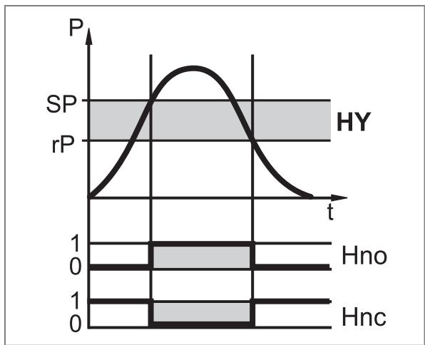
Fig. 1: Hysteresis function

Fig. 2: Window function
| P = | System pressure |
| HY = | Hysteresis |
| FE = | Window |
5.5 Teach function
Teach for hysteresis function:
During the teach operation, the current system pressure is taken as set point. The set hysteresis remains constant: SP2 = system pressure, rP2 = system pressure minus hysteresis.
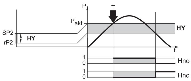
P: System pressure
Pakt: Current system pressure
HY: Hysteresis
T: Time of teach
Teach for window function:
During the teach operation the window is set so that the current system pressure is in the middle of the window: SP2 = system pressure plus 1/2 window width; rP2 = system pressure minus 1/2 window width.

P: System pressure
Pakt: Current system pressure
FE: Window
T: Time of teach
5.6 Zero point behaviour of the device display and the outputs

Due to permissible device tolerances and temperature changes, the sensor can show a deviation from the zero point when no pressure is applied. To prevent this, the device is equipped with functions that keep the measured signal more stable at the process value 0.
Zero point behaviour of the device display, the switching output and the IO-Link communication:

Fig. 3: device display, switching output and communication via IO-Link
1: Process value
2: Sensor output signal with hysteresis (green)
3: Ideal measurement signal (red)
4: System pressure
5: Zero point stabilisation → Data sheet
The first process value displayed on the device display that can be evaluated via the switching output or IO-Link communication is determined by the zero point stabilisation.

The zero point stabilisation is indicated in % of the span ➕ Data sheet.
6 Installation

CAUTION
Escaping compressed air or hot media.
▷ Risk of injury caused by pressure or burns.
▶ Before installing or removing the device, ensure that no pressure is applied to the system and that there is no medium in the pipe or tank.
▶ Note dangers related to machine / medium temperatures.
▶ Insert the device in a process connection G1/4.
▶ Tighten firmly. Recommended tightening torque: 25 Nm (max. 50 Nm).
7 Electrical connection

The unit must be connected by a qualified electrician.
Observe the national and international regulations for the installation of electrical equipment.
Voltage supply according to SELV, PELV.
▶ Disconnect power.
▶ Connect the unit as follows:
Connector: 1 x M12; coding: A


| Pin | Assignment |
| 1 | L+ |
| 2 | OUT2:• pnp switching signal: limit values for pressure• Diagnostic signal. |
| 3 | L- |
| 4 | OUT1:• pnp switching signal: limit values for pressure• input for teach signal• IO-Link communication |
Circuit example and teach mode:


8 Parameter setting

Parameter setting with PP2001: ➕ Operating instructions PP2001.
Parameters can be set before installation or during operation.

If you change parameters during operation, this will influence the function of the plant.
▶ Ensure that there will be no malfunctions in your plant.
During parameter setting the unit remains in the operating mode. It continues to monitor with the existing parameter until the parameter setting has been completed.
The device parameters can be set via the IO-Link interface in the following ways, for example:
- Parameter setting via a suitable parameter setting software, e.g. ifm moneo|configure
• Parameter setting via a PLC
• Parameter setting via an IIoT application
Requirements for parameter setting via the IO-Link interface:
√ The Input Output Device Description (IODD) for the device in case of parameter setting via a parameter setting software, see documentation.ifm.com
√ The IO-Link interface description (PDF) for the device in case of parameter setting via a PLC or IIoT application, see documentation.ifm.com
√ An IO-Link master
▶ Connect the IO-Link master to the parameter setting software, the PLC or the IIoT application.
▶ Connect the device to a suitable free port of the IO-Link master.
▶ Set the port of the IO-Link master to the IO-Link operating mode.
▷ The device changes to the IO-Link mode.
▶ Change the parameter settings in the software.
▶ Write the parameter settings to the device.

Support for system integration and parameter setting via IO-Link:
→ Manual of the parameter setting software (e.g. moneo)
Explanations and startup packages at ifm.com/cnt/io-link-system-integration.
8.1 List of the parameters
| Parameter | Function |
| SP1/rP1 | Upper / lower threshold for system pressure at which OUT1 switches. |
| SP2/rP2 | Upper / lower threshold for system pressure at which OUT2 switches. |
| OU1 | Output function for OUT1:Switching signal for the thresholds: hysteresis function or window function, either normally open or normally closed. Alternatively: configure pin 4 as input for teach signal: OU1 = tch. |
| OU2 | Output function for OUT2:Switching signal for the thresholds: hysteresis function or window function, either normally open or normally closed. Alternatively: configure OUT2 as diagnostic output: OU2 = dESI. |
| EF | Extended functions / opening of menu level 2. |
| Uni | Standard unit of measurement for system pressure. |
| HI | Maximum value memory for system pressure. |
| LO | Minimum value memory for system pressure (only for PP7554). |
| dS1/dS2 | Switch-on delay for OUT1 / OUT2. |
| dr1/dr2 | Switch-off delay for OUT1 / OUT2. |
| dAP | Measured value damping for filtering pressure peaks. |
| diS | Update rate for the measured value display / orientation of the display of PP2001. |
| TSP2 | Triggers the teach function in the connected sensor. |
| Fnr | Error memory (shows the last error that occurred). |
| rES | Restore factory setting. |
8.2 Menu structure / display in PP2001

8.3 Parameter setting in general

For parameter setting with PP2001:
Confirm each entry of a parameter value with Mode / Enter.
8.3.1 Open menu level 2
| With PP2001:► ▶ Select EF.► ▶ Briefly press Set. If menu level 2 is protected by an access code, “Cod1” flashes in the display.► ▶ Press Set and keep it pressed until the valid code no. is displayed.► ▶ Briefly press Mode / Enter. | EF |

Factory setting: no access restriction.
8.4 Setting for operating mode 1 (2 switching outputs)
8.4.1 Setting of the output function
| ▶ Select OU1 / OU2 and set the switching function:Hno = hysteresis function / normally open. Hnc = hysteresis function / normally closed. Fno = window function / normally open. Fnc = window function / normally closed. | OU1OU2 |
8.4.2 Set switching limits
| ▶ Select SP1 / SP2 and set the value at which the output switches. | SP1 |
| SP2 | |
| ▶ Select rP1 / rP2 and set the value at which the output switches. | rP1 |
| rPx is always smaller than SPx. The device only accepts values which are lower than the value for SPx. | rP2 |
8.5 Setting for operating mode 2 (switching output + teach input)
8.5.1 Configuring pin 4 as teach input
| ▶ Select OU1 and set the function tch. | OU1 |
8.5.2 Defining the output function for the switching output
Factory setting: OU2 = Hno = hysteresis function / normally open. If necessary, change the output function as follows:
| ▶ Select OU2 and set the output function:Hno = hysteresis function / normally open Hnc = hysteresis function / normally closed Fno = window function / normally open Fnc = window function / normally closed | OU2 |
8.5.3 Setting of the hysteresis / width of the window
Factory setting: hysteresis / window = 2 % of the final value of the measuring range. If necessary, change it as follows:
| ▶ Select rP2 and set the smallest possible value. | rP2 |
| ▶ Select SP2 and set the following value: rP min plus requested hysteresis / window width. | SP2 |
8.6 Setting for operating mode 3 (switching output + diagnostic output)
8.6.1 Setting of the output function for OUT1
| ▶ Select OU1 and set the output function:Hno = hysteresis function / normally open Hnc = hysteresis function / normally closed Fno = window function / normally open Fnc = window function / normally closed | OU1 |
8.6.2 Set switching limits
| ▶ Select SP1 and set the value at which the output switches. | SP1 |
| ▶ Select rP1 and set the value at which the output is reset. rP1 is always smaller than SP1. The unit only accepts values which are lower than SP1. | rP1 |
8.6.3 Setting of OUT2 as diagnostic output
| ▶ Select OU2 and set the function dESI. | OU2 |
8.7 Communication mode
For communication mode, no parameter setting is necessary. Using pin 4 (data channel), data can be entered or read at any time.

Voltage supply for the communication mode: 18...32 V.
8.8 User settings (optional)
8.8.1 Setting the unit of measurement for the system pressure
| ▶ Select Uni and set the unit of measurement:bAr, MPA, kPA or PSI. ▶ To avoid rounding errors during internal conversion to other units: set the display unit before setting the values for the parameters SPx, rPX. | Uni |

Factory setting: Uni = bAr.
8.8.2 Setting of the update rate for the display
| ▶ Select diS and set the update rate of the display:• d1: update of the measured values every 50 ms.• d2: update of the measured values every 200 ms.• d3: update of the measured values every 600 ms.• rd1, rd2, rd3: display as with d1, d2, d3; rotated by 180°.• OFF: The measured value display of PP2001 is deactivated in the operating mode. | diS |
8.8.3 Setting the switch-on delay
| ▶ Select dS1, dS2, dr1 or dr2 and set a value between 0.2 and 50 s (at 0.0 the delay time is not active). | dS1 |
| dS2 | |
| • dS1 / dS2 = switch-on delay for OUT1 / OUT2. | dr1 |
| • dr1 / dr2 = switch-off delay for OUT1 / OUT2. | dr2 |
8.8.4 Setting the damping of the measured value
| ▶ Select dAP and enter one of the specified values between 3 and 500 ms. • dAP value = response time between pressure change and change of the switching status in seconds. | dAP |

dAP influences the switching frequency: fmax = 1 ÷ 2dAP .
8.9 Service functions
8.9.1 Reading the min/max values for the system pressure
| ► ▶ Select HI or LO, briefly press Set. | HI |
| • HI = maximum value, LO = minimum value. | LO |
| Erase the memory with PP2001: | |
| ► ▶ Select HI or LO. | |
| ► ▶ Press Set and keep it pressed until ---- is displayed. | |
| ► ▶ Briefly press Enter. |
8.9.2 Read error number
| With PP2001:► ▶ Select Fnr, briefly press Set.► ▷ The number of the last fault occurred is displayed.► For the error numbers: ➕ Error indications | Fnr |
8.9.3 Reset all parameters to factory setting
| With PP2001:► ▶ Select rES, then press Set and keep it pressed until ---- is displayed.► ▶ Briefly press Mode / Enter. | rES |

For the factory settings please refer to the end of these operating instructions.
▶ Note your own settings before carrying out the function rES.
8.10 Teaching switch point SP2
8.10.1 Teaching with PP2001
▶ Establish the normal pressure in the plant (normal pressure = pressure at which the device is to switch).
▶ Select TSP2.
▶ Press Set and keep it pressed.
▷ The current setting value for SP2 flashes for 5 s.
▷ After 5 s, the current system pressure (= new value for SP2) is displayed.
▶ Briefly press Mode / Enter.
▷ SEND is briefly displayed, then DONE, and then the new setting value for SP2.

If the teach operation was not successful, Err is displayed after SEND. The setting for SP2 remains unchanged, the device returns to the operating mode.
8.10.2 Teaching by input signal on PIN 4
▶ Set the desired system pressure in the plant at which the device is supposed to switch.
▶ Apply L+ to pin 4 for a period of >2 ... < 5 s.
▷ One LED of the sensor flashes at 2Hz ().
▷ It then lights up for 2 seconds (confirmation of successful teaching process).
Change the output function using the teach signal (NO contact → NC contact or NC contact → NO contact):
▶ Apply L+ to pin 4 for a period of >5 ... <10 s.
▷ One LED of the sensor first flashes at 2 Hz, after 5 s with a 1 Hz double flash.
▷ It then lights up for 2 seconds (confirmation that the output function has been successfully changed).
Fault during setting:
The teach operation is cancelled in case of a fault. LED 1 flashes green/yellow at 8 Hz, the unit returns to the operating mode with unchanged values.
Possible faults:
• Time error (teach time too long / too short).
• System pressure outside the measuring range.
- rP below the measuring range; window limits outside the measuring range.
9 Operation
After power on, the unit is in the Run mode (= normal operating mode). It carries out its measurement and evaluation functions and generates output signals according to the set parameters.
9.1 LED operation indicators
| LED 1 | LED 2 | |
| Voltage supply | Green | Green |
| OUT1 = switched | Yellow | Green |
| OUT2 = switched | Green | Yellow |
| OUT1 and OUT2 = switched | Yellow | Yellow |
9.2 Error indications
| No. | Error type | Display PP2001 | Display LED | Diagnostic output (if active) | Switching output |
| 00 | No error | green or yellow | ON | according to process value and parameter setting | |
| 01 | Internal error | Err | green 1 and 2 flashing (2 Hz) | switches OFF | switches OFF |
| 02 | Parameter error | Err | green 1 and 2 flashing (2 Hz) | switches OFF | switches OFF |
| 03 | Clock error or malfunction in the sensor electronics | Err | green 1 and 2 flashing (2 Hz) | switches OFF | switches OFF |
| 04 | Measuring range exceeded | OL | no error response; green or yellow | ON | according to process value and parameter setting |
| 05 | Value below measuring range | UL | no error response; green or yellow | ON | according to process value and parameter setting |
| 06 | Operating voltage faulty | Err | LED 1: green or yellowLED 2 passes from yellow to green for 1 s | at least 1 s OFF | according to process value and parameter setting |
10 Disposal, repair and return
▶ After use, dispose of the unit in an environmentally friendly way in accordance with the applicable national regulations.
▶ In case of return shipment, ensure that the unit is free from soiling, especially from dangerous and toxic substances.
It is not possible to repair the device.
11 Factory setting
| Factory setting | User settings | |
| SP1 | 25 % MEW* | |
| rP1 | 23 % MEW* | |
| OU1 | Hno | |
| SP2 | 75 % MEW* | |
| rP2 | 73 % MEW* | |
| OU2 | Hno | |
| Uni | bAr | |
| dS1 | 0.0 | |
| dr1 | 0.0 | |
| dS2 | 0.0 | |
| dr2 | 0.0 | |
| dAP | 60 | |
| diS | d2 |
* = the indicated percentage of the final value of the measuring range (MEW) of the corresponding sensor is set in bar.
- 1 PRELIMINARY NOTE
- 1.1 SYMBOLS USED
- 1.2 WARNINGS
- 2 SAFETY INSTRUCTIONS
- 2.1 CYBERSECURITY
- 3 TRANSPORT, HANDLING AND STORAGE
- 4 INTENDED USE
- 4.1 APPLICATION AREA
- 5 FUNCTION
- 5.1 COMMUNICATION, PARAMETER SETTING, EVALUATION
- 5.2 IO-LINK
- 5.3 OPERATING MODES
- 5.4 SWITCHING FUNCTION
- 5.5 TEACH FUNCTION
- 5.6 ZERO POINT BEHAVIOUR OF THE DEVICE DISPLAY AND THE OUTPUTS
- 6 INSTALLATION
- 7 ELECTRICAL CONNECTION
- 8 PARAMETER SETTING
- 8.1 LIST OF THE PARAMETERS
- 8.2 MENU STRUCTURE / DISPLAY IN PP2001
- 8.3 PARAMETER SETTING IN GENERAL
- 8.3.1 OPEN MENU LEVEL 2
- 8.4 SETTING FOR OPERATING MODE 1 (2 SWITCHING OUTPUTS)
- 8.4.1 SETTING OF THE OUTPUT FUNCTION
- 8.4.2 SET SWITCHING LIMITS
- 8.5 SETTING FOR OPERATING MODE 2 (SWITCHING OUTPUT + TEACH INPUT)
- 8.5.1 CONFIGURING PIN 4 AS TEACH INPUT
- 8.5.2 DEFINING THE OUTPUT FUNCTION FOR THE SWITCHING OUTPUT
- 8.5.3 SETTING OF THE HYSTERESIS / WIDTH OF THE WINDOW
- 8.6 SETTING FOR OPERATING MODE 3 (SWITCHING OUTPUT + DIAGNOSTIC OUTPUT)
- 8.6.1 SETTING OF THE OUTPUT FUNCTION FOR OUT1
- 8.6.2 SET SWITCHING LIMITS
- 8.6.3 SETTING OF OUT2 AS DIAGNOSTIC OUTPUT
- 8.7 COMMUNICATION MODE
- 8.8 USER SETTINGS (OPTIONAL)
- 8.8.1 SETTING THE UNIT OF MEASUREMENT FOR THE SYSTEM PRESSURE
- 8.8.2 SETTING OF THE UPDATE RATE FOR THE DISPLAY
- 8.8.3 SETTING THE SWITCH-ON DELAY
- 8.8.4 SETTING THE DAMPING OF THE MEASURED VALUE
- 8.9 SERVICE FUNCTIONS
- 8.9.1 READING THE MIN/MAX VALUES FOR THE SYSTEM PRESSURE
- 8.9.2 READ ERROR NUMBER
- 8.9.3 RESET ALL PARAMETERS TO FACTORY SETTING
- 8.10 TEACHING SWITCH POINT SP2
- 8.10.1 TEACHING WITH PP2001
- 8.10.2 TEACHING BY INPUT SIGNAL ON PIN 4
- 9 OPERATION
- 9.1 LED OPERATION INDICATORS
- 9.2 ERROR INDICATIONS
- 10 DISPOSAL, REPAIR AND RETURN
- 11 FACTORY SETTING
Brand : IFM
Model : PP7533
Category : Pressure sensor