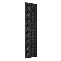
Statement 40XW - Loudspeaker Martin Logan - Free user manual and instructions
Find the device manual for free Statement 40XW Martin Logan in PDF.


| Product type | In-wall speaker |
| Brand | Martin Logan |
| Model | Statement 40XW |
| Frequency response | 48 – 25,000 Hz ± 3 dB |
| Sensitivity | 95 dB @ 2.83 V/m |
| Nominal impedance | 4 ohms (compatible with 4, 6 or 8 ohms) |
| Crossover frequencies | 300 Hz and 2700 Hz |
| High-frequency drivers | 16 x Obsidian XT driver |
| Mid-frequency drivers | 16 x 8.9 cm carbon cone with Nomex® support |
| Low-frequency drivers | 8 x 16.5 cm carbon cone with Nomex® support |
| Recommended amplifier power | 50 – 800 W |
| Maximum power | 400 W |
| Input terminals | Push style (two sets for easy installation) |
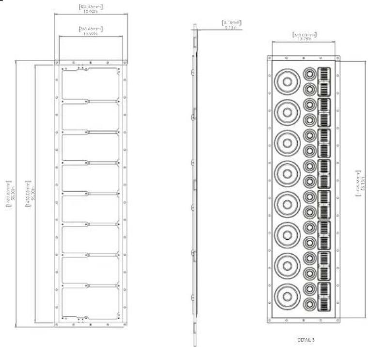
| Enclosure dimensions (W x H x D, without grille) | 14.3 x 84.2 x 3.4 in (361 x 2137 x 86 mm) |
| Grille dimensions (H x W) | 11.5 x 59.5 in (292 x 1511 mm) |
| Minimum wall cavity (height) | 89 in (2260 mm) |
| Minimum wall cavity (depth) | 3.5 in (89 mm) |
| Break-in | Approximately 72 hours at 90 dB |
| Crossover components | Custom air-core inductors, polypropylene film capacitors and low DF electrolytic capacitors |
| Weight | Not specified in manual (estimated ~30 kg) |
| Power supply | Passive – powered by external amplifier |
| Maintenance and cleaning | Dust grille with a soft cloth; do not expose to moisture |
| Safety | Turn off amplifier before any connection; do not exceed rated power |
| Spare parts and repairability | Contact Martin Logan after-sales service at (785) 749-0133 |
| General information | Installation requires 2 people; delivered in 3 boxes |
Frequently Asked Questions - Statement 40XW Martin Logan
User questions about Statement 40XW Martin Logan
0 question about this device. Answer the ones you know or ask your own.
Ask a new question about this device
Download the instructions for your Loudspeaker in PDF format for free! Find your manual Statement 40XW - Martin Logan and take your electronic device back in hand. On this page are published all the documents necessary for the use of your device. Statement 40XW by Martin Logan.
USER MANUAL Statement 40XW Martin Logan
Driver Assembly Manual
natural_image
Technical line drawing of a multi-panel electronic device with circular components and connectors (no text or symbols)WARNING!
• Refer servicing to a qualified technician.
- To prevent fire or shock hazard, do not expose this module to moisture.
- Turn the amplifier off should any abnormal conditions occur.
- Do not drive speaker beyond its rated power.


The lightning bolt flash with arrowhead symbol within an equilateral triangle is intended to alert the user to the presence of uninsulated "dangerous voltage" within the product's enclosure that may be of sufficient magnitude to constitute a risk of electric shock.

The exclamation point within an equilateral triangle is intended to alert the user to the presence of important operating and maintenance (servicing) instructions in the literature accompanying the appliance.

The fire within an equilateral triangle is intended to alert the user to the potential of creating a fire hazard if they do not follow the instructions.

The dollar sign within an equilateral triangle is intended to alert the user that they run the risk of causing damage that could be potentially expensive to repair if they don't follow the instructions.
Content Check List.... 3
Connection.... 4
Protect Your Investment. 4
Break-In. 4
Speaker Placement 4
Achieving Superior Imaging ....4
Balancing Hard vs. Soft Surfaces Improves
High- and Mid-Frequency Performance .....4
Painting the Speaker Grille 5
Pre-Installation Checklist 6
Part Identification 7
Installation 8 - 14
Driver Assembly Installation Preparation .....8
Attach Trim Pieces 9
Mounting The Driver Assembly .....10
Securing The Driver Assembly....11
Attach The Front Baffle Trim 12
(Optional) Apply The Logo Badge....13
(Optional) Apply The Speaker Grille .....14
Dimension Drawing.... 15
Specifications 16

Per the European Union WEEE (Waste Electrical and Electronic Equipment) directive effective August 13, 2005, we would like to notify you that this product may contain regulated materials which upon disposal, according to the WEEE directive, requires special reuse and recycling processing. For this reason, Martin Logan has arranged with our distributors in European Union member nations to collect and recycle this product at no cost to you.
To find your local distributor, please contact the dealer from whom you purchased this product, email info@martinlogan.com or visit the distributor locator at www.martinlogan.com.
Please note, only this product itself falls under the WEEE directive. When disposing of the packaging and other related shipping materials, we encourage you to recycle these items through the usual channels.
Content Check List
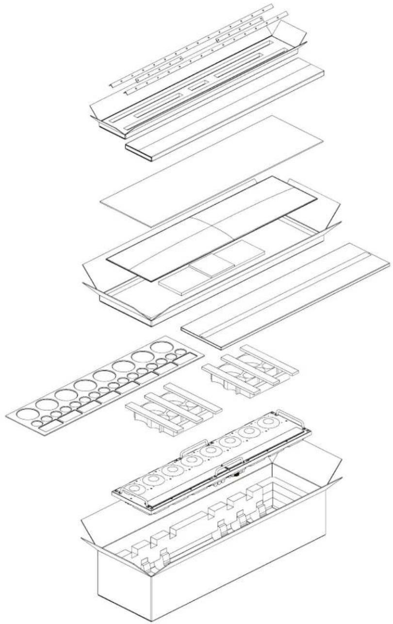
A complete Statement 40XW is shipped in 3 boxes. This manual refers to box 3 of 3 which is the Driver Assembly. The Statement 40XW Driver Assembly contains the following items.
Should you require assistance, please call our service department at (785) 749-0133.
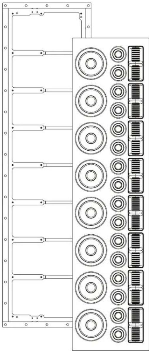
40XW Driver Assembly • Front Baffle Trim • Speaker Grille Cover • Extra Grille Scrim • Trim Pieces • Machine Screws 4x Brass Screws • MartinLogan Logo Badge and Template
natural_image
Exploded view diagram of a multi-level electronic device with internal components (no text or labels)CONNECTION
WARNING! Turn your amplifier off before making or breaking any signal connections!

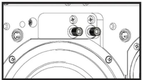
The amplifier is connected to the Statement 40XW through the binding posts located on the top or bottom of the in wall back box.
4 brass screws on the front of the speaker baffle are used to establish the connection with the amplifier.
See pg. 11 for additional details on making this connection.
natural_image
Technical line drawing of a mechanical component with multiple circular features and mounting holes (no text or symbols)Fig. 1
PROTECT YOUR INVESTMENT
- Use an amp that approximately matches the speaker's specified power handling.
- To avoid damage, turn down the volume of the speaker is distorting, sounds harsh, or the bass begins to break up.
- Tone controls and equalizers may increase the likelihood of distortion, especially at high volumes. Use these setting sparingly.
BREAK-IN
When you first begin to play your speakers, they may sound a bit bass shy, due to the high quality, long-life components used in the drivers. Allow approximately 72 hours of break-in at 90 dB (moderate listening levels) before any critical listening.
SPEAKER PLACEMENT
Achieving Superior Imaging
For best performance and imaging, place the speakers equidistant to the primary listening position. It is recommended that the primary listening position be 1x -2x the distance between the speakers for optimal imaging. For example, if your speakers are 10 feet apart, then the optimal listening distance is between 10 and 20 feet away. Guidance for speaker height can be found on page 6 in the "Pre-Installation Checklist" section.
Balancing Hard vs. Soft Surfaces Improves High- and
Mid-Frequency Performance
Rooms that are “overdamped” with carpeting, drapes, and other sound absorbers can cause your system to be dull and lifeless. On the other hand, rooms can have so many hard surfaces that the system sounds like a gymnasium. Experiment by adding or removing soft surfaces until you find a mix that is right for you.
PAINTING THE SPEAKER GRILLE
IMPORTANT! Before painting, remove the grille from speakers and remove the cloth scrim attached inside the grille. The speaker includes an extra scrim.
-
Remove the grille from the speaker. A protective cloth scrim is attached to the back of the grille with a low-tack adhesive. Remove this scrim by gently pulling it away from the grille and discard it.
-
Paint the grille, being careful not to plug the holes. Allow the paint to dry completely before proceeding. IMPORTANT! For best results use a spray rather than a brush or roller.
-
Gently press the new scrim into place before reinstalling the speaker grille.
PRE-INSTALLATION CHECKLIST
NOTE: This is the second part of the Installation process. Do not proceed until all steps in the "In-wall Back Box Manual" have been completed.
If using the Statement On-Wall Enclosure you may proceed from Step 17.
Required Tools:
-3/32 Hex Bit (Not Included)
-5/32 Hex Bit (Not Included)
-Power Drill
-#2 Philips Bit
-#2 Hand Screwdriver
-Medium Grit Sanding Sponge
PLEASE NOTE: INSTALLATION IS A 2 PERSON JOB.
PART IDENTIFICATION
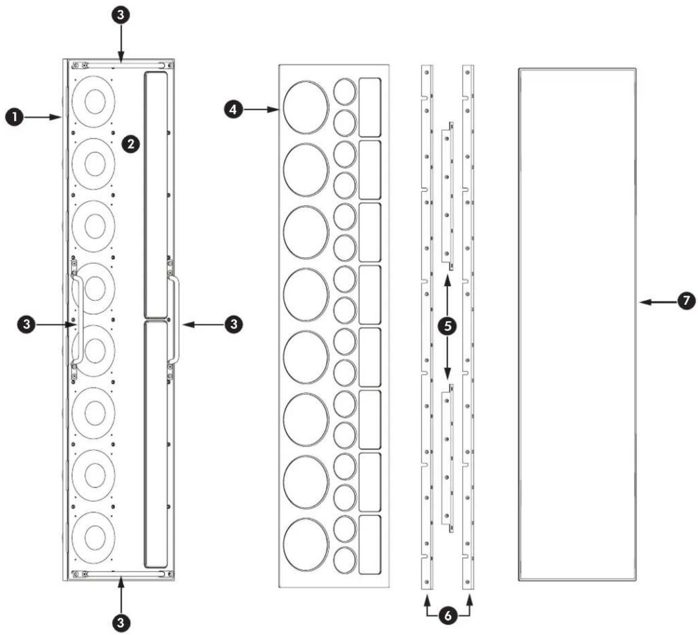
1 Driver Assembly
2 Baffle Protector
3 Handles
4 Trim Baffle
5 End Trim
6 Side Trim
7 Grille
SPEAKER INSTALLATION
STEP 16: DRIVER ASSEMBLY INSTALLATION PREPARATION
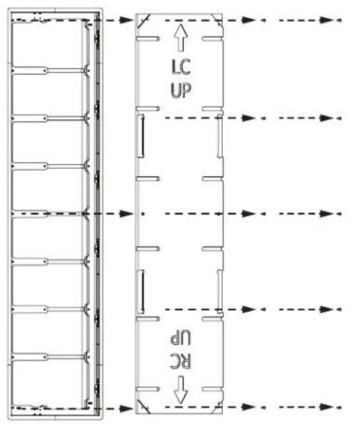
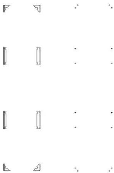
16a To prepare the back box for the driver assembly installation, first remove the positioning brackets, 2 corner brackets, and 4 side brackets using a Phillips screwdriver. These brackets are held in place with 2 screws each.
16b Remove the 10 screws securing the positioning board and then carefully remove it from the back box.
natural_image
Pure geometric line patterns with no text, numbers, or symbolsSTEP 17: ATTACH TRIM PIECES
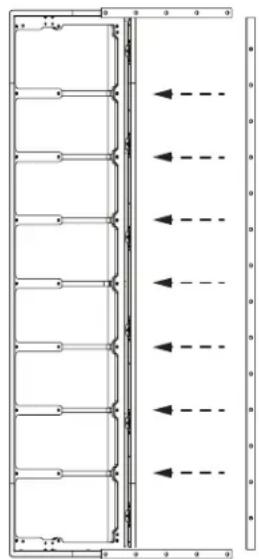
17a Before applying the trim pieces, check the interior metal edge of the install board opening. Sand away any sheet rock mud buildup so the trim will sit flush with the surface.
17b Using #2 Phillips screwdriver. apply the top and bottom trim pieces first, using the supplied machine screws. (These screws will be in the trim packaging.)
17c Apply the side trim pieces the same way as the top and bottom pieces.
NOTE: If using the optional on-wall enclosure instead of the in-wall installation method, please ignore any references to sheet rock or sheet rock mud, as they only apply to the in-wall method of installation. All other steps apply to both methods of installation.
natural_image
Pure electrical circuit lines without any symbols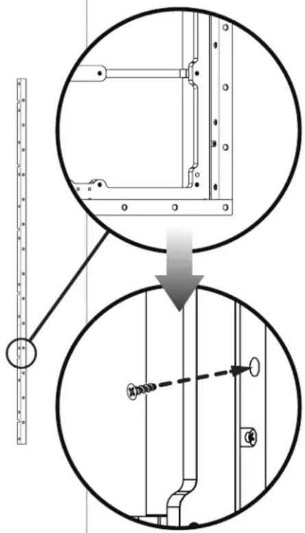
STEP 18: MOUNTING THE DRIVER ASSEMBLY
THIS STEP REQUIRES 2 PEOPLE TO COMPLETE SAFELY
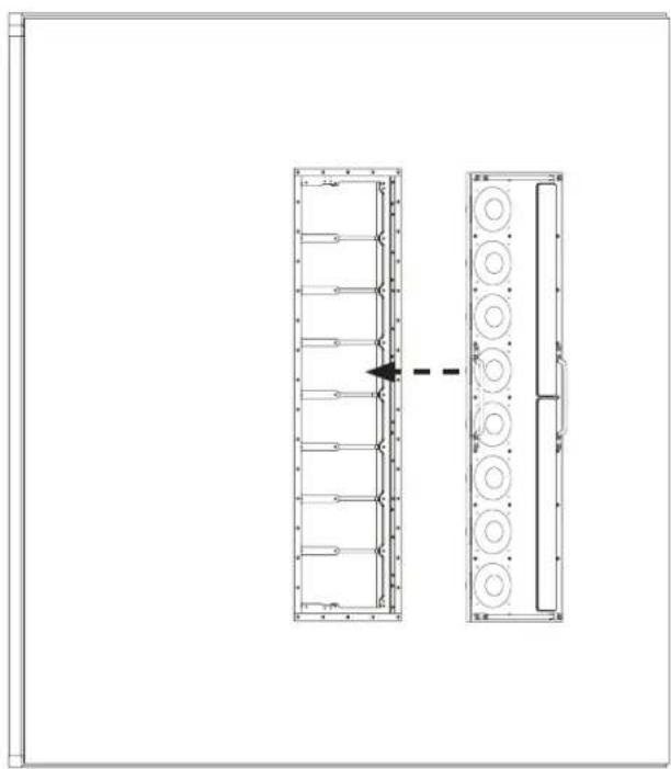
18a With 2 people, lift the driver assembly from its packaging using the attached handles.
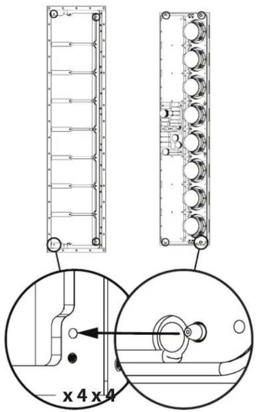
18b With 2 people, carefully seat the driver assembly into the back box by guiding the driver assembly alignment pins into the mating holes on the back box. Be careful not to damage the wall surface during this step.
18c While 1 person continues to hold the driver assembly securely in place, the other should install the included 8-32 screws through the driver assembly into the back box. These specific locations are marked as "through" holes in the attached plastic baffle protector. (3/32 hex driver bit required for machine screws. Not included)
18d Once all 8-32 screws have been tightened, the driver assembly is now securely attached to the back box. The person holding the driver assembly in place can now let go.
18e You may now safely remove the handles and plastic baffle protector from the driver assembly. (Handle removal will require the 5/32 hex driver bit. Not included.)
NOTE: Left channel orientation shown here. Right channel will be mirrored.
natural_image
Technical line drawing of a dual-panel electronic device with circular components, no text or symbols present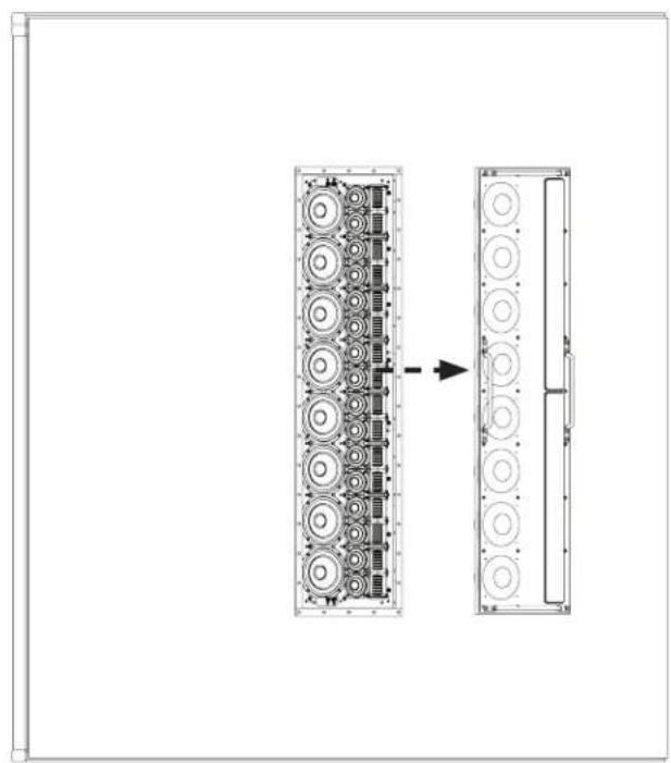
natural_image
Diagram showing two views of a multi-chamber electronic device with circular components, one with an arrow indicating transformation (no text or symbols present)STEP 19: SECURING THE DRIVER ASSEMBLY
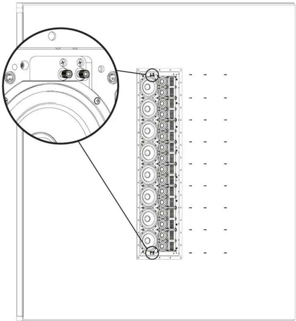
19a After removing the handles and baffle protector, secure the remaining (27 total) included machine screws.
19b To establish the speaker wire connection with the back box, carefully tighten the included brass contact screws with a Phillips screw driver. There are a total of (4) brass contact screws that need to be installed. 2 on top, and 2 on bottom. These screw holes are located directly above the top bass driver and directly below the bottom bass driver.
NOTE: The speaker will not play if these screws are not installed.
19c The binding posts located on the front of the Driver Assembly should only be used for temporary/troubleshooting purposes and are not intended to be used during normal operation and can otherwise be ignored.
STEP 20: ATTACH THE FRONT BAFFLE TRIM
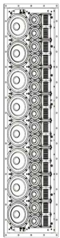
20a Carefully align the front baffle trim over the drivers and press firmly in place to secure.
natural_image
Technical line drawing of a multi-layered mechanical or electrical component assembly (no text or symbols)
natural_image
Pure diagram of vertical rectangles with circles inside, no text or symbols presentSTEP 21 (OPTIONAL): APPLY THE LOGO BADGE
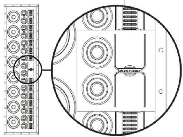
21a Using the included badge application template, attach the logo to the front baffle trim. This step is optional.
natural_image
Top-down schematic of a mechanical or electrical component layout with circular components and a central U-shaped component, no text or symbols present.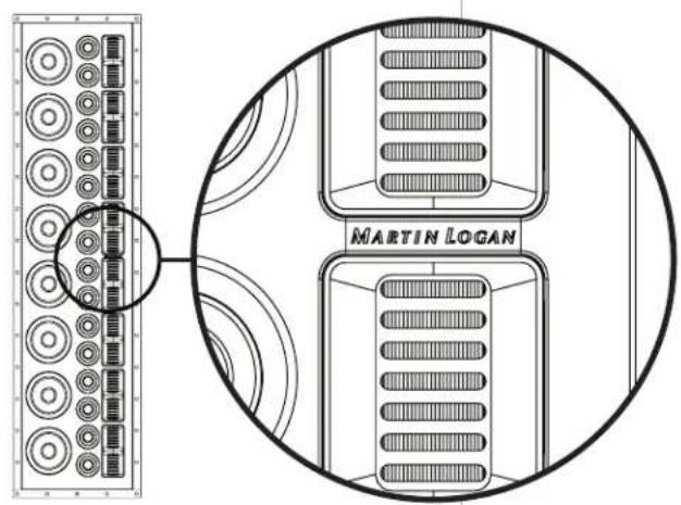
STEP 22 (OPTIONAL): APPLY THE SPEAKER GRILLE
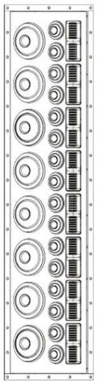
22a Gently place the speaker grille over the front baffle, ensuring a proper fit. The grille is secured with magnets and may be removed at any time, as desired. For those wanting to display the drivers of the Statement 40XW, the grille can remain off. For installations behind an acoustically transparent screen it is recommended that the grille remain off.
natural_image
Pure electrical circuit lines without any symbols
natural_image
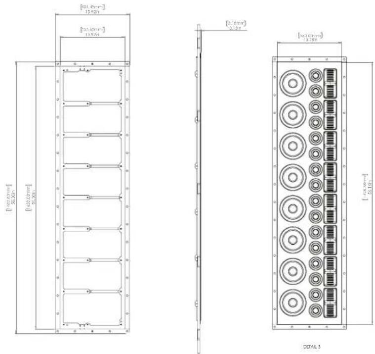
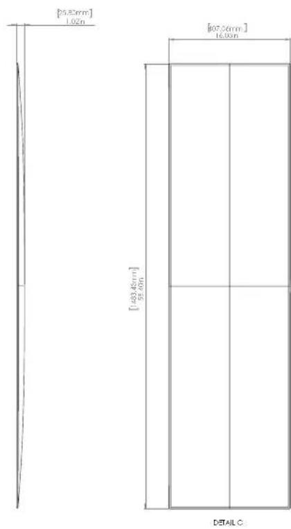
Blank white image with a thin gray border (no text, symbols, or markings)DIMENSIONS
SPECIFICATIONS
Frequency Response: 48–25,000 Hz ± 3 dB
Tweeter Dispersion (horizontal x vertical).....80° x 52-inch line source
Sensitivity....95 dB @ 2.83 volts/ meter
Impedance....4 ohms. Compatible with 4, 6, or 8 ohm rated amps
Crossover Frequencies....300, 2700 Hz
High-Frequency Drivers......Sixteen Folded Motion XT Obsidian Tweeters
Mid-Frequency Drivers......Sixteen 3.5-inch (8.9 cm) unidirectional carbon fiber multi-section cone with Nomex® backer and cast aluminum basket, sealed back chamber format. Concave dust cap
Low-Frequency Drivers.....Eight 6.5-inch (16.5 cm) unidirectional carbon fiber multi-section cone with Nomex® backer and cast aluminum basket, sealed back chamber format. Concave dust cap
Binding Post Inputs....Push style (two sets for easy installation)
Crossover Components....Custom air core coil inductors, polypropylene film capacitors, and low DF electrolytic capacitors.
Suitable Amplifier Range....50–800 watts
Max Power Handling......400 watts
Weight.... 150 lb (68.1 kg)
Required Wall Cavity....(width) Minimum: 14.5 inch (368 mm) Maximum: 16.5 inch (420 mm)
Required Wall Cavity....(height, unobstructed) Minimum: 89 inch (2260 mm)
Required Wall Cavity....(depth) Minimum: 3.5 inch (89 mm)
Enclosure (width x height x depth, excludes padding)...14.3 x 84.2 x 3.4 inch (361 x 2137 x 86mm)
Grille (height x width).... 11.5 x 59.5 inch (292 x 1511 mm)
*Specifications are subject to change without notice
Statement 40XW
natural_image
Technical line drawing of a multi-panel electronic device with circular components and connectors (no text or symbols)AVERTISSEMENT!
natural_image
Exploded view diagram of a multi-level electronic device with internal components (no text or labels)RACCORDEMENT
natural_image
Technical line drawing of a mechanical component with circular features and mounting holes (no text or symbols)Fig. 1
PROTÉGEZ VOTRE INVESTISSEMENT
natural_image
Pure geometric line patterns with no text, numbers, or symbolsÉTAPE 17: ATTACHEZ LES PIÈCES DE LA PAROI
natural_image
Pure electrical circuit lines without any symbols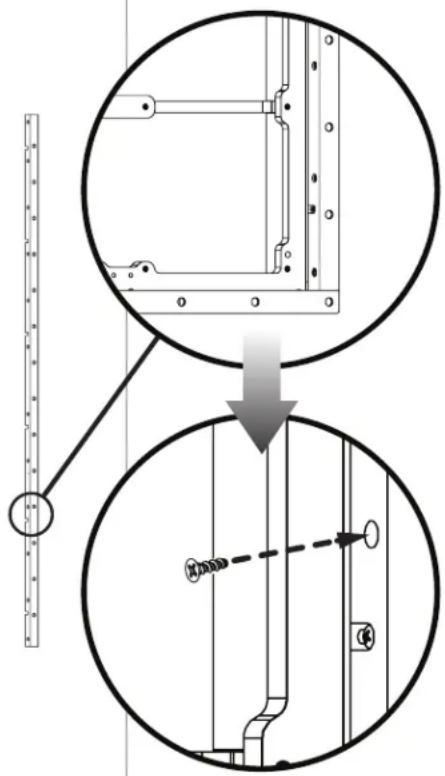
STEP 18: MONTAGE DE L'ENSEMBLE DU HAUT-PARLEUR
CETTE ÉTAPE NÉCESSITE 2 PERSONNES POUR LA RÉALISER EN TOUTE SÉCURITÉ
natural_image
Technical line drawing of two rectangular panels with internal structural elements, one with a dashed arrow pointing to a circular component (no text or symbols)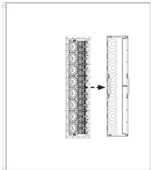
natural_image
Diagram showing two rectangular panels with circular components, one with an arrow pointing to a larger panel (no text or symbols present)STEP 19: FIXEZ L'ENSEMBLE DU HAUT-PARLEUR
ÉTAPE 20 : ATTACHEZ LA PAROI AVANT DU BAFFLE
natural_image
Technical line drawing of a multi-layered mechanical or electrical component assembly (no text or symbols)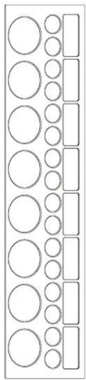
natural_image
Pure diagram of vertical rectangles with circles inside, no text or symbols presentÉTAPE 21 (FACULTATIF) APPLIQUEZ LE BADGE DU LOGO
natural_image
Top-down schematic of a mechanical or electrical component layout with circular components and a central U-shaped component, no text or symbols present.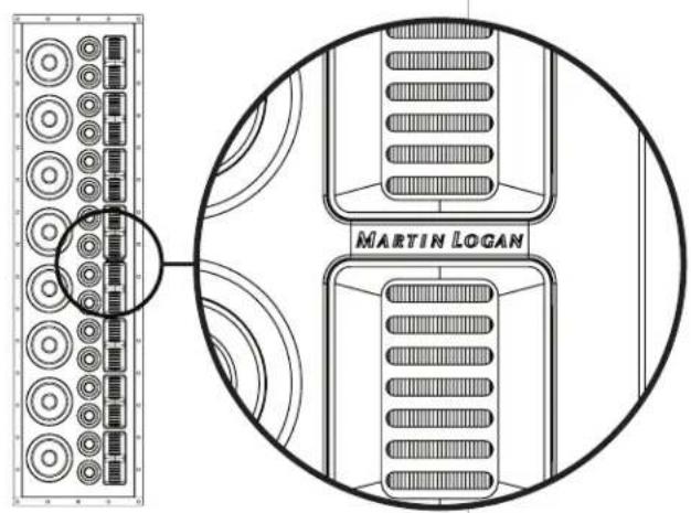
ÉTAPE 22 : (FACULTATIF) APPLIQUEZ LA GRILLE DU HAUT-PARLEUR
natural_image
Pure electrical circuit lines without any symbols
natural_image
Blank white image with a thin border (no text, symbols, or markings)DESSIN DIMENSIONNEL
![[25.83mm] 1.02m [483.45mm] 92.60m [67.66mm] 16.00m DETAILC](/content/2026/04/596185/images/a18037d9a8f95cff80636ad732ac326fe30aea53cdc2530dc90b2b327510b7e8.jpg)
SPÉCIFICATIONS
Poids 150 lb (68.1 kg)
Cavité murale requise .... (largeur) Minimum: 14.5 inch (368 mm) Maximum: 16.5 inch (420 mm)



- WARNING!
- Content Check List
- CONNECTION
- PROTECT YOUR INVESTMENT
- BREAK-IN
- SPEAKER PLACEMENT
- Achieving Superior Imaging
- Balancing Hard vs. Soft Surfaces Improves High- and
- Mid-Frequency Performance
- PAINTING THE SPEAKER GRILLE
- PRE-INSTALLATION CHECKLIST
- Required Tools:
- PART IDENTIFICATION
- SPEAKER INSTALLATION
- STEP 16: DRIVER ASSEMBLY INSTALLATION PREPARATION
- STEP 17: ATTACH TRIM PIECES
- STEP 18: MOUNTING THE DRIVER ASSEMBLY
- THIS STEP REQUIRES 2 PEOPLE TO COMPLETE SAFELY
- STEP 19: SECURING THE DRIVER ASSEMBLY
- STEP 20: ATTACH THE FRONT BAFFLE TRIM
- STEP 21 (OPTIONAL): APPLY THE LOGO BADGE
- STEP 22 (OPTIONAL): APPLY THE SPEAKER GRILLE
- SPECIFICATIONS
- Statement 40XW
- AVERTISSEMENT!
- RACCORDEMENT
- PROTÉGEZ VOTRE INVESTISSEMENT
- ÉTAPE 17: ATTACHEZ LES PIÈCES DE LA PAROI
- STEP 18: MONTAGE DE L'ENSEMBLE DU HAUT-PARLEUR
- CETTE ÉTAPE NÉCESSITE 2 PERSONNES POUR LA RÉALISER EN TOUTE SÉCURITÉ
- STEP 19: FIXEZ L'ENSEMBLE DU HAUT-PARLEUR
- ÉTAPE 20 : ATTACHEZ LA PAROI AVANT DU BAFFLE
- ÉTAPE 21 (FACULTATIF) APPLIQUEZ LE BADGE DU LOGO
- ÉTAPE 22 : (FACULTATIF) APPLIQUEZ LA GRILLE DU HAUT-PARLEUR
- SPÉCIFICATIONS
Brand : Martin Logan
Model : Statement 40XW
Category : Loudspeaker