
KT48XT - Range hood BERTAZZONI - Free user manual and instructions
Find the device manual for free KT48XT BERTAZZONI in PDF.
| Product Type | Decorative Range Hood |
| Brand | Bertazzoni |
| Model | KT48XT |
| Width | 48 inches (122 cm) |
| Depth | 20 inches (51 cm) |
| Height (minimum with telescopic chimney) | 24 inches above electric surface, 30 inches for gas |
| Estimated Weight | Approximately 15 kg (33 lbs) |
| Power Supply | 120 V ~ 60 Hz, 15 A, dedicated circuit |
| Motor Power | Not specified, but designed for efficient exhaust |
| Speeds | 4 speeds: low, medium, high, intensive (10 min) |
| Delayed Shut-off | Yes, 15 minutes (3i button pressed for 2s) |
| Remote Control | Included, LR03-AAA battery not supplied |
| Lighting | LED, on/off switch |
| Filtration | Metal grease filters (dishwasher-safe) + optional charcoal filter for recirculation |
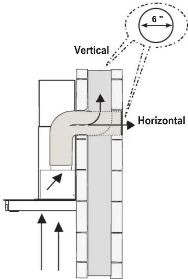
| Exhaust Duct Diameter | 6 inches (15 cm), rigid metal recommended |
| Exhaust Mode | External exhaust or recirculation (charcoal kit required) |
| Warranty | 2-year limited (parts and labor) |
| Installation | Wall-mounted, telescopic chimney included |
| Included Accessories | Chimney supports, damper flaps, remote control, manual |
| Metal Filter Maintenance | Clean every 2 months, dishwasher-safe |
| Charcoal Filter Replacement | Every 4 months, kit #901497 |
Frequently Asked Questions - KT48XT BERTAZZONI
User questions about KT48XT BERTAZZONI
0 question about this device. Answer the ones you know or ask your own.
Ask a new question about this device
Download the instructions for your Range hood in PDF format for free! Find your manual KT48XT - BERTAZZONI and take your electronic device back in hand. On this page are published all the documents necessary for the use of your device. KT48XT by BERTAZZONI.
USER MANUAL KT48XT BERTAZZONI
INSTALLATION AND USER MANUAL
WALLMOUNT T-SHAPE DESIGN HOODS

BERTAZZONI
INSTRUCTIONS D'INSTALLATION ET D'UTILISATION
HOTTES MURALES T-FORME


KT..XT
Section Page
IMPORTANT SAFETY INSTRUCTIONS 3
RANGE HOOD DIMENSIONS 6
INSTALLATION HEIGHT REQUIREMENTS 7
PARTS 8
TOOLS NEEDED 10
VENTING METHOD 11
INSTALLING 12
CHOOSING VENTING METHOD 17
ATTACH VENTING: VENTED 18
ATTACH VENTING: RECIRCULATING 22
CLEANING STAINLESS STEEL 29
CARING FOR FILTERS 29
REPLACING THE ACTIVATED CHARCOAL FILTER 30
REPLACING BULBS 30
WIRING DIAGRAM 31
WARRANTY 32
READ AND SAVE THESE INSTRUCTIONS BEFORE YOU START INSTALLING THIS Range Hood
WARNING: - TO REDUCE THE RISK OF A RANGE TOP GREASE FIRE:
a) Never leave surface units unattended at high settings. Boilovers cause smoking and greasy spillovers that may ignite. Heat oils slowly on low or medium setting.
b) Always turn hood ON when cooking at high heat or when flambeing food (i.e. Crepes Suzette, Cherries Jubilee, Peppercorn Beef Flambé).
c) Clean ventilating fans frequently. Grease should not be allowed to accumulate on fan or filter.
d) Use proper pan size. Always use cookware appropriate for the size of the surface element.
WARNING: - TO REDUCE THE RISK OF INJURY TO PERSONS IN THE EVENT OF A RANGE TOP GREASE FIRE, OBSERVE THE FOLLOWING*:
a) SMOTHER FLAMES with a close-fitting lid, cookie sheet, or metal tray, then turn off the burner. BE CAREFUL TO PREVENT BURNS. If the flames do not go out immediately EVACUATE AND CALL THE FIRE DEPARTMENT.
b) NEVER PICK UP A FLAMING PAN - You may be burned.
c) DO NOT USE WATER, including wet dishcloths or towels - a violent steam explosion will result.
d) Use an extinguisher ONLY if:
a) SMOTHER FLAMES with a close-fitting lid, cookie sheet, or metal tray, then turn off the burner. BE CAREFUL TO PREVENT BURNS. If the flames do not go out immediately EVACUATE AND CALL THE FIRE DEPARTMENT. b) NEVER PICK UP A FLAMING PAN - You may be burned. c) DO NOT USE WATER, including wet dishcloths or towels - a violent steam explosion will result. d) Use an extinguisher ONLY if:
-
You know you have a Class ABC extinguisher, and you already know how to operate it.
-
The fire is small and contained in the area where it started.
-
The fire department is being called.
-
You can fight the fire with your back to an exit.
* Based on "Kitchen Firesafety Tips" published by NFPA
WARNING - TO REDUCE THE RISK OF FIRE OR ELECTRIC SHOCK, do not use this fan with any solid-state speed control device.
WARNING - TO REDUCE THE RISK OF FIRE, ELECTRICAL SHOCK, OR INJURY TO PERSONS, OBSERVE THE FOLLOWING:
- Use this unit only in the manner intended by the manufacturer. If you have any questions, contact the manufacturer.
- Before servicing or cleaning unit, switch power off at service panel and lock the service disconnecting means to prevent power from being switched on accidentally. When the service disconnecting means cannot be locked, securely fasten a prominent warning device, such as a tag, to the service panel.
CAUTION: For General Ventilating Use Only. Do Not Use To Exhaust Hazardous or Explosive Materials and Vapors.
WARNING - TO REDUCE THE RISK OF FIRE, ELECTRICAL SHOCK, OR INJURY TO PERSONS, OBSERVE THE FOLLOWING:
- Installation Work And Electrical Wiring Must Be Done By Qualified Person(s) In Accordance With All Applicable Codes And Standards, Including Fire-Rated Construction.
- Sufficient air is needed for proper combustion and exhausting of gases through the flue (chimney) of fuel burning equipment to prevent backdrafting. Follow the heating equipment manufacturer's guideline and safety standards such as those published by the National Fire Protection Association (NFPA), and the American Society for Heating, Refrigeration and Air Conditioning Engineers (ASHRAE), and the local code authorities.
- When cutting or drilling into wall or ceiling, do not damage electrical wiring and other hidden utilities.
- Ducted fans must always be vented to the outdoors.
ALL WALL AND FLOOR OPENINGS WHERE THE Range Hood IS INSTALLED MUST BE SEALED.
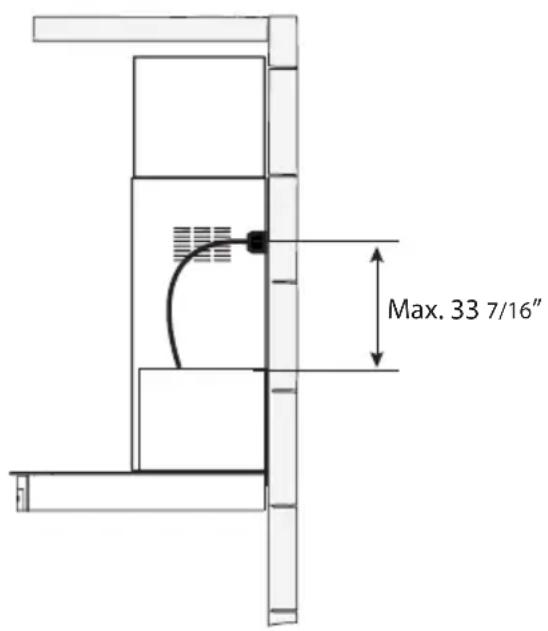
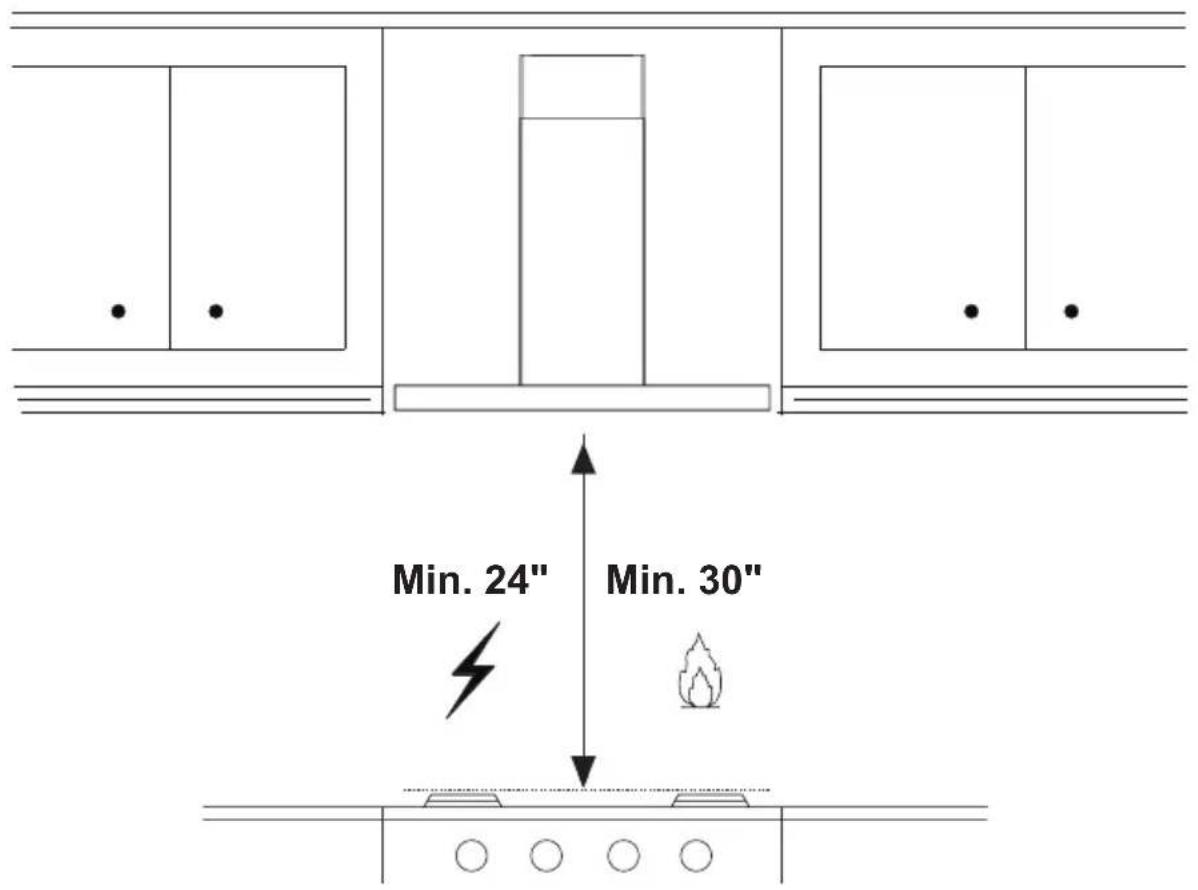
This Range Hood requires at least 24" of clearance between the bottom of the Range Hood and the cooking surface or countertop. This hood has been approved by UL at this distance from the cooktop. This minimum clearance may be higher depending on local building codes. For gas cooktops and combination ranges, a minimum of 30" is recommended and may be required.
Overhead cabinets on both sides of this unit must be a minimum of 18" above the cooking surface or countertop. Consult the cooktop or range installation instructions given by the manufacturer before making any cutouts.
MOBILE HOME INSTALLATION The installation of this Range Hood must conform to the Manufactured Home Construction and Safety Standards, Title 24 CFR, Part 3280 (formerly Federal Standard for Mobile Home Construction and Safety, Title 24, HUD, Part 280). See Electrical Requirements"
VENTING REQUIREMENTS
Determine which venting method is best for your application. Ductwork can extend either through the wall or the roof.
The length of the ductwork and the number of elbows should be kept to a minimum to provide efficient performance. The size of the ductwork should be uniform. Do not install two elbows together. Use duct tape to seal all joints in the ductwork system. Use caulking to seal exterior wall or floor opening around the cap.
Flexible ductwork is not recommended. Flexible ductwork creates back pressure and air turbulence that greatly reduces performance.
Make sure there is proper clearance within the wall or floor for exhaust duct before making cutouts. Do not cut a joist or stud unless absolutely necessary. If a joist or stud must be cut, then a supporting frame must be constructed.
WARNING - To Reduce The Risk Of Fire, Use Only Metal Ductwork.
CAUTION - To reduce risk of fire and to properly exhaust air, be sure to duct air outside – Do not vent exhaust air into spaces within walls or ceilings or into attics, crawl spaces, or garages.
Cold Weather installations
An additional back draft damper should be installed to minimize backward cold air flow and a nonmetallic thermal break should be installed to minimize conduction of outside temperatures as part of the vent system. The damper should be on the cold air side of the thermal break. The break should be as close as possible to where the vent system enters the heated portion of the house.
WARNING
- Venting system MUST terminate outside the home.
- DO NOT terminate the ductwork in an attic or other enclosed space.
- DO NOT use 4" laundry-type wall caps.
- Flexible-type ductwork is not recommended.
- DO NOT obstruct the flow of combustion and ventilation air.
- Failure to follow venting requirements may result in a fire.
ELECTRICAL REQUIREMENTS
A 120 volt, 60 Hz AC-only electrical supply is required on a separate 15 amp fused circuit. A time-delay fuse or circuit breaker is recommended. The fuse must be sized per local codes in accordance with the electrical rating of this unit as specified on the serial/rating plate located inside the unit near the field wiring compartment.

WARNING
• Electrical ground is required on this Range Hood.
- If cold water pipe is interrupted by plastic, nonmetallic gaskets or other materials, DO NOT use for grounding.
• DO NOT ground to a gas pipe.
- DO NOT have a fuse in the neutral or grounding circuit. A fuse in the neutral or grounding circuit could result in electrical shock.
- Check with a qualified electrician if you are in doubt as to whether the Range Hood is properly grounded.
- Failure to follow electrical requirements may result in a fire.
State of California Proposition 65 Warning (US only)
WARNING
This product contains chemicals known to the State of California to cause cancer and birth defects or other reproductive harm.
For more information go to www.P65Warnings.ca.gov
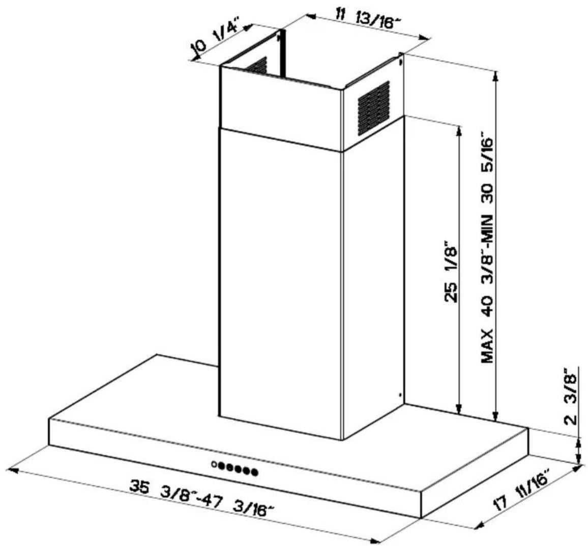

MIN. 24" OVER ELECTRIC MIN. 30" OVER GAS
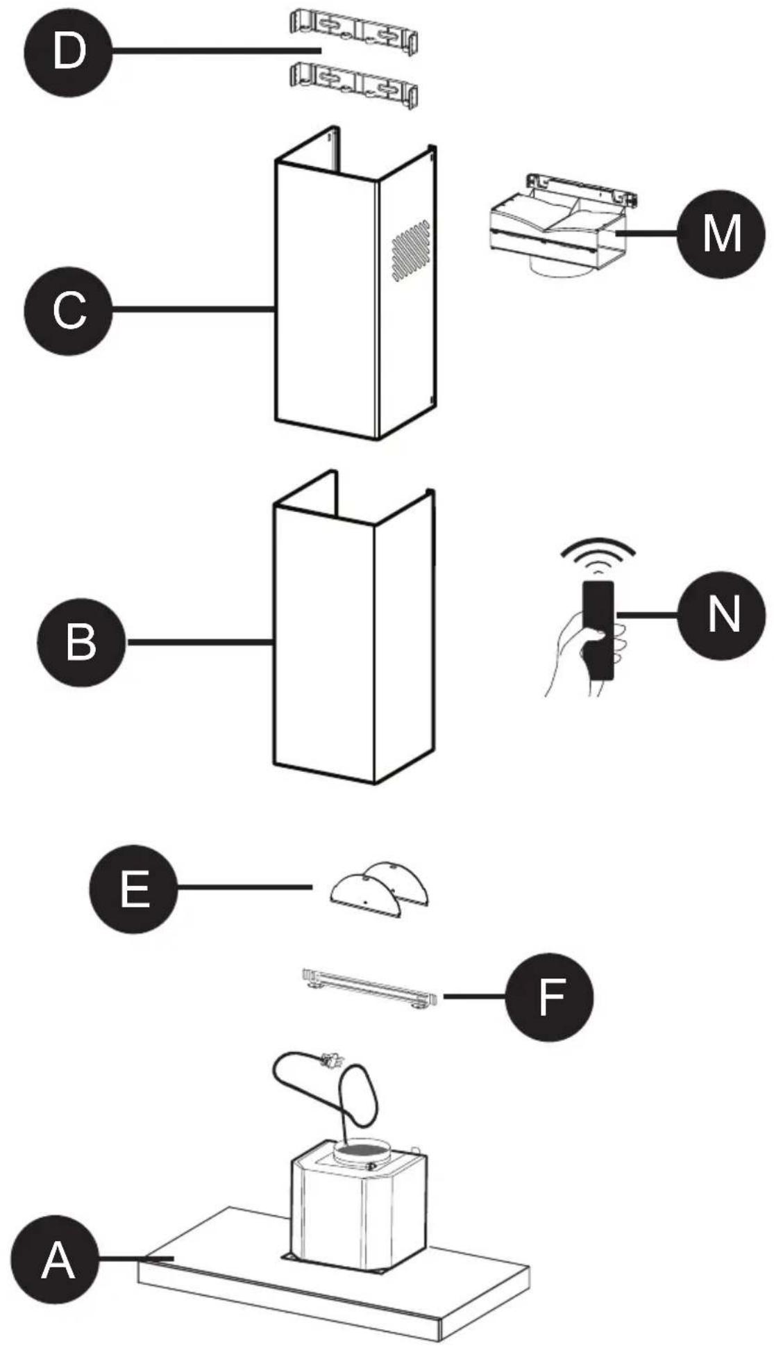
PARTS INCLUDED
| REF. | PART | QTY |
| A | Hood body | 1 |
| B | Telescopic Lower Chimney | 1 |
| C | Telescopic Upper Chimney | 1 |
| D | Chimney Brackets | 2 |
| E | Damper Flaps | 2 |
| F | Hood wall Brackets | 1 |
| M | Ductless Diverter 1 | |
| N | Remote Control 1 |
| REF | PART | ||
| G | Pozi Screws 3/16" x 1 3/4" | 6 | |
| H | Pozi Screws (1/8" x 3/16") | 2 | |
| I | Torx Screws 1/8" x 7/16" | 4 | |
| L | Torx Screws (1/4" x 2 3/4") | 2 | |
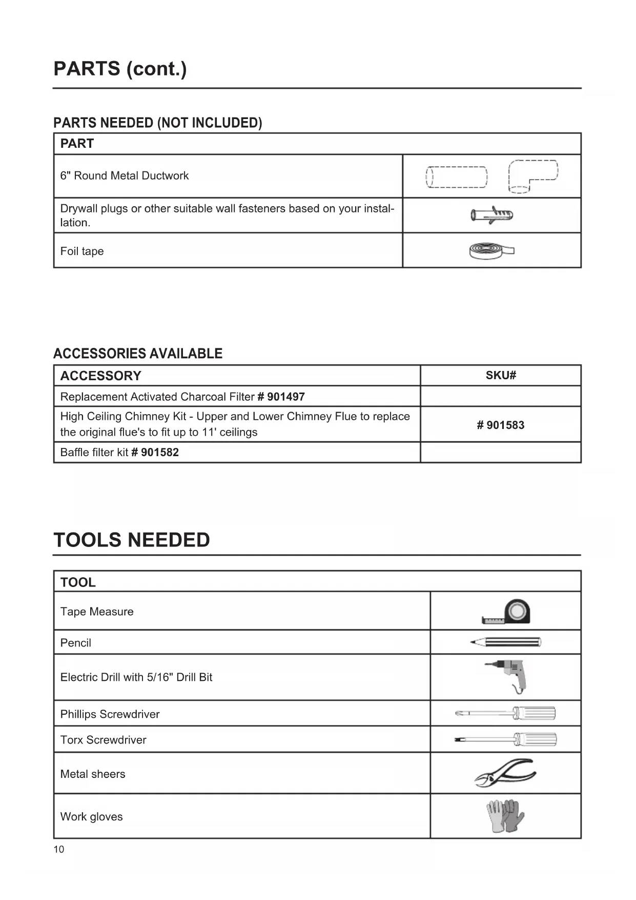
PARTS NEEDED (NOT INCLUDED)
| PART | |
| 6" Round Metal Ductwork |   |
| Drywall plugs or other suitable wall fasteners based on your installation. |  |
| Foil tape |  |
ACCESSORIES AVAILABLE
| ACCESSORY | SKU# |
| Replacement Activated Charcoal Filter # 901497 | |
| High Ceiling Chimney Kit - Upper and Lower Chimney Flue to replace the original flue's to fit up to 11' ceilings | # 901583 |
| Baffle filter kit # 901582 |
TOOLS NEEDED
| TOOL | |
| Tape Measure |  |
| Pencil |  |
| Electric Drill with 5/16" Drill Bit |  |
| Phillips Screwdriver |  |
| Torx Screwdriver |  |
| Metal sheers |  |
| Work gloves |  |
1 VENTED
RECIRCULATING
Requires purchase of Activated Charcoal Accessory kit # 901497.
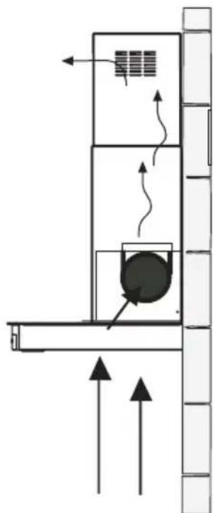
natural_image
Diagram of a mechanical or architectural component with directional arrows and internal flow indicators (no text or symbols)
DRAW CENTER LINES
Draw a vertical line ✗ on the supporting wall to the ceiling or upper limit, at the center of the area in which the hood will be installed.
Draw a horizontal line Y where the bottom edge of the hood will be located, a minimum of 24" above an electric cooking surface and 30" above a gas cooking surface.
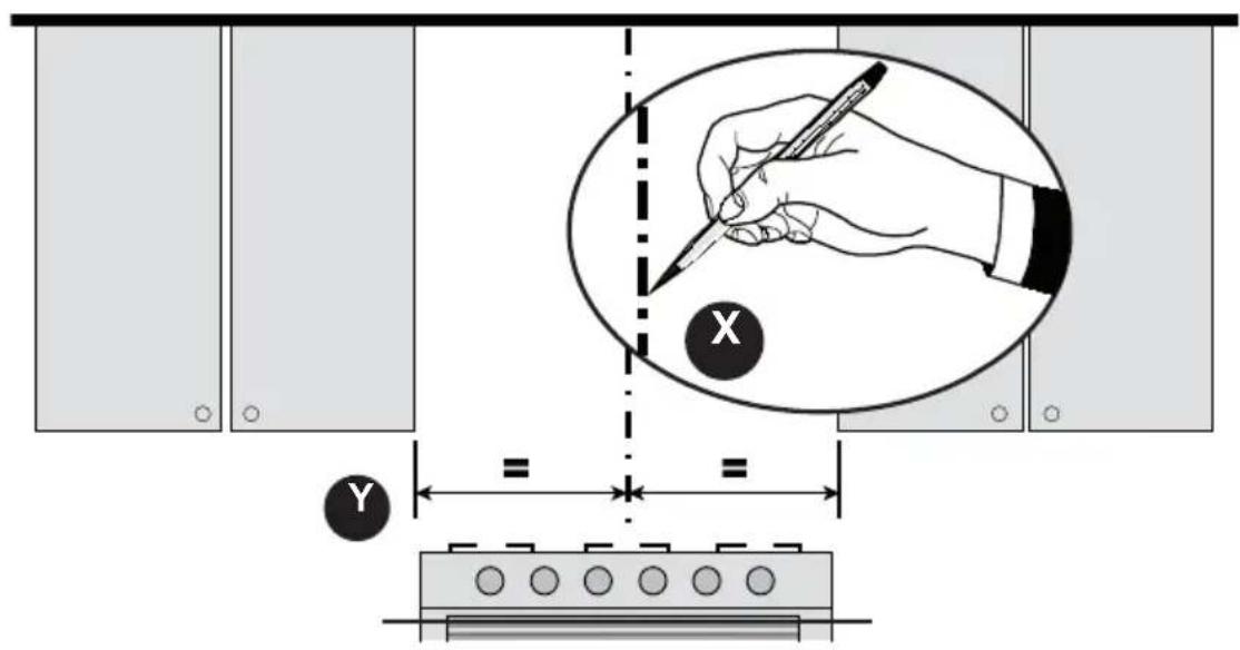
MIN. 24" OVER ELECTRIC/MIN. 30" OVER GAS

3
- Place a bracket D on the wall as shown about 1/8" from the ceiling or upper limit, aligning the center (notch) with the vertical reference line x and mark the wall at the centers of the holes in the bracket.
- Place the second bracket D on the wall as shown, below the first bracket, at the height of the upper chimney section C supplied and aligning the center (notch) with the vertical line.
- Mark the wall at the centers of the holes in the bracket and mark the point 1 and 2 for the Hood Body installation as shown(12 5/8" from the horizontal line and 4 9/16" from the vertical line).
- Drill 5/16" holes at all the center points marked (point 1,2,3,4,5,6) as shown.
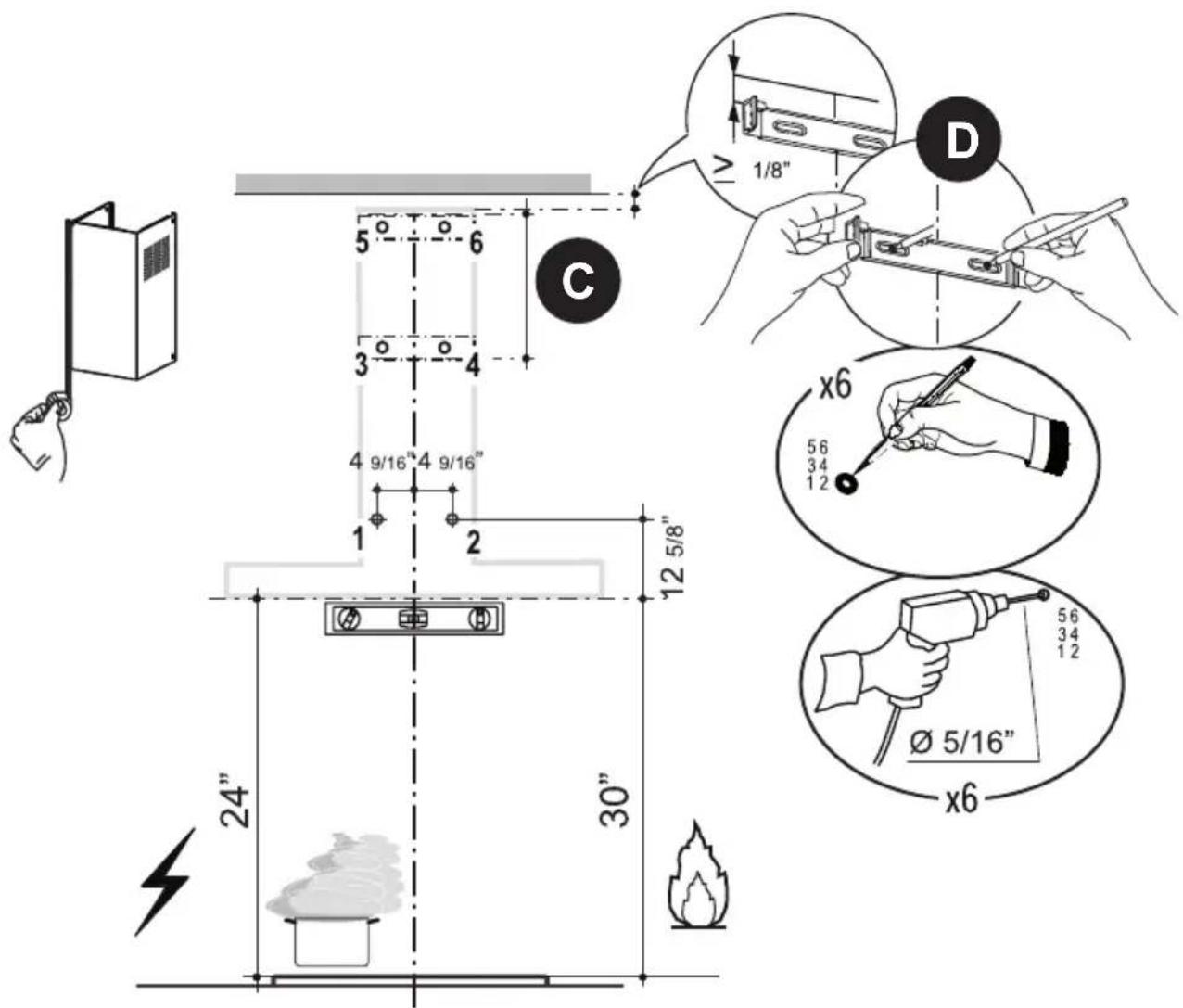

Installation screws provided must be secured with wall plugs (purchase separately).
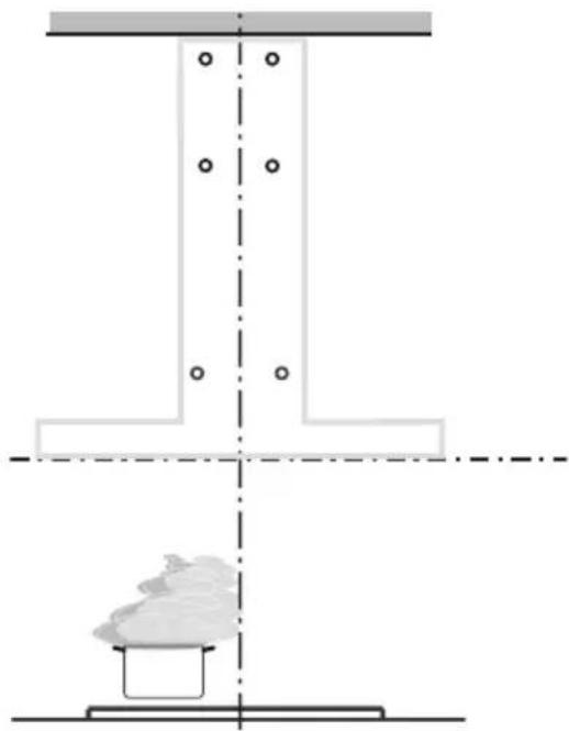
natural_image
Diagram of a structural steel I-beam with a base and top view showing internal components (no text or labels)
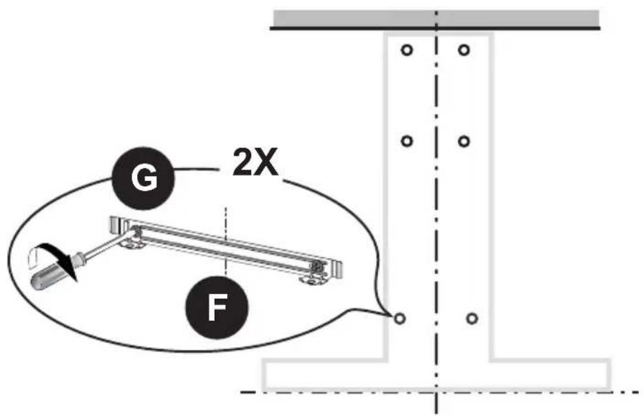
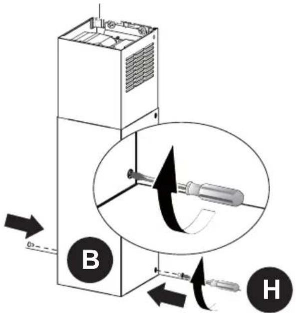
Insert the two screws G supplied with the hood into the Wall Bracket F as shown and do not tighten all the way to wall leaving 3/16" of the screw heads exposed.
| Phillips Screwdriver |

Use a level to insure that Wall Bracket F is level and then fully secure the two screws.


Hook the hood body onto the hood wall bracket F.

8
Tighten the 2 screws H as shown.
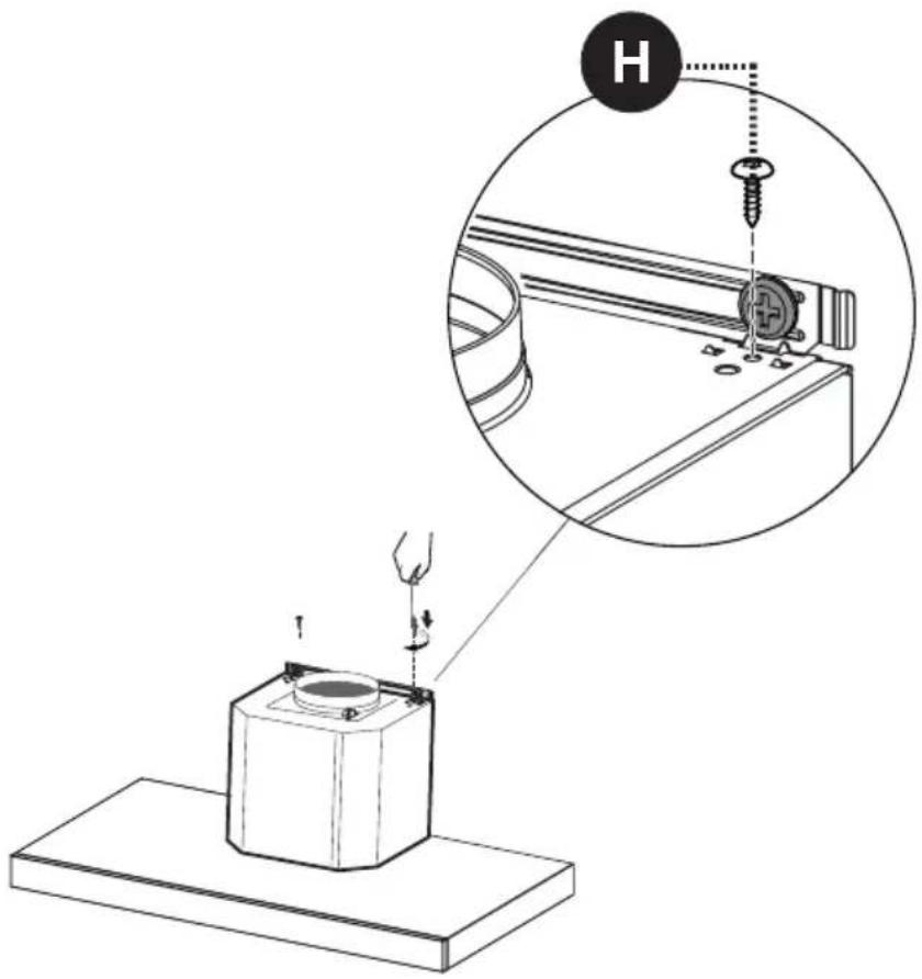
| Phillips Screwdriver |
VENTED
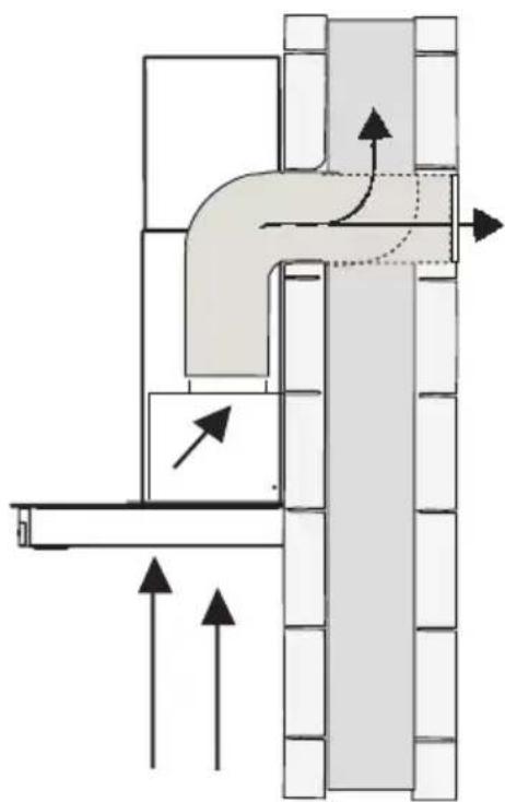
natural_image
Technical diagram of a pipe connection with directional arrows indicating flow or movement (no text or symbols present)Go to Pg.18
RECIRCULATING
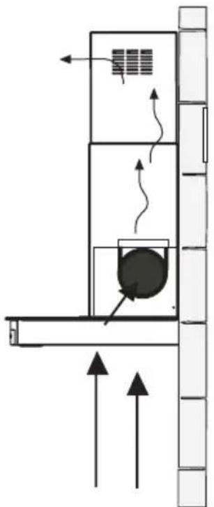
natural_image
Diagram of a vertical structure with internal components and directional arrows, no text or symbols presentGo to Pg.22
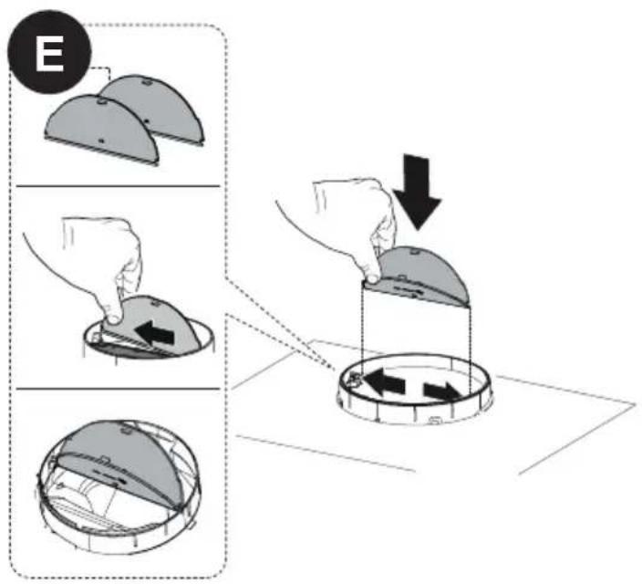
1 Install the Damper flaps E that are included with hood by snapping the tabs into place inside the top of the hood before connecting ductwork.
2
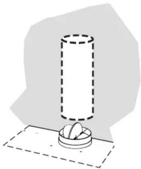
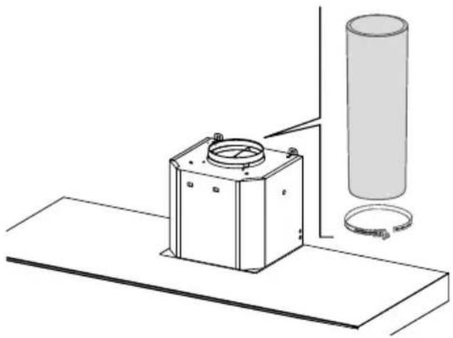
Install Roof or Wall Cap purchased separately. Connect the 6" metal ductwork to the Roof or Wall Cap and then attach ductwork. Seal with foil tape.
natural_image
Simple line drawing of a cylinder placed on a base with two circular objects, against a plain background (no text or symbols)
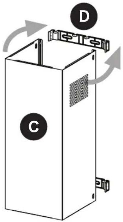
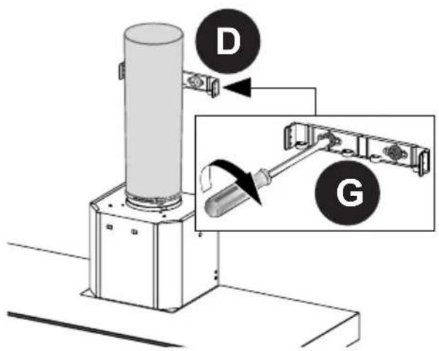
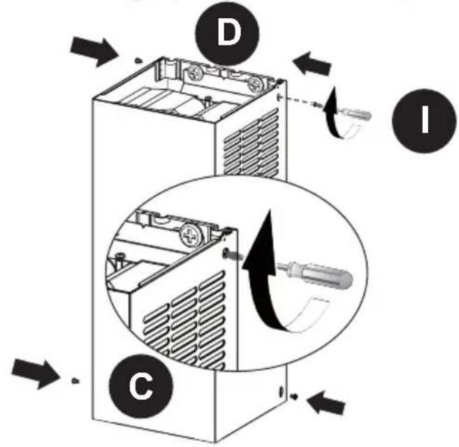
Install the 2 Chimney brackets D to the middle and upper holes and secure with screws G as shown.
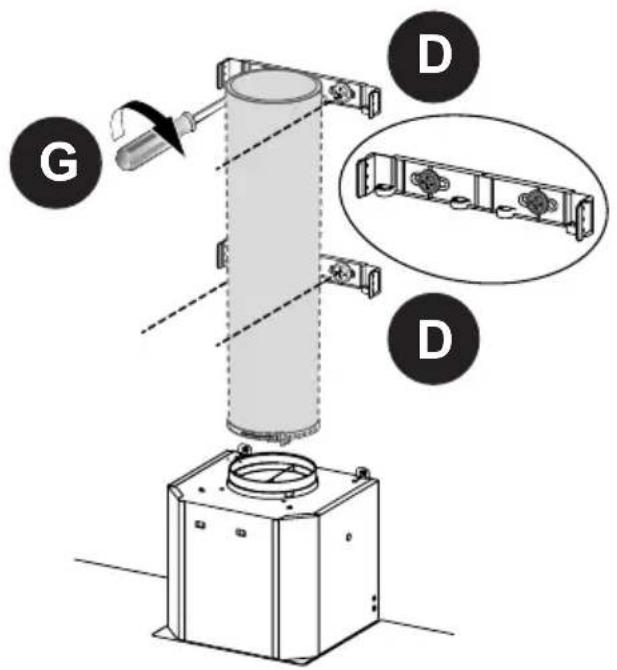
| Phillips Screwdriver |
4 Slightly widen the two sides of the upper chimney Ⓒ and hook them behind the brackets D, making sure that they are well seated.
5 Secure the sides to the brackets by using the 4 screws 1.

| Torx Screwdriver |

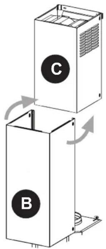
Slightly widen the two sides of the lower chimney hood B and hook them between the upper section and the wall, making sure that they are properly housed.


Install the the lower chimney hood B laterally to the hood body using the 2 screws L supplied.
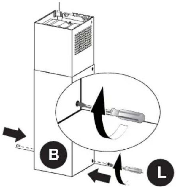
| Torx Screwdriver |

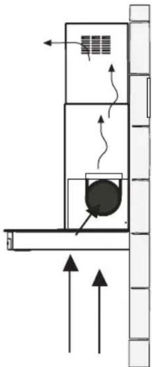
Only for the recirculation version, connect the hood to the Air outlet. Connect 6" metal ductwork to the hood air outlet with foil tape. The 6" ducting needs to be cut to the size of the distance between the air exit and the ductless diverter (see the next page).
natural_image
Technical line drawing of a mechanical assembly with a cylindrical component and a base plate (no text or symbols)
Install the lower Bracket D with two screws G supplied as shown.
| Phillips Screwdriver |
3
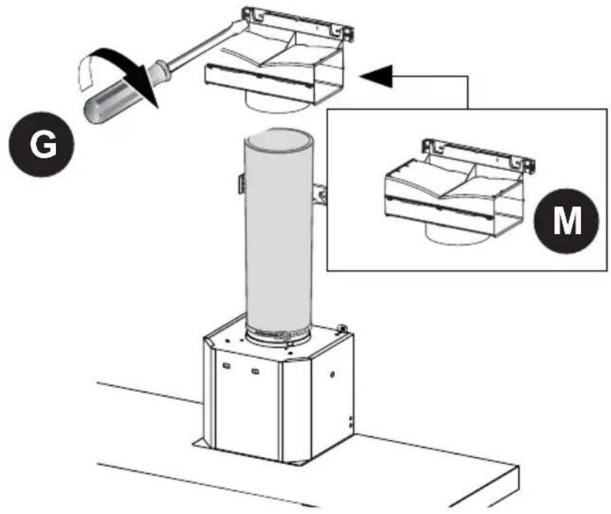
Install the Ductless Diverter M with two screws G supplied as shown.
4
Slightly widen the two sides of the upper chimney Ⓐ and hook them behind the brackets and connect to the Ductless Diverter, making sure that they are well seated.

natural_image
Diagram of a white industrial machine casing with internal components and airflow arrows (no text or symbols)5
Secure the sides to the brackets D by using the 4 screws I.
Torx Screwdriver

6
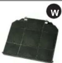
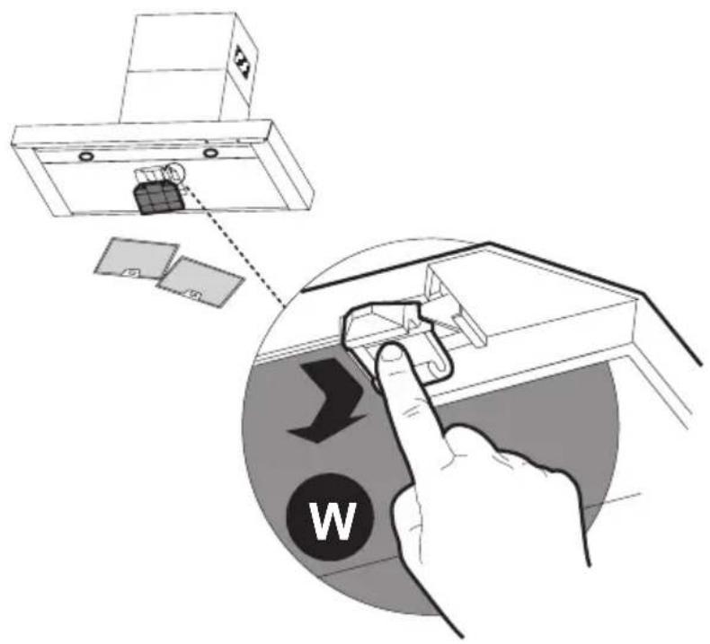
Attach a charcoal filter in the correct position and block it by the attaching hooks as shown. Unlock the hooks (push towards the back of the hood) to remove.
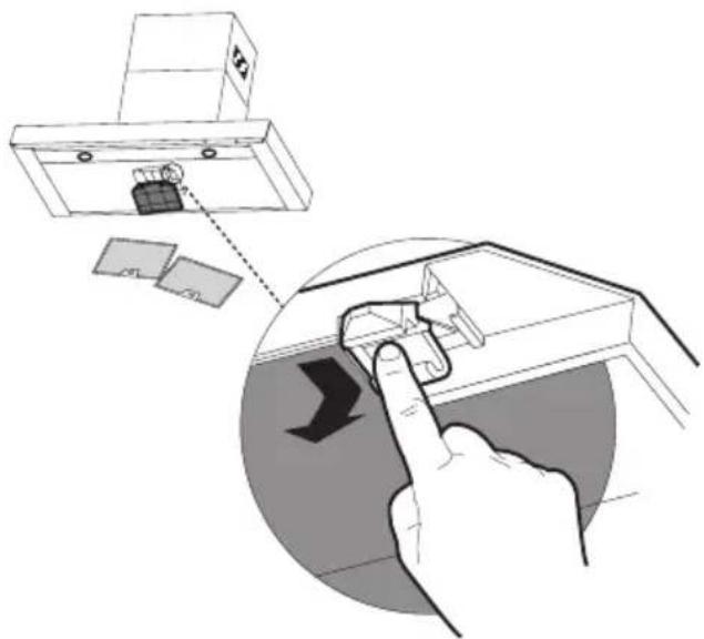
Required Activated Charcoal Filter Accessory - sku # 901497 (purchased separately)
natural_image
Black rectangular solar panel with grid pattern and a circular icon labeled 'W' in the corner (no text or symbols on panel)
Slightly widen the two sides of the lower chimney hood B and hook them between the upper section and the wall, making sure that they are properly housed.

Fix the the lower chimney hood B laterally to the hood body using the 2 screws H supplied.
| Phillips Screwdriver |
GROUNDING INSTRUCTIONS
This appliance must be grounded. In the event of an electrical short circuit, grounding reduces the risk of electric shock by providing an escape wire for the electric current.
This appliance is equipped with a cord with a grounding wire and grounding plug. The plug must be plugged into an outlet that is properly installed and grounded.
WARNING - Improper grounding can result in a risk of electric shock.
Consult a qualified electrician if the grounding instructions are not completely understood, or if doubt exists as to whether the appliance is properly grounded.
Do not use an extension cord. If the power supply cord is too short, have a qualified electrician install an outlet near the appliance.
WARNING - "The supply cord shall be accessible for inspection after installation".
FOR BEST RESULTS
Start the Range Hood several minutes before cooking to develop proper airflow. Allow the Range Hood to operate for several minutes after cooking is complete to clear all smoke and odors from the kitchen.

1
2
3/i

| Button Function | |
 | Fan On/Off Button: Turns the blower On or Off.The fan can be operated by pressing any of the fan setting buttons. |
| Hold down this button for 2 seconds to activate Delay off function which will keep the fan on for 15 minutes and automatically shut off. | |
| ### | Fan Speed Setting: Low Speed |
| ### | Fan Speed Setting: Medium Speed |
| ### | Fan Speed Setting: High Speed/Intensive Speed |
| Hold down the button for 2 seconds to activate the intensive speed, which is timed to run for 10 minutes. At the end of this time it will automatically return to the speed set before.Suitable to deal with maximum levels of cooking fumes. | |
| ### | Light button: On/Off switch for the lights. |
NOTE: If your product has had a CFM adjustment, refer to the CFM adjustment manual for the information. Some motor speeds or functions may be reduced.
Remote control information
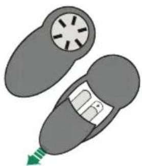
The appliance can be controlled using a remote control powered by a 1.5 V carbon-zinc alkaline batteries of the standard LR03-AAA type (not included).
• Used batteries must be disposed of in the proper manner.
Caution:
- Do not place the remote control near heat sources.
- Do not discard the batteries with normal waste, they must be put into the specific containers.
- Make sure the battery compartment is screwed down flat and is fully tightened.
natural_image
Illustration of a car interior with a circular vent and a green arrow indicating direction (no text or symbols)Remote Control control panel

natural_image
Black handheld electronic device with five metallic buttons (no visible text or symbols)| Motor Motor On/Off. | ||
| - | - Decreases the working speed each time it is pressed. | |
| + | - Increases the working speed each time it is pressed. | |
| i | Intensive Activates/Deactivates Intensive operation. | |
| Delay | Brief pressure: Activates/Deactivates the Delay function: automatic switch-off with a 30' delay. The display shows the operating speed and the dot at the bottom right flashes once a second. | |
| Light | Lights On / Off. | |
Cleaning Exterior surfaces:
Please note, abrasives and scouring agents can scratch range hood finishes and should not be used to clean finished surfaces.
Stainless Steel finish cleaning instructions:
Clean exterior surfaces with a commercially available stainless steel cleaner. Use a soft microfiber cloth and to wipe going with the grain of the stainless steel.
CARING FOR FILTERS
CLEANING METAL GREASE FILTERS
The filters must be cleaned every 2 months of operation, or more frequently for particularly heavy usage, and can be washed in a dishwasher.
- Remove the Filters one at a time, pushing them towards the back of the unit and at the same time pulling downward.
- Wash the Filters without bending them, and leave them to dry completely before replacing. (If the surface of the filter changes colour as time goes by, this will have absolutely no effect on the efficiency of the filter itself.)
- Replace, taking care to ensure that the handle faces forwards.
- No water can be present in filters before installing back in hood.
CAUTION:
Completely dry the Grease Filters after washing.

REPLACING ACTIVATED CHARCOAL FILTER
The filter is not washable and cannot be regenerated, and must be replaced approximately every 4 months of operation, or more frequently for particularly heavy usage.
- Remove the Filters one at a time, pushing them towards the back of the unit and at the same time pulling downward.
- Remove the saturated charcoal filter by releasing the hooks.
• Fit the new filter and fasten it in its correct position. - Replace, taking care to ensure that the handle faces forwards.
- "When used in recirculation mode, to Reduce the Risk of Fire and Shock use only conversion kit Model # 901497.
Please contact the retailer that sold you the product to purchase carbon filters above.
REPLACING BULBS
LED lights must be replaced by authorized service.
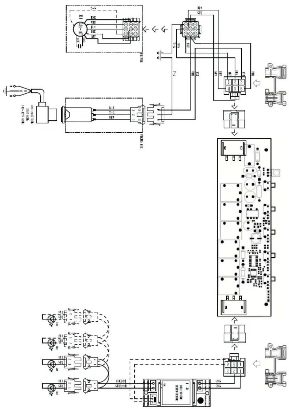
flowchart
graph TD
    A["Power Source"] --> B["Tanistor"]
    B --> C["Relays"]
    C --> D["Grid Panel"]
    D --> E["Output 1"]
    D --> F["Output 2"]
    D --> G["Output 3"]
    D --> H["Output 4"]
    D --> I["Output 5"]
    D --> J["Output 6"]
    D --> K["Output 7"]
    D --> L["Output 8"]
    D --> M["Output 9"]
    D --> N["Output 10"]
    D --> O["Output 11"]
    D --> P["Output 12"]
    D --> Q["Output 13"]
    D --> R["Output 14"]
    D --> S["Output 15"]
    D --> T["Output 16"]
    D --> U["Output 17"]
    D --> V["Output 18"]
    D --> W["Output 19"]
    D --> X["Output 20"]
    D --> Y["Output 21"]
    D --> Z["Output 22"]
    D --> AA["Output 23"]
    D --> AB["Output 24"]
    D --> AC["Output 25"]
    D --> AD["Output 26"]
    D --> AE["Output 27"]
    D --> AF["Output 28"]
    D --> AG["Output 29"]
    D --> AH["Output 30"]
Please kindly register on our web site www.bertazzoni.com to validate your new product warranty and help us to assist you better in case of any inconvenience.
TWO YEAR LIMITED WARRANTY
The warranties provided by Bertazzoni Spa in this statement apply exclusively to Bertazzoni appliances and accessories sold as new products to the original owner by a Bertazzoni authorized distributor, retailer, dealer or service center and installed in the United States and Canada. The warranties provided in this statement are not transferable and have validity from the date of installation.
COVERAGE INFORMATION
Bertazzoni SpA will repair or replace any component part which fails or proves defective due to materials and/or workmanship within 2 years from the date of installation and under conditions of normal residential use. Repair or replacement will be free of charge, including labor at standard rates and shipping expenses. Repair service must be performed by a Bertazzoni Authorized Service
Center during normal working hours.
COSMETIC WARRANTY
Bertazzoni will cover parts showing cosmetic defects in material and workmanship for a period of thirty (30) days from date of installation of the unit. This coverage will include scratches, stains, surface imperfections on stainless steel, paint and porcelain, with the exclusion of slight differences in color due to materials and painting/enamelling technologies.
Exclusions are labor costs, B stock items, out - of - box appliances and display units.
HOW TO OBTAIN SERVICE
To obtain service please contact Bertazzoni Customer Service at the numbers below and make sure to have model number, serial number, and date of purchase ready. This information will be requested by our team and is crucial to speeding up resolution.
UNITED STATES https://us.bertazzoni.com/more/support
Phone: 866-905-0010
CANADA https://ca.bertazzoni.com/more/support
Phone: 800-361-0799
Save proof of original purchase or of original installation to establish warranty period. Copy of the product serial tag is affixed to the back cover of the instruction manual.
WHAT IS NOT COVERED
- The product used in any commercial/business application
- Repair service provided by other than a Bertazzoni authorized service agent.
- Damage or repair service to correct service provided by an unauthorized agency or the use of unauthorized parts.
- Installation not in accordance with local electrical codes or plumbing codes.
- Defects or damage due to improper storage of the product.
- Defects or damage or missing parts on products sold out of the original factory packaging or from displays.
- Service calls or repairs to correct the installation of the product and/or related accessories.
- Service calls to connect, convert or otherwise repair the electrical wiring / gas line / water line to properly use the product.
- Service calls to provide instructions on the use of a Bertazzoni product.
- Repair service due to product usage in manner other than what is normal and customary for home use.
- Replacement of wear and tear parts
- Replacement of glasses and light bulbs if they are claimed to have failed later than 30 days after installation and in no case later than 4 months after date of purchase
- Defects and damages arising from accident, alteration, misuse, abuse, improper installation.
- Defects and damages arising from transportation of the product to the home of the owner.
- Defects and damage arising from external forces beyond the control of Bertazzoni SpA such as fire, flood, earthquakes and other acts of God.
In case the product will be installed in a remote area, where certified trained technicians are not reasonably available, the customer will be responsible for the transportation costs for the delivery of the product to the nearest authorized service center or for the displacement costs of a certified trained technician.
Bertazzoni does not assume any responsibility for incidental or consequential damages.
Some states do not allow the exclusion or limitation of incidental or consequential damages, so the above limitation or exclusion may not apply to you. This warranty gives you specific legal rights and you may also have other rights which may vary from state to state or province to province.
Section Page
CONSIGNES DE SÉCURITÉ IMPORTANTES 34
DIMENSIONS DE LA HOTTE 37
EXIGENCE D'INSTALLATION EN HAUTEUR 38
PIÈCES 39
OUTILS NÉCESSAIRES 41
MÉTHODE D'AÉRATION 42
INSTALLATION 43
CHOIX DE LA MÉTHODE D'AÉRATION 48
RACCORDEZ L'AÉRATION : AÉRATION 49
RACCORDEZ L'AÉRATION : RECIRCULATION 53
BRANCHER LE COURANT DOMESTIQUE 57
UTILISATION DES COMMANDES 58
NETTOYAGE DE L'ACIER INOXYDABLE 60
REEMPLACEMENT DES AMPOULES 61
SCHÉMA DE CÂBLAGE 62
GARANTIE 63
LISEZ ET SAUVEGARDEZ CES INSTRUCTIONS AVANT DE COMMENCER L'INSTALLATION DE CETTE Hotte de cuisine
AVERTISSEMENT : - AFIN DE RÉDUIRE LE RISQUE D'UN INCENDIE DE GRAISSE SUR LA CUISINIÈRE :
MIN. 24" AU-DESSUS D'UN APPAREIL ÉLECTRIQUE MIN. 30" AU-DESSUS DU GAZ
PIÈCES INCLUDES
| REF | PIÈCE | QTÉ | |
| Vis Pozi 3/16" x 1 3/4" | 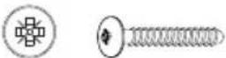 | 6 | |
| Vis Pozi (1/8" x 3/16") |  | 2 | |
| Vis Torx 1/8" x 7/16" |  | 4 | |
| Vis Torx (1/4" x 2 3/4") |  | 2 | |

PIÈCES NÉCESSAIRES (NON INCLUDES)
ACCESSOIRES DISPONIBLES
natural_image
Diagram of a mechanical or architectural component with directional arrows and internal structure (no text or symbols)2
TRAÇAGE DE LIGNES CENTRALES
MIN. 24" AU-DESSUS DE L'ÉLECTRICITÉ/MIN. 30" AU-DESSUS DU GAZ
3
natural_image
Diagram of a structural steel I-beam with a base and top view showing internal components (no text or labels)
| Tournevis Phillips |
AÉRATION

natural_image
Technical diagram of a pipe connection with directional arrows indicating flow or movement (no text or symbols)Aller à Pg.49
RECIRCULATION
natural_image
Diagram of a building interior with ventilation and airflow indicators (no text or symbols)Aller à la Pg.53

natural_image
Simple 3D diagram showing a cylinder above a sphere on a base, with no text or symbols present.
| Tournevis Phillips |

| Tournevis Torx |

natural_image
Technical line drawing of a mechanical assembly with a cylindrical component and a square housing (no text or symbols)
| Tournevis Phillips |


natural_image
Diagram of a box with labeled components and airflow arrows, no readable text or symbols present.5
natural_image
Black rectangular solar panel with grid pattern and a circular label containing the letter 'W' (no text or symbols on the panel itself)
| Tournevis Phillips |
INSTRUCTIONS DE MISE À LA TERRE
natural_image
Illustration of a device with a circular component and a green arrow pointing to it (no text or symbols)natural_image
Black handheld electronic device with five metallic buttons (no visible text or symbols)REPLACEMENT FILTRE À CHARBONS ACTIFS
REPLACEMENT DES AMPOULES
https://us.bertazzoni.com/more/support
Phone: 866-905-0010
CANADA
https://ca.bertazzoni.com/more/support
Phone: 800-361-0799


- Section Page
- READ AND SAVE THESE INSTRUCTIONS BEFORE YOU START INSTALLING THIS Range Hood
- ALL WALL AND FLOOR OPENINGS WHERE THE Range Hood IS INSTALLED MUST BE SEALED.
- VENTING REQUIREMENTS
- Cold Weather installations
- WARNING
- ELECTRICAL REQUIREMENTS
- State of California Proposition 65 Warning (US only)
- RECIRCULATING
- DRAW CENTER LINES
- 3
- GROUNDING INSTRUCTIONS
- FOR BEST RESULTS
- Remote control information
- Caution:
- Cleaning Exterior surfaces:
- Stainless Steel finish cleaning instructions:
- CARING FOR FILTERS
- CLEANING METAL GREASE FILTERS
- REPLACING ACTIVATED CHARCOAL FILTER
- REPLACING BULBS
- TWO YEAR LIMITED WARRANTY
- COVERAGE INFORMATION
- COSMETIC WARRANTY
- HOW TO OBTAIN SERVICE
- WHAT IS NOT COVERED
- LISEZ ET SAUVEGARDEZ CES INSTRUCTIONS AVANT DE COMMENCER L'INSTALLATION DE CETTE Hotte de cuisine
- 2
- TRAÇAGE DE LIGNES CENTRALES
- INSTRUCTIONS DE MISE À LA TERRE
- REPLACEMENT FILTRE À CHARBONS ACTIFS
- REPLACEMENT DES AMPOULES
Brand : BERTAZZONI
Model : KT48XT
Category : Range hood