
KIN30XT - Range hood BERTAZZONI - Free user manual and instructions
Find the device manual for free KIN30XT BERTAZZONI in PDF.
| Product Type | Built-in Hood |
| Brand | Bertazzoni |
| Model | KIN30XT |
| Electrical Supply | 120 V, 60 Hz, 15 A (dedicated circuit) |
| Number of Speeds | 3 speeds + intensive speed (6 minutes) |
| Lighting | LED GU10 (integrated ballast) |
| Delayed Shut-off Function | Yes, 15 minutes |
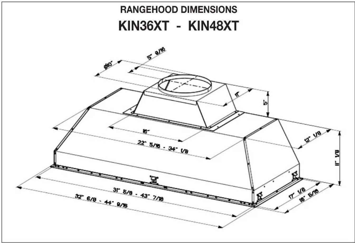
| Duct Diameter | 10 inches (25.4 cm) round |
| Grease Filters | Stainless steel, dishwasher safe |
| Charcoal Filters (recirculation option) | Replace every 4 months (SKU #901531 or #901532) |
| Minimum Cabinet Opening Height | 16 inches (40.6 cm) |
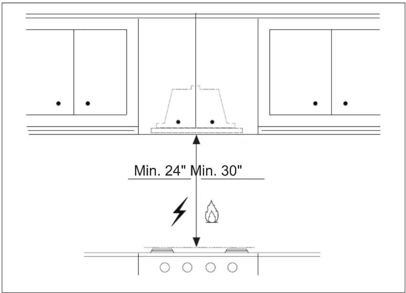
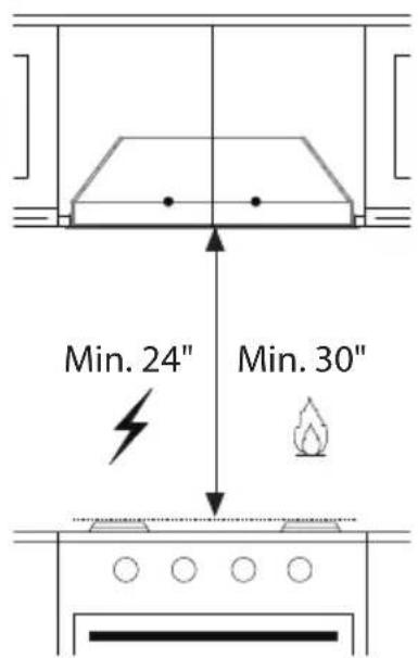
| Minimum Hood-Cooking Surface Distance | 24 in (61 cm) for electric, 30 in (76.2 cm) for gas |
| Installation Type | Built-in, external evacuation or recirculation |
| Material | Stainless steel |
| Warranty | See Bertazzoni website |
Frequently Asked Questions - KIN30XT BERTAZZONI
User questions about KIN30XT BERTAZZONI
0 question about this device. Answer the ones you know or ask your own.
Ask a new question about this device
Download the instructions for your Range hood in PDF format for free! Find your manual KIN30XT - BERTAZZONI and take your electronic device back in hand. On this page are published all the documents necessary for the use of your device. KIN30XT by BERTAZZONI.
USER MANUAL KIN30XT BERTAZZONI
INSTALLATION AND USER MANUAL
LINER/INSERT HOODS

BERTAZZONI
INSTRUCTIONS D'INSTALLATION ET D'UTILISATION
HOTTES À FILTRE/ENCASTRABLE


KIN..XT
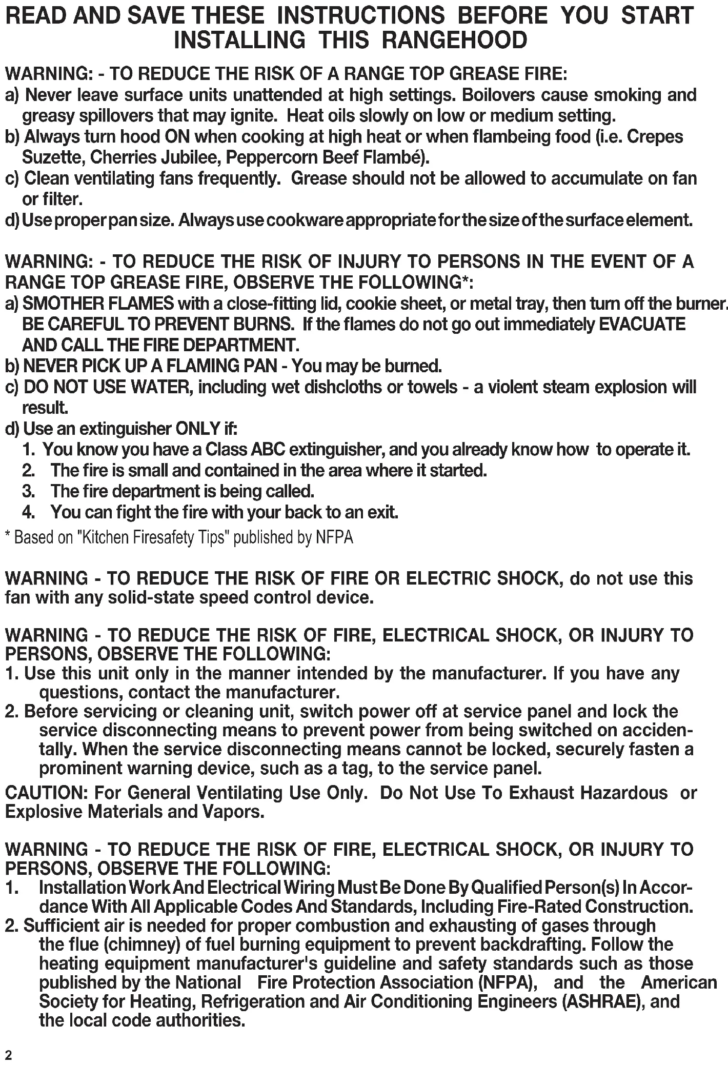
READ AND SAVE THESE INSTRUCTIONS BEFORE YOU START INSTALLING THIS RANGEHOOD
WARNING: - TO REDUCE THE RISK OF A RANGE TOP GREASE FIRE:
a) Never leave surface units unattended at high settings. Boilovers cause smoking and greasy spillovers that may ignite. Heat oils slowly on low or medium setting.
b) Always turn hood ON when cooking at high heat or when flaming food (i.e. Crepes Suzette, Cherries Jubilee, Peppercorn Beef Flambé).
c) Clean ventilating fans frequently. Grease should not be allowed to accumulate on fan or filter.
d) Use proper pan size. Always use cookware appropriate for the size of the surface element.
WARNING: - TO REDUCE THE RISK OF INJURY TO PERSONS IN THE EVENT OF A RANGE TOP GREASE FIRE, OBSERVE THE FOLLOWING*:
a) SMOTHER FLAMES with a close-fitting lid, cookie sheet, or metal tray, then turn off the burner. BE CAREFUL TO PREVENT BURNS. If the flames do not go out immediately EVACUATE AND CALL THE FIRE DEPARTMENT.
b) NEVER PICK UP A FLAMING PAN - You may be burned.
c) DO NOT USE WATER, including wet dishcloths or towels - a violent steam explosion will result.
d) Use an extinguisher ONLY if:
- You know you have a Class ABC extinguisher, and you already know how to operate it.
- The fire is small and contained in the area where it started.
- The fire department is being called.
-
You can fight the fire with your back to an exit.
-
Based on "Kitchen Firesafety Tips" published by NFPA
WARNING - TO REDUCE THE RISK OF FIRE OR ELECTRIC SHOCK, do not use this fan with any solid-state speed control device.
WARNING - TO REDUCE THE RISK OF FIRE, ELECTRICAL SHOCK, OR INJURY TO PERSONS, OBSERVE THE FOLLOWING:
- Use this unit only in the manner intended by the manufacturer. If you have any questions, contact the manufacturer.
- Before servicing or cleaning unit, switch power off at service panel and lock the service disconnecting means to prevent power from being switched on accidentally. When the service disconnecting means cannot be locked, securely fasten a prominent warning device, such as a tag, to the service panel.
CAUTION: For General Ventilating Use Only. Do Not Use To Exhaust Hazardous or Explosive Materials and Vapors.
WARNING - TO REDUCE THE RISK OF FIRE, ELECTRICAL SHOCK, OR INJURY TO PERSONS, OBSERVE THE FOLLOWING:
- Installation Work And Electrical Wiring Must Be Done By Qualified Person(s) In Accordance With All Applicable Codes And Standards, Including Fire-Rated Construction.
-
Sufficient air is needed for proper combustion and exhausting of gases through the flue (chimney) of fuel burning equipment to prevent backdrafting. Follow the heating equipment manufacturer's guideline and safety standards such as those published by the National Fire Protection Association (NFPA), and the American Society for Heating, Refrigeration and Air Conditioning Engineers (ASHRAE), and the local code authorities.
-
When cutting or drilling into wall or ceiling, do not damage electrical wiring and other hidden utilities.
- Ducted fans must always be vented to the outdoors.
ALL WALL AND FLOOR OPENINGS WHERE THE RANGEHOOD IS INSTALLED MUST BE SEALED. This rangehood requires at least 24" of clearance between the bottom of the rangehood and the cooking surface or countertop. This hood has been approved by UL at this distance from the cooktop.
This minimum clearance may be higher depending on local building codes. For gas cooktops and combination ranges, a minimum of 30" is recommended and may be required.
Overhead cabinets on both sides of this unit must be a minimum of 18" above the cooking surface or countertop. Consult the cooktop or range installation instructions given by the manufacturer before making any cutouts.
MOBILE HOME INSTALLATION The installation of this rangehood must conform to the Manufactured Home Construction and Safety Standards, Title 24 CFR, Part 3280 (formerly Federal Standard for Mobile Home Construction and Safety, Title 24, HUD, Part 280). See Electrical Requirements.
VENTING REQUIREMENTS
Determine which venting method is best for your application. Ductwork can extend either through the wall or the roof.
The length of the ductwork and the number of elbows should be kept to a minimum to provide efficient performance. The size of the ductwork should be uniform. Do not install two elbows together. Use duct tape to seal all joints in the ductwork system. Use caulking to seal exterior wall or floor opening around the cap.
Flexible ductwork is not recommended. Flexible ductwork creates back pressure and air turbulence that greatly reduces performance.
Make sure there is proper clearance within the wall or floor for exhaust duct before making cutouts. Do not cut a joist or stud unless absolutely necessary. If a joist or stud must be cut, then a supporting frame must be constructed.
WARNING - To Reduce The Risk Of Fire, Use Only Metal Ductwork.
CAUTION - To reduce risk of fire and to properly exhaust air, be sure to duct air outside - Do not vent exhaust air into spaces within walls or ceilings or into attics, crawl spaces, or garages.
Cold Weather installations
An additional back draft damper should be installed to minimize backward cold air flow and a nonmetallic thermal break should be installed to minimize conduction of outside temperatures as part of the vent system. The damper should be on the cold air side of the thermal break. The break should be as close as possible to where the vent system enters the heated portion of the house.

WARNING
- Venting system MUST terminate outside the home.
- DO NOT terminate the ductwork in an attic or other enclosed space.
DO NOT use 4" laundry-type wall caps. - Flexible-type ductwork is not recommended.
- DO NOT obstruct the flow of combustion and ventilation air.
- Failure to follow venting requirements may result in a fire.
ELECTRICAL REQUIREMENTS
A 120 volt, 60Hz AC-only electrical supply is required on a separate 15 amp fused circuit. A time-delay fuse or circuit breaker is recommended. The fuse must be sized per local codes in accordance with the electrical rating of this unit as specified on the serial/rating plate located inside the unit near the field wiring compartment.

WARNING
- Electrical ground is required on this rangehood.
- If cold water pipe is interrupted by plastic, nonmetallic gaskets or other materials, DO NOT use for grounding.
DO NOT ground to a gas pipe. - DO NOT have a fuse in the neutral or grounding circuit. A fuse in the neutral or grounding circuit could result in electrical shock.
- Check with a qualified electrician if you are in doubt as to whether the rangehood is properly grounded.
- Failure to follow electrical requirements may result in a fire.
State of California Proposition 65 Warning (US only)
WARNING
This product contains chemicals known to the State of California to cause cancer and birth defects or other reproductive harm.
For more information go to www.P65Warnings.ca.gov
MAIN PARTS
Components
Ref. Qty. Product Components
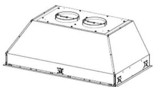
1 1 Hood Body, complete with: Controls, Light, Filters, Blower.
2 1 Power cord
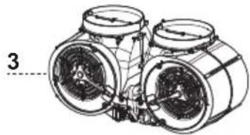
3 1 Blower
41Grease rail
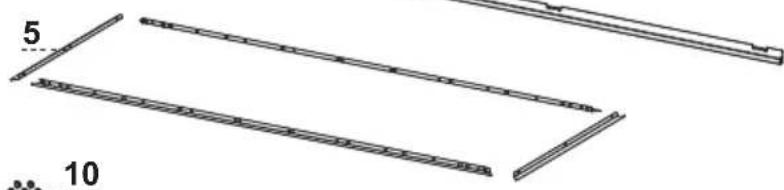
5 4 Left/right trim
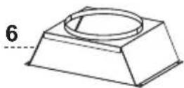
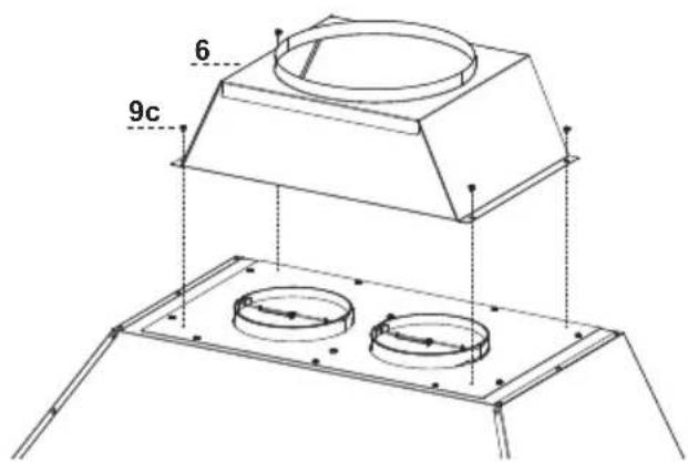
6 1 Duct transition
7 6 Filter knobs (36" version)
7 8 Filter knobs (48" version)
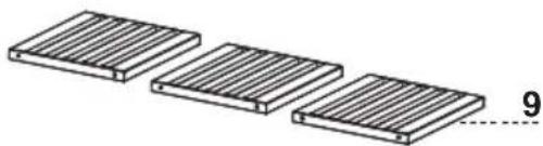
9 3 Grease filters (36" version)
9 4 Grease filters (48" version)
10 5 Stopper
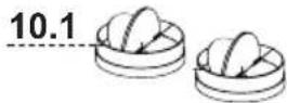
10.1 2 Damper 57/8"
Ref. Qty. Installation Components
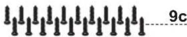
9c 22 Install screws (1/8"x1/4") (36" version)
9c 26 Install screws (1/8"x1/4") (48" version)
9c 4 Install screws (1/8"x1/4")
9e 6 Grease filters screws 5 / 32'' x 5 / 16'' (36" version)
9e 8 Grease filters screws 5 / 32'' x 5 / 16'' (48" version)
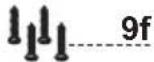
9f 4 Screws 3 / 16^ 3 / 8^
Qty. Documentation
1 Instruction Manual


Parts needed
- 10" Round Metal ductwork.
Available Accessories
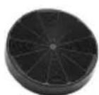
Charcoal Filter kit sku #901531
Durable charcoal filter kit sku #901532
Remote Control Accessory sku #901575
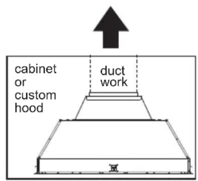
RECIRCULATING INSTALLATIONS
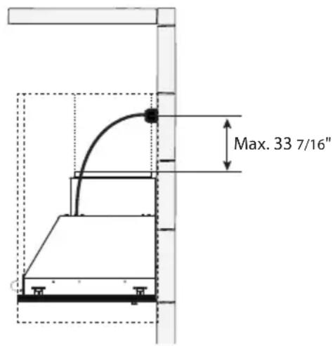
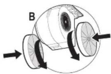
IT IS HIGHLY RECOMMENDED THAT PROFESSIONAL STYLE COOKING ALWAYS BE VENTED TO THE OUTSIDE. For recirculating installations (Figure 1), Charcoal Filters are necessary. Remove all grease filters and set aside. Attach one charcoal filter to each end of the blower. Each charcoal filter attaches to the grid on the side of the blower. Rotate the filter clockwise to install and counterclockwise to remove (Figure 1A). Replace all grease filters. Recirculating installations also require some duct work to divert the air out of the top or face or side of the cabinet or custom hood or out of the side / face of the soffit and back into the kitchen. Install at least 15^ of vertical run of metal duct (Figure 1) at the air outlet. Run the duct vertically and secure it at the relevant opening previously cut out at the top or side of the cabinet or soffit. A metal duct cover grille is also recommended. The duct work must not terminate inside the cabinet or custom hood.
ceiling
ceiling

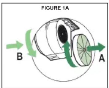
FIGURE 1
FOR ALL INSTALLATIONS REMOVE ALL WHITE PLASTIC PROTECTIVE COVERING FROM HOOD, SIDE RAILS, TRIM, GREASE RAILS AND GREASE FILTERS.
INSTALLATION
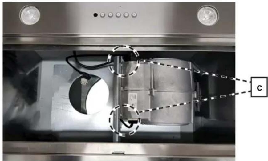
- Install the 1^st motor into the sides of the blower bracket using the 2 screws supplied (9f) in position C.
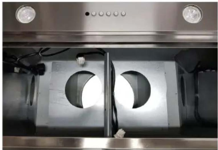
- Plug the 9 way connector on the blower in the position D.
- Plug the power cable on the blower in the position E.


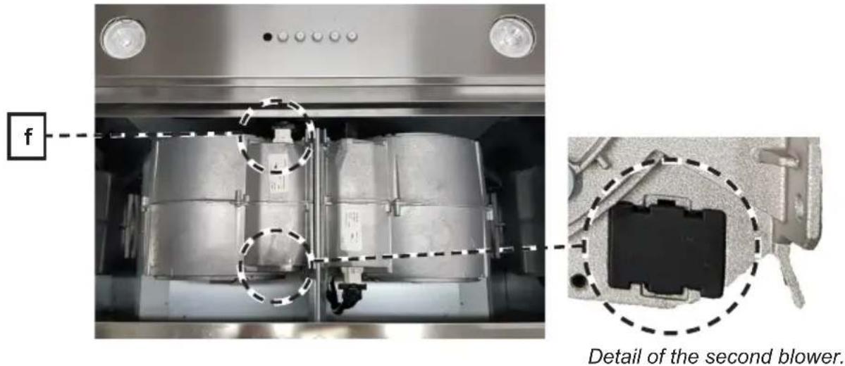
- Install the 2^nd motor into the sides of the blower bracket using the 2 screws supplied (9f) in the position C.

- Plug the 9 way connector on the second blower in position F.
- Connect the damper (10.1) to the motors. Install the 10^ duct transition (6) and install with four screws (9c).

- Remove the white plastic covering and install the side trim piece (5) to the outside of the hood using part 9c screws, see the side trim installation in.

- Follow step 1-2 to connect ducting, and test the electrical connection.
Installation Instructions
1a
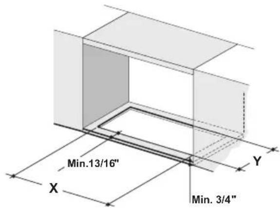
Cut out the opening in the underside of the cabinet as shown in Figure 1a.
| Model # XY | ||
| KIN36XT 31-7/8" 17-3/8" | ||
| KIN48XT 43-11/16" 17-3/8" |
1b

OK!
Two people may be required for installation.
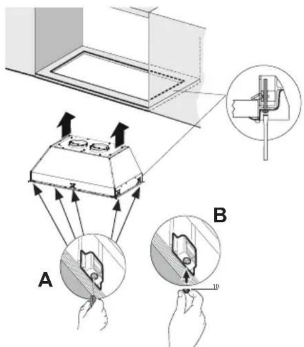
It is recommend that the Insert Hood is supported by a 3/4'' wood base to insure Side Mount Clip alignment.
Minimum cabinet opening height-16". However height may vary to allow for ducting. Install the Insert Hood into the cabinet opening, and fully engage the four spring-loaded Side Mount Clips onto the cabinet wood base.
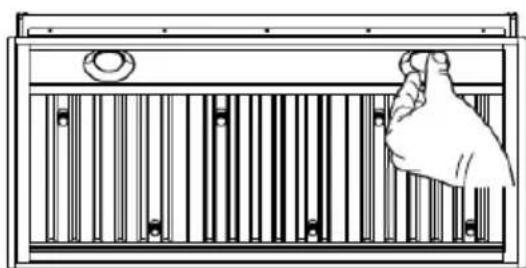
Next from underneath the Insert as shown in Figure A, locate the screw in each of the Side Mount Clips.
To lock the Insert Hood into position, tighten the screw for each of four Side Mount Clips. Next from underneath the Insert Hood Place the four plastic stoppers (10) as shown in Figure B.
2 For Non-Ducted Recirculation Option

Attach each charcoal filter to the black grid on each side of the blower. Press the charcoal filter tightly to the black grid on the blower side and rotate the filter clockwise (towards the front of the insert hood) until it locks into place. Turn counterclockwise (towards the back of the insert hood) to remove.
Required Charcoal Filter kit sku #901531
Durable charcoal filter kit sku #901532
(purchased separately)

Hook the Grease rail (4) positioning it inside the hood. Is possible wash and reposition inside the hood.
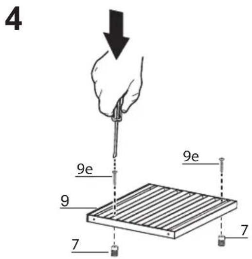
Baffle Filter
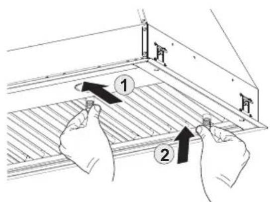
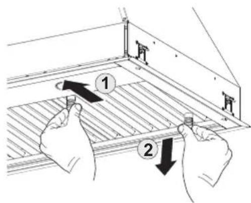
Before installing the filters (9), tighten the 2 knobs (7) with 2 screws (9e). Use two hands to insert and remove the filters.
5
ELECTRICAL INSTALLATION WITH CONNECTION CABLE
GROUNDING INSTRUCTIONS This appliance must be grounded. In the event of an electrical short circuit, grounding reduces the risk of electric shock by providing an escape wire for the electric current. This appliance is equipped with a cord having a grounding wire with a grounding plug. The plug must be plugged into an outlet that is properly installed and grounded.
WARNING - Improper grounding can result in a risk of electric shock.
Consult a qualified electrician if the grounding instructions are not completely understood, or if doubt exists as to whether the appliance is properly grounded.
Do not use an extension cord. If the power supply cord is too short, have a qualified electrician install an outlet near the appliance.
WARNING - "The supply cord shall be accessible for inspection after installation".
USE AND CARE INFORMATION
For Best Results
Start the rangehood several minutes before cooking to develop proper airflow. Allow the rangehood to operate for several minutes after cooking is complete to clear all smoke and odors from the kitchen.

T1. Fan off button: turn the blower Off. The fan can be operated by pressing any of the fan setting buttons. Hold down this button for 2 seconds to activate Delay off function which will keep the fan on for 15 minutes and automatically shut off.
T2. Fan settings buttons: Low speed.
T3. Fan settings buttons: Medium speed.
T4. Fan settings buttons: High speed / Intensive speed.
Hold down the button for 2 seconds to activate the intensive speed, which is timed to run for 6 minutes. At the end of this time it will automatically return to the speed set before. Suitable to deal with maximum levels of cooking fumes.
L. Light button: On/Off switch for the lights.
NOTE: If your product has had a CFM adjustment, refer to the CFM adjustment manual for the information. Some motor speeds or functions may be reduced.
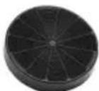
Replacing Activated Charcoal Filter
The Activated Charcoal Filters are not washable and cannot be regenerated, and should be replaced approximately every 4 months of operation, or more frequently with heavy usage.
- Remove the charcoal filter by rotating it clockwise ( backwards) until it unlocks from the motor housing and pull off sideways.
- To re-insert each charcoal filter, place up against the side of the blower and push it inward. Then turn the charcoal filter clockwise (forward) until it fits into place.
Caution: "When used in recirculation mode, to Reduce the Risk of Fire and Shock use only conversion kit Model Charcoal Filter kit sku #901531; Durable charcoal filter kit sku #901532"
Please contact the retailer that sold you the product to purchase carbon filters above.
Cleaning
The stainless steel grease filters and grease rail should be cleaned frequently in hot detergent solution or washed in the dishwasher. Clean exterior surfaces with a commercially available stainless steel cleaner. Abrasives and scouring agents can scratch stainless steel finishes and should not be used to clean finished surfaces.
Make sure the grease filters are completely dry with no water present before re-installing into hood.
Grease rail and Grease Filter Installation / Removal.
Remove the plastic from the filter, the knobs need to be installed onto the filter with 2 screws to each filter.
Install the grease rail into the back of the hood, into the slots on the inside floor of the rear of the hood. The Grease filters should be installed before operating the rangehood. To install the filters, use the two knobs to hold the filter and insert the filter into the front edge of the hood with the knobs facing out into the spring loaded slot. Install the other end of the filter above the grease rail in the back of the hood.

Lighting unit
- Replace the lamp with a new one of the same type, making sure that you insert the two pins properly into the housings on the lamp holder.

Gu10 self-ballasted led lamps - listed in accordance with ul 1993/nmx-j-578/1-ance/csa c22.2 No. 1993

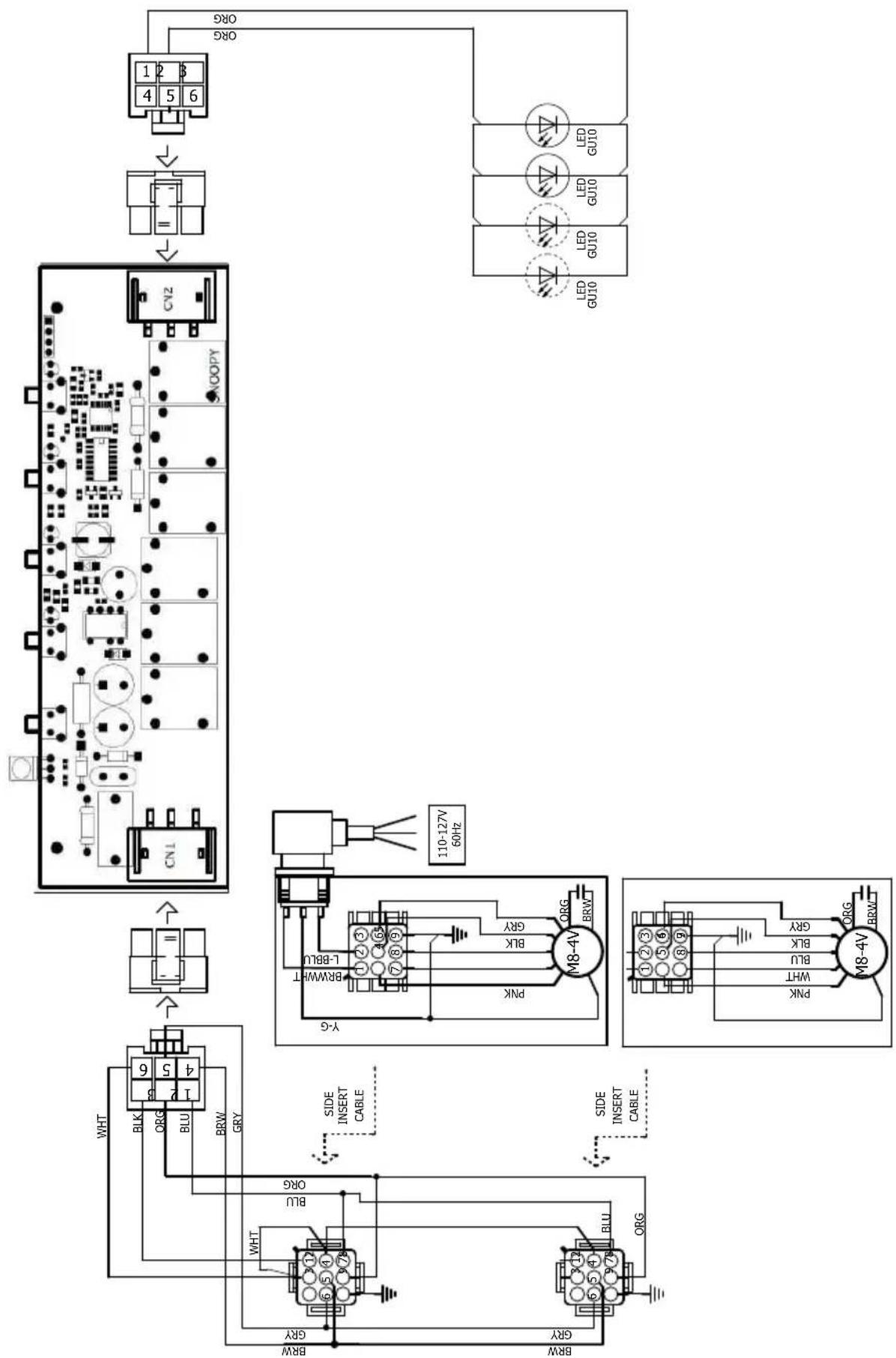
Wiring Diagram
For any warranty information and service request, contact us:

In USA: https://us.bertazzoni.com/more/support
In Canada: https://ca.bertazzoni.com/more/support
VEUILLEZ LIRE ET CONSERVER LA PRESENTE NOTICE AVANT DE COMMENCER L'INSTALLATION DE LA HOTTE DE CUISINE
AVERTISSEMENT : POUR RÉDUIRE LE RISQUE D'UN FEU DE GRAISSE SUR LA TABLE DE CUISSON :
Available Accessories
Kit matériel a charbon sku #901531
INSTALLATIONS A RECIRCULATION
| Modèle # XY | ||
| KIN36XT 31-7/8" 17-3" | 8" | |
| KIN48XT 43-11/16" 17 | -3/8" |

1b

OK!


- READ AND SAVE THESE INSTRUCTIONS BEFORE YOU START INSTALLING THIS RANGEHOOD
- VENTING REQUIREMENTS
- Cold Weather installations
- WARNING
- ELECTRICAL REQUIREMENTS
- State of California Proposition 65 Warning (US only)
- MAIN PARTS
- Components
- Ref. Qty. Product Components
- Ref. Qty. Installation Components
- Qty. Documentation
- Parts needed
- Available Accessories
- RECIRCULATING INSTALLATIONS
- INSTALLATION
- Installation Instructions
- For Non-Ducted Recirculation Option
- Baffle Filter
- 5
- ELECTRICAL INSTALLATION WITH CONNECTION CABLE
- USE AND CARE INFORMATION
- For Best Results
- Replacing Activated Charcoal Filter
- Cleaning
- Lighting unit
- VEUILLEZ LIRE ET CONSERVER LA PRESENTE NOTICE AVANT DE COMMENCER L'INSTALLATION DE LA HOTTE DE CUISINE
- INSTALLATIONS A RECIRCULATION
Brand : BERTAZZONI
Model : KIN30XT
Category : Range hood