
AK965L - Heating Air King - Free user manual and instructions
Find the device manual for free AK965L Air King in PDF.
| Product Type | Exhaust Fan with Heater |
| Brand | Air King |
| Model | AK965L |
| Rated Voltage | 120 V, 60 Hz |
| Rated Current | 15.65 A |
| Recommended Circuit | 20 A, dedicated |
| Functions | Ventilation, heating, main light, night light |
| Main Light | A19 incandescent bulb, max 100 W (not included) |
| Night Light | Candelabra bulb, max 7 W (not included) |
| Installation | Ceiling or wall, min. clearance 17.78 cm |
| Duct | Exhaust to outside, rigid duct recommended |
| Control | By wall switches (4 functions) |
| Motor Protection | Built-in thermal protection |
| Thermal Fuse | Yes, in heating wiring |
| Maintenance | Clean grille and fan every 6 months |
| Motor Maintenance | Permanently lubricated, do not add lubricant |
| Warranty | 1 year, limited |
| Customer Service | 1-800-465-7300, Mon-Fri 8am-4pm EST |
Frequently Asked Questions - AK965L Air King
User questions about AK965L Air King
0 question about this device. Answer the ones you know or ask your own.
Ask a new question about this device
Download the instructions for your Heating in PDF format for free! Find your manual AK965L - Air King and take your electronic device back in hand. On this page are published all the documents necessary for the use of your device. AK965L by Air King.
USER MANUAL AK965L Air King
IMPORTANT INSTRUCTIONS - OPERATING MANUAL
Models: AK-965L

Exhaust Fan with Heater

READ AND SAVE THESE INSTRUCTIONS
READ CAREFULLY BEFORE ATTEMPTING TO ASSEMBLE, INSTALL, OPERATE OR MAINTAIN THE PRODUCT DESCRIBED. PROTECT YOURSELF AND OTHERS BY OBSERVING ALL SAFETY INFORMATION. FAILURE TO COMPLY WITH INSTRUCTIONS COULD RESULT IN PERSONAL INJURY AND/OR PROPERTY DAMAGE!

RETAIN INSTRUCTIONS FOR FUTURE REFERENCE.
GENERAL SAFETY INFORMATION
When using electrical appliances, basic precautions should always be followed to reduce the risk of fire, electric shock and injury to person, including the following:
WARNING: TO REDUCE THE RISK OF FIRE, ELECTRIC SHOCK AND INJURY TO PERSON, OBSERVE THE FOLLOWING:
a) Use this heater only as described in this manual. Any other use not recommended by the manufacturer may cause fire, electric shock, or injury to persons.
b) Operate heater only when grille is installed.
c) Before servicing or cleaning the unit, switch power off at service panel and lock the service disconnecting means to prevent power from being switched on accidentally. When the service disconnecting means cannot be locked, securely fasten a prominent warning device, such as a tag, to the service panel.
d) Do not operate any heater after it malfunctions. Disconnect power at service panel and have heater inspected by a reputable electrician before reusing.
e) Do not use outdoors.
f) Do not insert or allow foreign objects to enter any ventilation or exhaust opening as this may cause and electric shock or fire, or damage the heater.
g) To prevent a possible fire, do not block air intakes or exhaust in any manner.
WARNING: TO REDUCE THE RISK OF FIRE, ELECTRIC SHOCK AND INJURY TO PERSON, OBSERVE THE FOLLOWING:
a) Installation work and electrical wiring must be done by qualified person(s) in accordance with all applicable codes and standards, including fire-related construction.
b) For supply connections, use wires suitable for at least 75irc C ( 167irc F).
c) Use copper wire only.
d) Sufficient air is needed for proper combustion and exhausting of gases through the flue (chimney) of fuel burning equipment to prevent back drafting. Follow the heating equipment manufacturer's guideline and safety standards such as those published by the National Fire Protection Association (NFPA) and the American Society for Heating, Refrigeration, and Air Conditioning Engineers (ASHRAE), and the local code authorities.
e) When cutting or drilling into wall or ceiling, do not damage electrical wiring and other hidden utilities.
CAUTION: FOR GENERAL VENTILATING USE ONLY. DO NOT USE TO EXHAUST HAZARDOUS OR EXPLOSIVE MATERIALS AND VAPORS.
f) A heater has hot and arcing or sparking parts inside. Do not use in areas where gasoline, paint, or flammable vapors or liquids are used or stored.
g) Ducted fans must always be vented to the outdoors.
h) This unit must be grounded.
i) To avoid motor bearing damage and noisy and/or unbalanced impellers, keep drywall spray, construction dust, etc. off power unit.
j) This heater is hot when in use. To avoid burns, do not let bare skin touch hot surfaces.
k) Extreme caution is necessary when any heater is used by or near children or invalids and whenever the heater is left operating and unattended.
IMPORTANT INSTRUCTIONS: Read all instructions before installing or using exhaust fan.
WARNING: TO REDUCE THE RISK OF FIRE, ELECTRIC SHOCK, DO NOT USE THIS FAN WITH ANY SOLID-STATE SPEED CONTROL DEVICE.
WARNING: DO NOT INSTALL OVER A TUB OR MOUNT IN A SHOWER STALL ENCLOSURE.

WARNING: DO NOT USE IN KITCHENS.
WARNING: THIS UNIT IS DESIGNED AND TESTED TO BE A SUPPLEMENTAL HEATER FOR USE WITH A TIMER OR A INTENDED TO BE USED AS THE PRIMARY SOURCE OF HEAT BY A THERMOSTAT.
Motor is thermally protected.
Electrical Ratings: AK965L - 120V, 60Hz., 15.65A AKF965 - 120V, 60Hz., 15.20A
INSTALLATION INSTRUCTIONS
CAUTION: MAKE SURE POWER IS SWITCHED OFF AT SERVICE PANEL BEFORE STARTING INSTALLATION.
WARNING: TO REDUCE THE RISK OF FIRE, DO NOT STORE OR USE GASOLINE OR OTHER FLAMMABLE VAPORS AND LIQUIDS IN THE VICINITY OF THE HEATER.
SECTION 1
Preparing the Exhaust Fan
- Unpack fan from the carton and confirm that all pieces are present. In addition to the exhaust fan you should have:
1 - Grill with Light Lens
4 - Mounting Rails
2 - 2 Function Switches
1 - Quad Wall Plate
1 - Instruction/Safety Sheet
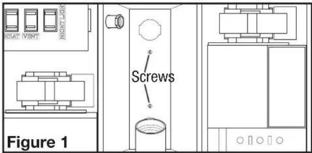
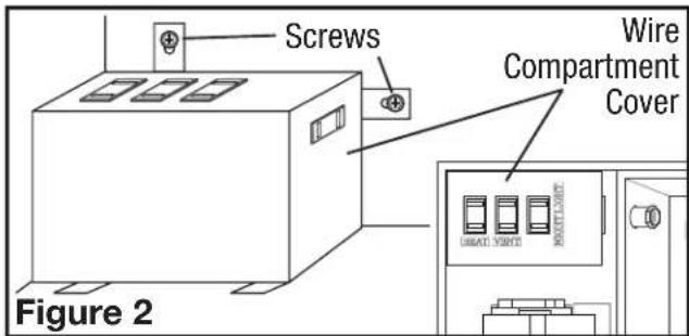
- Remove the two machine screws holding the light reflector in place. Keep the reflector and screws in the carton until needed so they do not get damaged or lost (Figure 1).
- Remove the wire compartment cover by loosening the two screws holding the cover in place (Figure 2).
WARNING: DO NOT INSTALL OVER A TUB OR MOUNT IN A SHOWER STALL ENCLOSURE.
- Choose the location for your unit. To ensure the best air and sound performance, it is recommended that the length of ducting and the number of elbows be kept to a
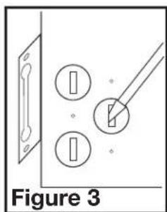
minimum, and that insulated hard ducting be used. Larger duct sizes will reduce noise and airflow restrictions. This fan will require at least 7" of clearance in the ceiling, and will mount through drywall up to 3/4" thick. The fan can be mounted directly to the joist using the mounting tabs on the side of the housing or between 16" on center joists using the 4 provided mounting rails.
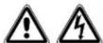
- Remove the electrical knockouts using a straight-blade screw driver (Figure 3).
SECTION 2
New Construction
- Mounting Rail Installation: Install the rails on the housing and position the housing next to the joist. Line up housing so it will be flush with the finished ceiling. Secure the ends of the rails with screws or nails (not included) to the joists and slide housing into final position (Figure 4).
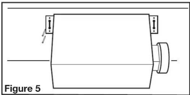
1a. Mounting Tab Installation: Line up housing so that it will be flush with the finished ceiling. Position the fan so that the tabs rest flat against the joist and secure with screws or nails (not provided) to ensure proper installation (Figure 5).
natural_image
Technical line drawing of a mechanical component with mounting holes and a central shaft (no text or symbols)SECTION 3
Existing Construction
- Mounting Rail Installation: Set housing in position between the joist and trace an outline onto the ceiling material (Figure 6). Set housing aside and cut opening, being careful not to cut or damage any electrical or other hidden utilities. Install the rails on the housing and position the housing in the previously cut hole so that it is flush with the finished ceiling. Secure the ends of the rails to the joists with screws or nails (not provided) to ensure proper installation (Figure 4).

natural_image
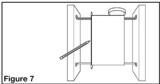
Technical line drawing of a mechanical assembly with a pencil inserted, labeled Figure 6 (no text or symbols on the diagram itself)1a. Mounting Tab Installation: Position housing against the joist and trace an outline of the housing onto the ceiling material (Figure 7). Set housing aside and cut opening, being careful not to cut or damage any electrical or other hidden utilities. Place housing next to the joist and insure that it is flush with the finished ceiling. Secure with screws or nails (not provided) to the joists (Figure 5).
natural_image
Technical line drawing of a mechanical assembly with a tool and bracket (no text or symbols)SECTION 4
Ducting

CAUTION: ALL DUCTING MUST COMPLY WITH LOCAL AND NATIONAL BUILDING CODES.
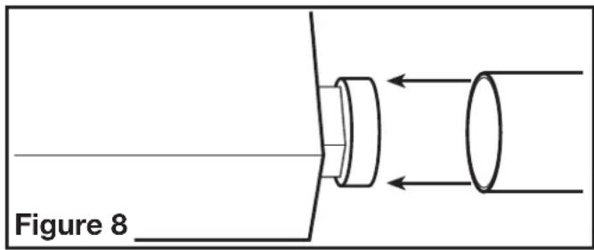
- Remove any tape that might be holding the damper in place. Connect the ducting to the fan's duct collar (Figure 8) and secure in place using tape or screw clamp. Always duct the fan to the outside through a wall or roof cap.
SECTION 5
Wiring
CAUTION: MAKE SURE POWER IS SWITCHED OFF AT SERVICE PANEL BEFORE STARTING INSTALLATION.
WARNING: THIS UNIT MUST BE WIRED ON A SEPARATE 20 AMP CIRCUIT.
WARNING: USE APPROPRIATELY SIZED COPPER CONDUCTORS ONLY RATED FOR AT LEAST 75°C.
CAUTION: ALL ELECTRICAL CONNECTIONS MUST BE MADE IN ACCORDANCE WITH LOCAL CODES, ORDINANCES, OR VICAL CODE. IF YOU ARE UNFAMILIAR WITH METHODS OF INSTALLING BIG, SECURE THE SERVICES OF A QUALIFIED ELECTRICIAN.
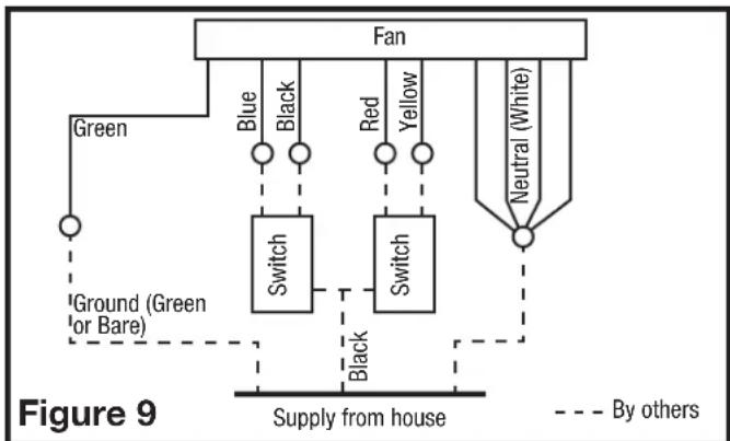
- Using wiring carrying the appropriate rating, run a dedicated line on a 20 amp service from the main service panel to an approved wall junction box (not included). Once inside the junction box, split the hot (black) wire from the home and connect one end to each of the switches into the terminal marked "COMMON TERMINAL". Connect the ground (green or bare copper) wire from the home to the junction box. The neutral (white) wire from the home is not connected to the switch or junction box, but will be run to the unit's wire compartment. Use approved methods for all connections.
- Run wiring from wall switches carrying the appropriate rating. One neutral (white), one ground (green or bare copper), and four hot (black, red, blue, yellow leads connected to the switch, one for each function). Secure the electrical wires to the housing with an approved electrical connector. Make sure you leave enough wiring in the box to make the connection to the fan's receptacles.
- Connect the white wire from the house to the four white wires from the fan. Connect one hot (black) wire from the wall switch to the black wire from the fan (this is the fan control). Connect second hot (red) wire from the wall switch to the red wire from the fan (this is the heat control). Connect the third hot (blue) wire from the wall switch to the blue wire from the fan (this is the main light control). Connect the fourth hot (yellow) wire from the wall switch to the yellow wire from the fan (this is the night light control). Connect the ground wire from the house to the green wire from the fan (Figure 9). Use approved methods for all connections.
flowchart
graph TD
    A["Fan"] --> B["Blue"]
    A --> C["Black"]
    A --> D["Red"]
    A --> E["Yellow"]
    A --> F["Neutral (White)"]
    G["Green"] --> H["Switch"]
    I["Ground (Green or Bare)"] --> H
    J["Supply from house"] --> K["Switch"]
    L["By others"] -.-> M["Switch"]
    N["Source"] -.-> O["Source"]
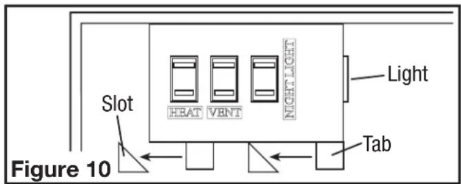
- Reinstall the wire compartment cover by sliding the tabs at the bottom of the cover into the slots in the housing. Make sure all wires are tucked inside of the compartment and are not being pinched or showing through. Reinstall the two screws removed in Step 3 of SECTION 1 Preparing the Unit (Figure 10).
SECTION 6
Completing the Installation
- Insert the plug from the heating unit into the receptacle marked "HEAT", and the plug from the fan into the receptacle marked "VENT" (Figure 11).
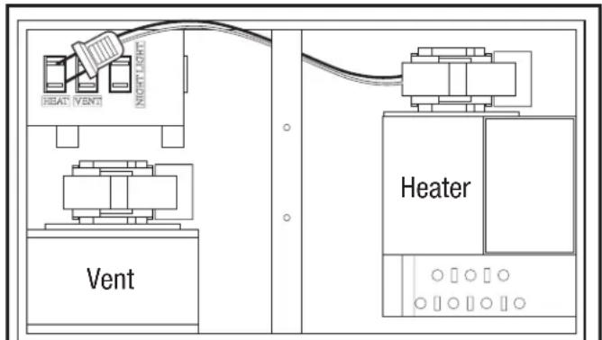
Figure 11
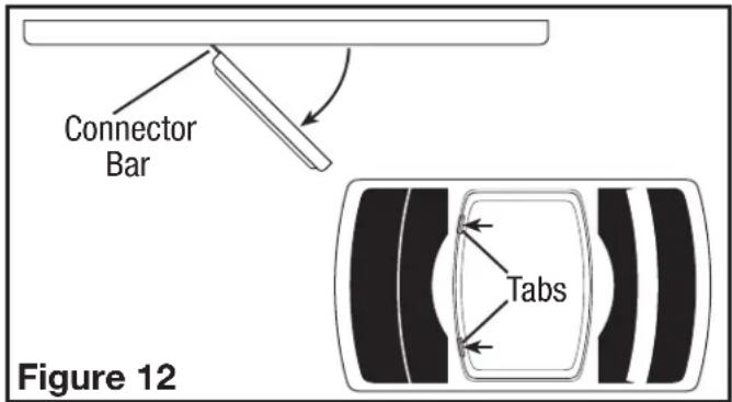
- Remove grill from carton and open light lens area by pushing in on the two tabs of the light lens and pulling outward from lens. The lens will swing open on the connector bars. DO NOT remove the lens from the grill (Figure 12).
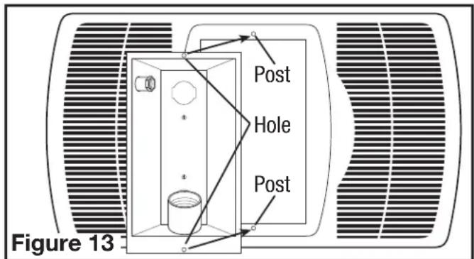
- Install light reflector into grill by lining up the posts on grill with the holes in light reflector (Figure 13). Raise light reflector and grill up to housing and insert plug from light into receptacle marked "LIGHT" (located on the side of the wire compartment) and insert plug from night light into receptacle marked "NIGHT LIGHT"(Figure 11).
- Attach light reflector in place with the two screws removed during Step 2 in SECTION 1 Preparing the Unit so grill fits snuggly against ceiling (Figure 14).
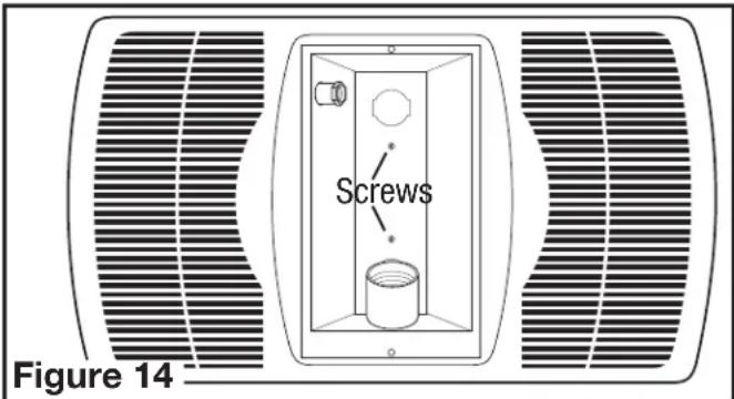

CAUTION: FAILURE TO SECURE THE REFLECTOR SCREWS MAY RESULT IN A RATTLING OR HUMMING NOISE.
- Install the appropriate bulbs (not included) specific to your model:
AK965L: Install a 100 watt maximum, type A19 medium base incandescent bulb (not included) and a 7 watt maximum type C7 (candelabra base) night light (not included).


WARNING: TO REDUCE THE RISK OF FIRE, USE ONLY TYPE GU24 BULB, 26 WATT MAXIMUM.
AKF965: Install an Air King model 26SBL or a compatible GU24 26 watt self ballasted lamp (not included).
- Close the light lens and secure in place by swinging back into position and snapping the tabs in place (Figure 12).
- Restore power and test your installation.
SECTION 7
Operating Instructions


WARNING: HEATER MUST BE PROPERLY INSTALLED BEFORE IT IS USED.
- Each function of the heater is controlled via the wall switches described in SECTION 5 of these instructions.
- This unit utilizes a thermal fuse located in the heater wiring. DO NOT tamper with this device.
- This unit utilizes an automatic resetting limit control located on the heating element housing. DO NOT tamper with this device.
SECTION 8
Maintenance Instructions


CAUTION: MAKE SURE POWER IS SWITCHED OFF AT SERVICE PANEL BEFORE SERVICING THE UNIT.
NOTE: Grill and fan should be cleaned when dust accumulation becomes visible on grill or every 6 months.
- Cleaning the Grill: Reverse the instructions in Section 6 Completing the Installation to remove grill. Use a mild detergent, such as dishwashing liquid, and dry with a soft cloth. NEVER USE ANY ABRASIVE PADS OR SCOURING POWDERS. Completely dry grill before reinstalling. Refer to instructions in Section 6 Completing the Installation, to reinstall grill.
- Cleaning the Fan Assembly: Wipe all parts with a dry cloth or gently vacuum the fan. NEVER IMMERSE ELECTRICAL PARTS IN WATER.
NOTE: Motors in this unit are permanently lubricated. Do not add lubricant.

WARNING: ANY OTHER SERVICING TO THIS UNIT SHOULD BE PERFORMED BY AN AUTHORIZED SERVICE REPRESENTATIVE.

CAUTION: ALLOW BULB TO COOL BEFORE REPLACING.
- Changing the Light Bulb: Disconnect power to the unit. Open light lens by pushing in on the two tabs of light lens and pulling outward from lens. The lens will swing open on the connector bars. DO NOT remove the lens from the grill (Figure 12).
Incandescent Bulb (AK965L): Unscrew bulb from lamp holder and replace with a 100 watt maximum, type A19 medium base incandescent bulb.


WARNING: TO REDUCE THE RISK OF FIRE, USE ONLY TYPE GU24 BULB, 26 WATT MAXIMUM.
Fluorescent Bulb (AKF965): Remove lamp by gently twisting the lamp base counterclockwise while applying outward pressure. Installation is the reverse of removal. Replace with Air King model 26SBL or a compatible GU24 26 watt self ballasted lamp.
Night Light (AK965L, AKF965): Unscrew night light bulb from socket and replace with a 7 watt maximum type C7 (candelabra base) night light bulb.
Troubleshooting Guide
Trouble Probable Cause Suggested Remedy
| 1. Fan does not operate when the switch is on.in housing. Restore power to unit.1d. Motor has stopped operating. 1d. Repace motor. | 1a. A fuse may be blown or a circuit tripped.1b. Connector plug from motor is not plugged in.1c. Wiring is not connected properly.2. Obstruction in the exhaust ducting. | 1a. Replace fuse or reset circuit breaker.1b. Turn off power to unit. Remove Grill and plug motor into receptacle1c. Turn off power to unit. Check that all wires are connected. |
| 2. Fan is operating, but air moves slower than normal. | 2. Check for any obstructions in the ducting. The most common are bird nests in the roof cap or wall cap where the fan exhausts to the outside. | |
| 3. Fan is operating louder than normal.tightened. Restore power to unit.3b. Fan blade is hitting housing of unit. 3b. Callyour dealer for service. | 3a. Motor is loose.3b. Callyour dealer for service. | 3a. Turn off power to unit. Remove grill and check that all screws are fully |
LIMITED WARRANTY
WHAT THIS WARRANTY COVERS: This product is warranted against defects in workmanship and/or materials.
HOW LONG THIS WARRANTY LASTS: This warranty extends only to the original purchaser of the product and lasts for one (1) year from the date of original purchase or until the original purchaser of the product sells or transfers the product, whichever first occurs.
WHAT AIR KING WILL DO: During the warranty period, Air King will, at its sole option, repair or replace any part or parts that prove to be defective or replace the whole product with the same or comparable model.
WHAT THIS WARRANTY DOES NOT COVER: This warranty does not apply if the product was damaged or failed because of accident, improper handling or operation, shipping damage, abuse, misuse, unauthorized repairs made or attempted. This warranty does not cover shipping costs for the return of products to Air King for repair or replacement. Air King will pay return shipping charges from Air King following warranty repairs or replacement
ANY AND ALL WARRANTIES, EXPRESSED OR IMPLIED (INCLUDING, WITHOUT LIMITATION, ANY IMPLIED WARRANTY OF MERCHANTABILITY), LAST ONE YEAR FROM THE DATE OF ORIGINAL PURCHASE OR UNTIL THE ORIGINAL PURCHASER OF THE PRODUCT SELLS OR TRANSFERS THE PRODUCT, WHICHEVER FIRST OCCURS AND IN NO EVENT SHALL AIR KING'S LIABILITY UNDER ANY EXPRESS OR IMPLIED WARRANTY INCLUDE (I) INCIDENTAL OR CONSEQUENTIAL DAMAGES FROM ANY CAUSE WHATSOEVER, OR (II) REPLACEMENT OR REPAIR OF ANY HOUSE FUSES, CIRCUIT BREAKERS OR RECEPTACLES. NOTWITHSTANDING ANYTHING TO THE CONTRARY, IN NO EVENT SHALL AIR KING'S LIABILITY UNDER ANY EXPRESS OR IMPLIED WARRANTY EXCEED THE PURCHASE PRICE OF THE PRODUCT AND ANY SUCH LIABILITY SHALL TERMINATE UPON THE EXPIRATION OF THE WARRANTY PERIOD.
Some states and provinces do not allow limitations on how long an implied warranty lasts, or the exclusion or limitation of incidental or consequential damages, so these exclusions or limitations may not apply to you. This warranty gives you specific legal rights. You may also have other rights which vary from state to state and province to province. Proof of purchase is required before a warranty claim will be accepted.
CUSTOMER SERVICE:
Toll-Free (800) 465-7300
Our Customer Service team is available to assist you with product questions, service center locations, and replacement parts. They can be reached Monday through Friday, 8am-4pm Eastern.
Please have your model number available, as well as the type and style (located on the label inside of your product).
Please do not return product to place of purchase.
www.airkinglimited.com
PARTS FOR DISCONTINUED, OBSOLETE AND CERTAIN OTHER PRODUCTS MAY NOT BE AVAILABLE. DUE TO SAFETY REASONS, MANY ELECTRONIC COMPONENTS AND MOST HEATER COMPONENTS ARE NOT AVAILABLE TO CONSUMERS FOR INSTALLATION OR REPLACEMENT.
Installer:
Place of Purchase:
Installation Date:
Model Number:
NOTES
INSTRUCTIONS IMPORTANTES - MANUEL D'OPÉRATION
Modèles: AK-965L

natural_image
Technical line drawing of a mechanical component with mounting holes and a central shaft (no text or symbols)SECTION 3
Construction Existante
natural_image
Technical line drawing of a mechanical assembly with a tool and bracket (no text or symbols)natural_image
Technical line drawing of a mechanical assembly with a tool and bracket (no text or symbols)SECTION 4
Conduits

ATTENTION : TOUS LES CONDUITS DOIVENT ÊTRE CONFORMES AUX CODES DU BÂTIMENT LOCAUX ET NATIONAUX.

ATTENTION : UN MANQUEMENT À BIEN SERRER LES VIS DU RÉFLECTEUR PEUT RÉSULTER EN UN BRUIT DE CRÉCELLEMENT OU DE GRONDEMENT.
- IMPORTANT INSTRUCTIONS - OPERATING MANUAL
- READ AND SAVE THESE INSTRUCTIONS
- RETAIN INSTRUCTIONS FOR FUTURE REFERENCE.
- GENERAL SAFETY INFORMATION
- INSTALLATION INSTRUCTIONS
- SECTION 1
- Preparing the Exhaust Fan
- SECTION 2
- New Construction
- SECTION 3
- Existing Construction
- SECTION 4
- Ducting
- CAUTION: ALL DUCTING MUST COMPLY WITH LOCAL AND NATIONAL BUILDING CODES.
- SECTION 5
- Wiring
- SECTION 6
- Completing the Installation
- CAUTION: FAILURE TO SECURE THE REFLECTOR SCREWS MAY RESULT IN A RATTLING OR HUMMING NOISE.
- WARNING: TO REDUCE THE RISK OF FIRE, USE ONLY TYPE GU24 BULB, 26 WATT MAXIMUM.
- SECTION 7
- Operating Instructions
- WARNING: HEATER MUST BE PROPERLY INSTALLED BEFORE IT IS USED.
- SECTION 8
- Maintenance Instructions
- CAUTION: MAKE SURE POWER IS SWITCHED OFF AT SERVICE PANEL BEFORE SERVICING THE UNIT.
- WARNING: ANY OTHER SERVICING TO THIS UNIT SHOULD BE PERFORMED BY AN AUTHORIZED SERVICE REPRESENTATIVE.
- CAUTION: ALLOW BULB TO COOL BEFORE REPLACING.
- Troubleshooting Guide
- LIMITED WARRANTY
- CUSTOMER SERVICE:
- NOTES
- INSTRUCTIONS IMPORTANTES - MANUEL D'OPÉRATION
- Construction Existante
- ATTENTION : TOUS LES CONDUITS DOIVENT ÊTRE CONFORMES AUX CODES DU BÂTIMENT LOCAUX ET NATIONAUX.
Brand : Air King
Model : AK965L
Category : Heating