talento smart LAN - Switch Grässlin - Free user manual and instructions
Find the device manual for free talento smart LAN Grässlin in PDF.

User questions about talento smart LAN Grässlin
0 question about this device. Answer the ones you know or ask your own.
Ask a new question about this device
Download the instructions for your Switch in PDF format for free! Find your manual talento smart LAN - Grässlin and take your electronic device back in hand. On this page are published all the documents necessary for the use of your device. talento smart LAN by Grässlin.
USER MANUAL talento smart LAN Grässlin
IoT (Internet of things)....21
PIN festlegen....22
PIN löschen....23
Bluetooth-Einstellungen ablesen 24
Registration numbers ....30
Übersicht
Aufbau und Funktion

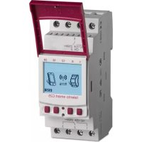
text_image
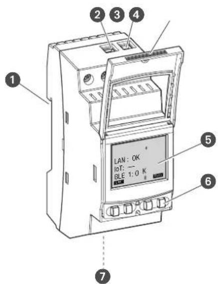
1 2 3 4 5 LAN: OK IOT: — BLE 1:0 K 6 7Abb. 1: LAN-Modul
natural_image
Pure diagram of a mechanical or architectural component with an arrow indicating direction (no text or symbols)- AM = Vormittag
- PM = Nachmittag
IoT (Internet of things)
text_image
Diagram showing wireless signal transmission between a device and a mobile phone, with a Bluetooth symbol above the device.This manual ensures safe and efficient use of the LAN module (referred to as “device” in the following). This manual is a component of the device and must remain accessible at all times for everyone who uses the device.
Everyone who uses the device must have read and understood this manual before commencing any work. The basic prerequisite for working safely is compliance with all safety instructions and usage instructions specified in this manual. Furthermore, the local accident prevention regulations and the general safety regulations in the area in which the device is operated apply.
Copyright
This manual is copyright protected.
Handover of this manual to third parties, reproductions of any type and form – including excerpts – and use and/or disclosure of the content without the written permission of the manufacturer, except for internal purposes, is not permitted. Violations will result in liability for compensation. The manufacturer reserves the right to assert additional claims.
The copyright is held by the manufacturer.
Download
You can find the following information at www.graesslin.de:
- Download instructions
- Technical data
Declaration of conformity
Grässlin GmbH hereby declares that the radio system type “talento smart LAN” conforms to Directive 2014/53/EU. The complete text of the EU declaration of conformity is available from the following Internet address: https://gr.greesslie.de/talento-snfart-conformity.

Overview....32
Design and function....32

Safety....36

Installation....39

Configuration....41
Initial commissioning....41
Setting the language 41
Setting the date and time 42
Network settings....44
DHCP/SLAAC 44
Device IP 45
NETMASK 46
GATEWAY 47
DNS server....48
IoT (Internet of things)....49
Specifying the PIN 50
Deleting the PIN 51
Reading the Bluetooth settings 52
Connecting the LAN module to the DIN-rail timer....53
Disconnecting the DIN-rail timer from the LAN module ....55
Configuring the LAN module via mobile devices....56

Disposal 57
Overview
Design and function
text_image
1 2 3 4 5 LAN : OK IOT : — BLE 1:0 K 6 7Fig. 1: LAN module
1 Click system for installation on a DIN rail
2 Terminal for phase
3 Terminal for neutral conductor
4 Sealable housing
5 Display
6 Control buttons
7 Network connection (Ethernet) RJ45
Description of function
The LAN module is installed on a DIN rail (Fig. 1/1) by means of a click system and is connected to the LAN via the Ethernet interface. It enables convenient management of up to five talento smart S25 DIN-rail timers. Programming can be easily exported and transferred via a PC in the LAN or a mobile device via WLAN. The DIN-rail timers are connected to the LAN module via Bluetooth. The radio signal frequency is 2.4 GHz and the maximum transmission power is 1.8 mW.
Technical data (DIN EN 60730-1)
Mode of operation 1.B
Pollution degree 2
Rated impulse voltage 4000 V
The technical data for the devices described in this manual can be found at: http://qrc.graesslin.de/talento-smart-specs.
Display and control elements
text_image
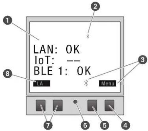
LAN: OK IoT: -- BLE 1: OK LA MenuFig. 2: Display layout
1 Connection type
2 Bluetooth
3 Function displays of the buttons on the right
4 Menu button
5 Bluetooth button
6 Reset button
7 Buttons on the left
8 Function displays of the buttons on the left
Function displays of the two buttons on the right (Fig. 2/4 + 5)
DisplayFunction
Menu Enter programming mode.
Bluetooth Pressing this button activates the Bluetooth function and enables a connection to be established.
ESC Press briefly = goes back one step.
Press and hold (2 seconds) = back to automatic mode.
OK Make the selection and apply it.
< Undo the last input, e.g. when entering the time.
Function of the two buttons on the left (Fig. 2/7)
DisplayFunction
LAN
The IP address of the device is displayed.
K
Page up in the menu
K
Page down in the menu.
- Press briefly = reduce the displayed value (hour, minute, second) by 1.
Press and hold (2 seconds) = fast cycling.
+ Press briefly = increase the displayed value (hour, minute, second) by 1.
Press and hold (2 seconds) = fast cycling.
Menu structure
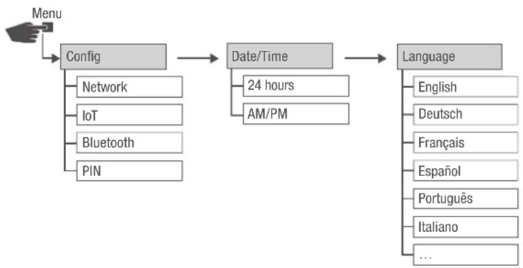
flowchart
graph TD
    A["Menu"] --> B["Config"]
    B --> C["Date/Time"]
    C --> D["Language"]
    B --> E["Network"]
    B --> F["IoT"]
    B --> G["Bluetooth"]
    B --> H["PIN"]
    C --> I["24 hours"]
    C --> J["AM/PM"]
    D --> K["English"]
    D --> L["Deutsch"]
    D --> M["Français"]
    D --> N["Espanol"]
    D --> O["Português"]
    D --> P["Italiano"]
    D --> Q["..."]
Fig. 3: Menu structure
The menu structure appears on the display when you press the menu button (Fig. 2/4).
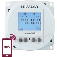
Downloading the app

Fig. 4: Mobile app
The LAN module can be programmed using a mobile device.
The mobile app is available for Android or for iOS devices; alternatively, scan the QR code shown here and install the app.
Downloading the PC software
Using the PC software, you can program the talento smart S25 DIN-rail timers via the LAN module.
The PC software is available for download at:
http://www.graesslin.de
Safety
Safety instructions
Safety instructions are indicated in this manual by symbols. The safety instructions are introduced by signal words that express the extent of the danger.

WARNING!
This combination of symbol and signal word indicates a potentially dangerous situation that may result in death or severe injuries if the situation is not avoided.

CAUTION!
This combination of symbol and signal word indicates a potentially dangerous situation that may result in minor or slight injuries if the situation is not avoided.

NOTE!
This combination of symbol and signal word indicates a potentially dangerous situation that may result in material damage if the situation is not avoided.

ENVIRON- MENTAL PROTECTION!
This combination of symbol and signal word indicates potential dangers for the environment.
Tips and recommendations

This symbol highlights useful tips and recommendations, as well as information for efficient and fault-free operation.
Intended use
- The LAN module is intended solely for programming talento smart S25 DIN-rail timers in private and commercial areas.
- The LAN module may only be installed on DIN rails.
- Only use the LAN module in dry rooms and do not install close to devices with inductive discharge (motors, transformers, etc.).
The intended use also includes compliance with all information specified in this manual.
Any use other than the intended use is considered incorrect use. The legal warranty is voided by any interference with, or modifications to, the device.

WARNING!
Danger due to insufficient wire cross-section!
If wires with an insufficiently large cross-section are used, short circuits or fires may occur.
- Only use terminals with a cross-section between 1mm^2 and 2.5mm^2 for flexible wires.

NOTE!
Damage to the DIN-rail timer due to incorrect installation location!
If installed in an unsuitable location, the DIN-rail timer may be damaged.
- Only use the DIN-rail timer in dry rooms and do not install close to devices with inductive discharge (motors, transformers, etc.).
- Only install the DIN-rail timer on DIN rails.
Residual risks
The device is state-of-the-art and designed in accordance with current safety requirements.
However, residual risks remain that require caution when using the device. The residual risks, and the conduct and measures they require, are listed in the following.
Electric current

WARNING!
Risk of fatal electric shock!
Improper assembly and installation of the device can lead to life-threatening electrical voltages.
- Only allow a qualified electrician to install and connect the device.
Personnel requirements

Qualified electrician
Professional training, knowledge and experience, and knowledge of the relevant standards and regulations allows the qualified electrician to perform work on electrical systems and to identify, and avoid, potential dangers of their own accord.
A qualified electrician is specifically trained for the work environment in which they work, and are familiar with the relevant standards and regulations.
Installation
Connecting the electricity

WARNING!
Risk of fatal electric shock!
Improper assembly and installation of the device can lead to life-threatening electrical voltages.
- Only allow a qualified electrician to install and connect the device.
Personnel:
• Qualified electrician
Material:
• DIN rail (15 mm x 7.5 mm)
• DIN rail (15 mm x 12.5 mm)
Prerequisite:
• The terminals for the flexible wires must have a cross-section between 1 mm ^2 and 2.5 mm ^2 .

natural_image
Abstract geometric shape with a curved arrow indicating rotation or movement (no text or symbols)Fig. 5: Installation on a DIN rail
- Place the LAN module on the DIN rail (Fig. 5) from above and press it back until it locks into place.
Connecting the electricity
- Strip the insulation from the wires.
- Stripping length: 8 mm

NOTE!
Tightening torques
To avoid damage and faulty contacts, tighten the terminals using a torque of 1.2 – 1.4 Nm.
RJ45

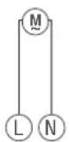
Fig. 6: Circuit diagram
- Connect the LAN module as per the circuit diagram (Fig. 6).
- Connect the LAN module to the network via the RJ45 interface.
Configuration
Initial commissioning
Condition on delivery
When delivered, the device is in the language (English).
Language, date and time, PIN, Bluetooth connection and integration in the LAN network are to be programmed subsequently.
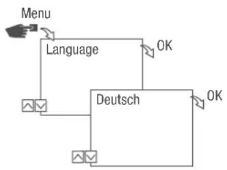
Setting the language
flowchart
graph TD
    A["Menu"] --> B["Language"]
    B --> C["Deutsch"]
    C --> D["OK"]
    D --> E["OK"]
Fig. 7: Setting the language
- Press the Menu button.
- Select Language and confirm with OK.

During initial commissioning, this will always read Language (in English).
- Select the language and confirm with OK.
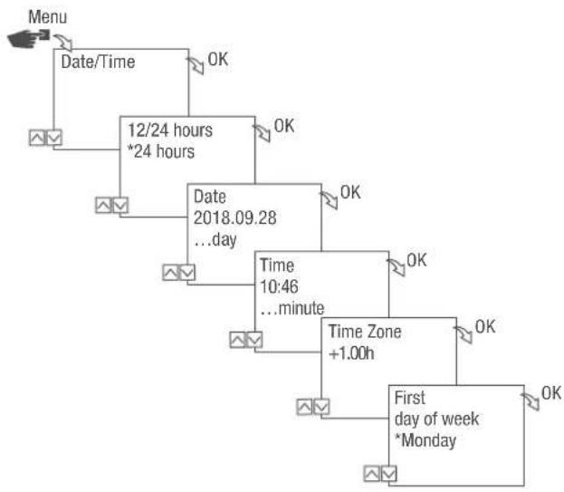
Setting the date and time
flowchart
graph TD
    A["Menu"] --> B["Date/Time"]
    B --> C["12/24 hours *24 hours"]
    C --> D["Date 2018.09.28 ...day"]
    D --> E["Time 10:46 ...minute"]
    E --> F["Time Zone +1.00h"]
    F --> G["First day of week *Monday"]
    G --> H["OK"]
    C --> I["OK"]
    D --> J["OK"]
    E --> K["OK"]
    F --> L["OK"]
    G --> M["OK"]
Fig. 8: Setting the date and time
- Press the Menu button.
- Select Date/Time and confirm with OK.
- Select the desired time display (→ "Possible time displays" on page 43) and confirm with OK.
- Enter the date and confirm with OK.
- Enter the time and confirm with OK.
- Enter the time zone and confirm with OK.
- Enter the first day of the week and confirm with OK.

Selecting the day of the week
Example:
- 1st day = Sunday... 1 - 5 = Sun - Thu
- 1st day = Monday... 1 - 5 = Mon - Fri
Possible time displays
SettingEffect
24 hours The time is displayed in 24 hour format.
AM/PM The time is displayed in 12 hour format.
- AM = morning
- PM = afternoon
Network settings
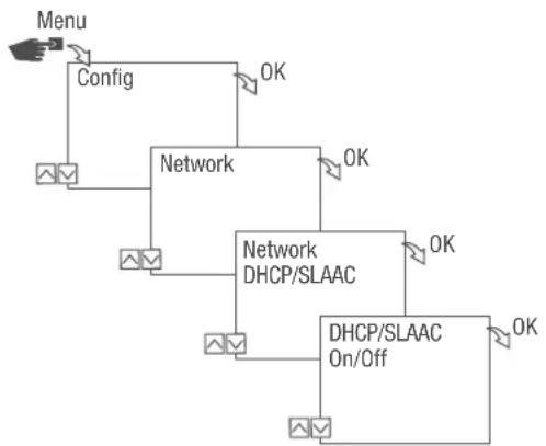
DHCP/SLAAC
The Dynamic Host Configuration Protocol (DHCP) makes it possible for your LAN module to be automatically assigned an individual network address and integrated into your network.
Stateless Address Autoconfiguration (SLAAC) is a procedure for stateless and automatic configuration of IPv6 addresses on a network interface. In this regard, the respective IPv6 address is not assigned and stored centrally. The host generates its own IPv6 address using additional information. SLAAC is the further development of methods for classic IP auto-configuration under IP4. In contrast to IPv4, IPv6 routers play an active role in this context.
flowchart
graph TD
    A["Menu"] --> B["Config"]
    B --> C["Network"]
    C --> D["Network DHCP/SLAAC"]
    D --> E["DHCP/SLAAC On/Off"]
    E --> F["OK"]
    C --> G["OK"]
    D --> H["OK"]
Fig. 9: Switching DHCP/SLAAC on and off
- Press the Menu button.
- Select Config and confirm with OK.
- Select Network and confirm with OK.
- Select DHCP/SLAAC and confirm with OK.
- Select ON or OFF and confirm with OK.
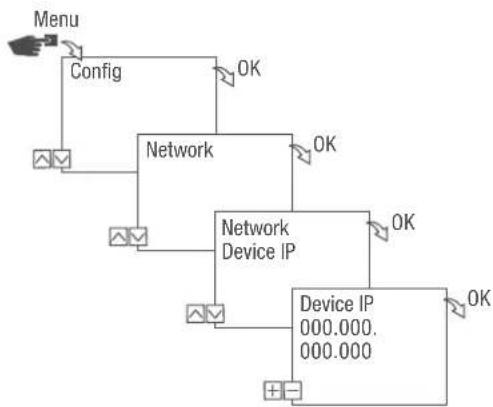
DEVICE IP
If DHCP/SLAAC is switched off, you can enter the IP address of your device manually.
flowchart
graph TD
    A["Menu"] --> B["Config"]
    B --> C["Network"]
    C --> D["Network Device IP"]
    D --> E["Device IP 000.000.000.000"]
    C --> F["OK"]
    D --> G["OK"]
    E --> H["OK"]
Fig. 10: Specifying the device IP
- Press the Menu button.
- Select Config and confirm with OK.
- Select Network and confirm with OK.
- Select Device IP and confirm with OK.
- Enter the IP address and confirm with OK.
NETMASK
If DHCP/SLAAC is switched off, you can enter the netmask manually.

flowchart
graph TD
    A["Menu"] --> B["Config"]
    B --> C["Network"]
    C --> D["Network Netmask"]
    D --> E["Netmask 000.000.000.000"]
    C --> F["OK"]
    D --> G["OK"]
    E --> H["OK"]
Fig. 11: Specifying the netmask
- Press the Menu button.
- Select Config and confirm with OK.
- Select Network and confirm with OK.
- Select Netmask and confirm with OK.
- Enter the netmask and confirm with OK.
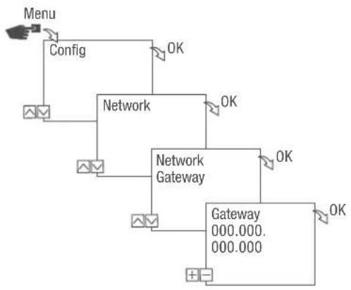
GATEWAY
If DHCP/SLAAC is switched off, you can enter the gateway manually.
flowchart
graph TD
    A["Menu"] --> B["Config"]
    B --> C["Network"]
    C --> D["Network Gateway"]
    D --> E["Gateway 000.000.000.000"]
    C --> F["OK"]
    D --> G["OK"]
    E --> H["OK"]
Fig. 12: Specifying the gateway
- Press the Menu button.
- Select Config and confirm with OK.
- Select Network and confirm with OK.
- Select Gateway and confirm with OK.
- Enter the IP address and confirm with OK.
DNS SERVER
If DHCP/SLAAC is switched off, you can enter the DNS server manually.

flowchart
graph TD
    A["Menu"] --> B["Config"]
    B --> C["Network"]
    C --> D["Network DNS server"]
    D --> E["DNS server 000.000.000.000"]
    C --> F["OK"]
    D --> G["OK"]
    E --> H["OK"]
Fig. 13: Specifying the DNS server
- Press the Menu button.
- Select Config and confirm with OK.
- Select Network and confirm with OK.
- Select DNS server and confirm with OK.
- Enter the IP address and confirm with OK.
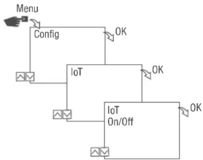
IoT (Internet of things)
You need registered access to our cloud in order to use IoT. You can create such access using our PC software or our app.
flowchart
graph TD
    A["Menu"] --> B["Config"]
    B --> C["IoT"]
    C --> D["On/Off"]
    D --> E["OK"]
    C --> F["OK"]
    style A fill:#f9f,stroke:#333
    style B fill:#ccf,stroke:#333
    style C fill:#cfc,stroke:#333
    style D fill:#fcc,stroke:#333
    style E fill:#ffc,stroke:#333
Fig. 14: Switching IoT on and off
- Press the Menu button.
- Select Config and confirm with OK.
- Select IoT and confirm with OK.
- Select ON or OFF and confirm with OK.
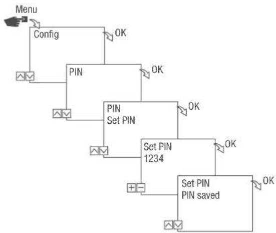
Specifying the PIN
flowchart
graph TD
    A["Menu"] --> B["Config"]
    B --> C["PIN"]
    C --> D["SET PIN"]
    D --> E["Set PIN 1234"]
    E --> F["Set PIN PIN saved"]
    C --> G["OK"]
    D --> H["OK"]
    E --> I["OK"]
    F --> J["OK"]
Fig. 15: Specifying the PIN
- Press the Menu button.
- Select Config and confirm with OK.
- Select PIN and confirm with OK.
- Select Enter PIN and confirm with OK.
- Enter the PIN using the left-hand buttons ( / ) and confirm with OK.
All configurations and manual operations are protected by PIN and cannot be changed without entering the PIN.
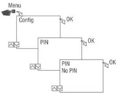
Deleting the PIN
flowchart
graph TD
    A["Menu"] --> B["Config"]
    B --> C["PIN"]
    C --> D["No PIN"]
    D --> E["PIN"]
    E --> F["OK"]
    style A fill:#f9f,stroke:#333
    style B fill:#ccf,stroke:#333
    style C fill:#cfc,stroke:#333
    style D fill:#fcc,stroke:#333
    style E fill:#cff,stroke:#333
Fig. 16: Deleting the PIN
- Press the Menu button.
- Select Config and confirm with OK.
- Select PIN and confirm with OK.
- Select No PIN and confirm with OK.
Reading the Bluetooth settings
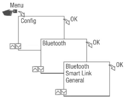
flowchart
graph TD
    A["Menu"] --> B["Config"]
    B --> C["Bluetooth"]
    C --> D["Bluetooth Smart Link General"]
    D --> E["OK"]
    C --> F["OK"]
Fig. 17: Bluetooth settings
- Press the Menu button.
- Select Config and confirm with OK.
- Select Bluetooth and confirm with OK.
- Select Smart Link or General and confirm with OK.
→ You can read the settings (⇨ "Bluetooth settings" on page 52).

You can change the device name via mobile devices.
Bluetooth settings
MenuSettings
Smart Link MAC address
Device names
General Version number of software
Serial number of device
Connecting the LAN module to the DIN-rail timer
Preparing for the connection
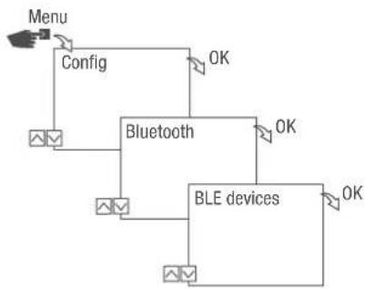
flowchart
graph TD
    A["Menu"] --> B["Config"]
    B --> C["Bluetooth"]
    C --> D["BLE devices"]
    D --> E["OK"]
    C --> F["OK"]
    C --> G["OK"]
Fig. 18: Establishing a Bluetooth connection to the LAN module
- Press the Menu button on the LAN module.
- Select Config and confirm with OK.
- Select Bluetooth and confirm with OK.
- Select BLE devices and confirm with OK.
text_image
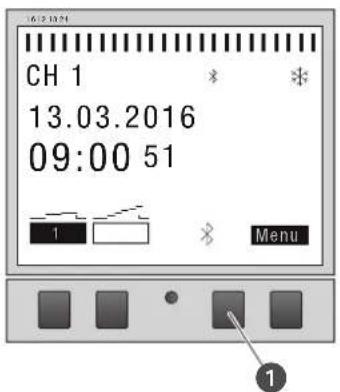
CH 1 13.03.2016 09:00 51 1 MenuFig. 19: Establishing a Bluetooth connection to the DIN-rail timer
- Press the Bluetooth button (Fig. 15/①) on the DIN-rail timer.
The Bluetooth symbol flashes. A list of all available devices in the vicinity is shown on the LAN module display.
Establishing the connection
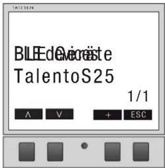
text_image
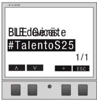
BLEEdVicriste TalentoS25 1/1 A V + ESCFig. 20: Selecting the DIN-rail timer
- On the LAN module, select the DIN-rail timer to be connected from the list using the buttons on the left ( / ) and confirm with +.

The DIN-rail timer that is connected is marked with # and with a black background.
- Select a further DIN-rail timer with the buttons on the left (A/V) and confirm with +.
Disconnecting the DIN-rail timer from the LAN module
text_image
BILEdeOvereste #TalentoS25 1/1 A V + ESCFig. 21: Selecting the DIN-rail timer
- On the LAN module, select the DIN-rail timer to be disconnected from the list using the buttons on the left ( / ) and confirm with +.

The DIN-rail timers that are connected are marked with # and with a black background.
- Select a further DIN-rail timer with the buttons on the left ( / ) and confirm with -.
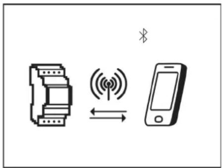
Configuring the LAN module via mobile devices
Connection to mobile devices
The LAN module can be configured directly via a LAN connection using a mobile device. To this end, the mobile device or PC needs to have access to the network (same network, VPN, cloud, ...).
text_image
Diagram showing wireless signal transmission between a device and a mobile phone, with Chinese character 'X' above the device.Fig. 22: Display during data transmission

To configure the LAN module using a mobile device, you require the corresponding mobile app. The mobile app is available for Android or for iOS devices; alternatively, scan the QR code shown here and install the app.

Using the PC software, you can program the talento smart S25 DIN-rail timers via the LAN module.
The PC software is available for download at:
http://www.graesslin.de
Disposal
Improper disposal

ENVIRON- MENTAL PROTECTION!
Incorrect disposal presents an environmental danger.
Incorrect disposal could result in environmental dangers.
- Electric scrap and electronic components must be disposed of correctly, i.e. the parts for disposal must be sorted into material groups.
- Disposal must be environmentally responsible and must employ state-of-the-art environmental protection, recycling and disposal technology.
Recycling
If no agreement has been made covering return or disposal, ensure that the dismantled components are recycled:
- Scrap metals.
- Ensure plastic elements are recycled.
- Dispose of other components after sorting them according to material properties.

natural_image
Pure diagram of a mechanical or architectural component with an arrow indicating direction (no text or symbols)text_image
Diagram showing wireless signal transmission between a device and a mobile phone, with Chinese character 'X' above the device.natural_image
Pure diagram of a mechanical component with an arrow indicating direction (no text or symbols)- Día 1 = lunes... 1–5 = Lun–Vie
text_image
Diagram showing wireless signal transmission between a device and a mobile phone, with Chinese character 'X' above the device.Registration numbers
Canada / USA
FCC-Zertifizierung
FCC ID: 2AHH7-DG
This device complies with Section 15 of the FCC Regulations. Operation is only permitted under the following conditions: (1) This device must not cause any disruptive interferences and (2) the device must be able to receive interferences, also such interferences which could result in undesired operations.