ATM350UL - Microphone AUDIO TECHNICA - Free user manual and instructions
Find the device manual for free ATM350UL AUDIO TECHNICA in PDF.
| Product Type | Cardioid condenser instrument microphone |
| Model | ATM350UL (kit with AT8490L, AT8491U, AT8543, AT8468, rigid case) |
| Polar Pattern | Cardioid |
| Frequency Response | 40 – 20,000 Hz |
| Low-Cut Filter | 80 Hz, 12 dB/octave (on AT8543 module) |
| Sensitivity | -49 dB (3.5 mV) at 1 kHz, 1 V/Pa |
| Impedance | 200 ohms |
| Maximum SPL | 159 dB SPL (1 kHz, 1% THD) |
| Dynamic Range | 130 dB (1 kHz at max SPL) |
| Signal-to-Noise Ratio | 65 dB (1 kHz, 1 Pa, A-weighted) |
| Phantom Power | 11 – 52 V DC, 3.5 mA |
| Dimensions (Microphone) | Length 37.8 mm, diameter 12.2 mm |
| Dimensions (AT8543 module) | Length 92 mm, diameter 18.9 mm |
| Weight (Microphone) | 14.5 g |
| Weight (AT8543 module) | 90 g |
| Output Connector | XLRM 3-pin integrated on module |
| Cable | 4 m, diameter 3.2 mm, shielded, HIROSE HR10 connector |
| Interchangeable Capsules (optional) | UE-O omnidirectional, UE-H hypercardioid |
| Included Accessories | AT8543 module, AT8491U mount, AT8490L gooseneck, AT8468 violin mount, rigid case |
| Maintenance and Cleaning | Avoid prolonged exposure to sunlight, temperatures >43°C, high humidity. Clean with a soft dry cloth. |
| Safety | Do not subject to violent shocks. Do not disassemble, modify or repair. Do not handle with wet hands. Store away from heat, humidity and dust. |
| Repairability and Spare Parts | Interchangeable capsules available as option. No user-serviceable parts listed. Contact authorized service center for repair. |
Frequently Asked Questions - ATM350UL AUDIO TECHNICA
User questions about ATM350UL AUDIO TECHNICA
0 question about this device. Answer the ones you know or ask your own.
Ask a new question about this device
Download the instructions for your Microphone in PDF format for free! Find your manual ATM350UL - AUDIO TECHNICA and take your electronic device back in hand. On this page are published all the documents necessary for the use of your device. ATM350UL by AUDIO TECHNICA.
USER MANUAL ATM350UL AUDIO TECHNICA
Cardioid Condenser Instrument Microphone
text_image
Diagram showing four steps of a cable installation with labeled components and directional arrows indicating sequence.マウントにグースネックを固定する

text_image
Diagram showing a mechanical assembly with labeled parts and directional arrows indicating motion or movement.text_image
Diagram illustrating a medical procedure involving a surgical instrument and a device, labeled with numbered steps.natural_image
Line drawing of a grand piano with an inset showing a mechanical device connected to a floor (no text or symbols present)natural_image
Mechanical assembly diagram showing a linkage mechanism with no visible text or symbols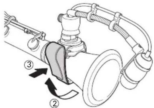
text_image
Technical diagram of a mechanical device with labeled parts and directional arrows indicating motion or assembly.
natural_image
Technical diagram of a mechanical assembly with hoses and rotating components (no text or symbols)text_image
Diagram illustrating foot massage technique with labeled parts and directional arrows indicating movement2.

natural_image
Technical line drawing of a mechanical clamp or bracket assembly (no text or symbols)text_image
Technical diagram of a mechanical assembly with labeled parts ① and ②, showing directional arrows and components.AT8491G
ギターマウント
1.

text_image
Diagram illustrating guitar mode and playback mechanism with labeled parts ①, ②, and directional arrows indicating movement.2.
text_image
Diagram illustrating guitar chord joint movement with numbered instructions and directional arrowstext_image
Technical diagram showing mechanical assembly with numbered components and directional arrows indicating motion or flow2.
natural_image
Mechanical assembly diagram showing a linkage mechanism with no visible text or symbolstext_image
Technical diagram showing mechanical assembly with labeled components 1, 2, and 3radar
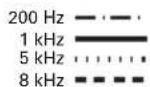
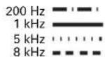
| Angle | Value | |-------|-------| | 0° | High | | 30° | Medium| | 60° | Low | | 90° | Medium| | 120° | Low | | 150° | Medium| | 180° | Low | | 210° | Medium| | 240° | Low | | 270° | Medium| | 300° | Low | | 330° | High |凡例
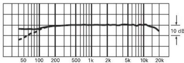
音圧スケールは 1 目盛 5dB
周波数特性
40–20,000 Hz
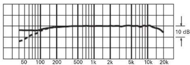
line
| x | y | | ---- | ----- | | 50 | 0.5 | | 100 | 0.8 | | 200 | 0.9 | | 500 | 0.95 | | 1k | 0.98 | | 2k | 0.97 | | 5k | 0.96 | | 10k | 0.94 | | 20k | 0.85 |レスポンス (dB)
凡例
| 0°, 50 cm | |
| ローカット |
Thank you for purchasing this product. Before using the product, read through the user manual to ensure that you will use the product correctly. Please keep this manual for future reference.
Features
- Crisp, clear, well-balanced response, even at high SPLs
- Attaches to brass, reeds, piano, snare, toms violin, guitar and accordion
• Dedicated mounting systems permit accurate positioning, provide shock resistance and element protection - AT8543 power module is equipped with switchable 80-Hz low frequency sounds
- Interchangeable elements available for hyper cardioid and omnidirectional polar patterns
- Also available in a wireless model, ATM350acW and ATM350acH
Caution
- Do not subject the product to strong impact to avoid malfunction.
- Do not disassemble, modify or attempt to repair the product.
- Do not handle the product with wet hands to avoid electric shock or injury.
- Do not store the product under direct sunlight, near heating devices or in a hot, humid or dusty place.
ATM350a Description
The ATM350a is a fixed-charge condenser microphone with a cardioid polar pattern. It is designed for use in professional live-sound and studio applications.
When used with the available mounts and mounting systems, it provides accurate, consistent pickup of brass, woodwind, piano, drums and many other musical instruments.
The flexible gooseneck allows for precise microphone positioning even under demanding performances.
The cardioid polar pattern of the microphone is more sensitive to sound originating directly in front of the element, making it useful for controlling feedback and reducing pickup of unwanted sounds.
The microphone includes a 4 m (13.1') permanently attached miniature cable. Its free end connects to the provided AT8543 power module via a locking 4-pin connector. The output of the power module is a 3-pin XLRM-type connector.
A switch in the power module permits choice of flat response or low-frequency roll-off (via integral 80 Hz high-pass filter) to help control undesired ambient noise.
The microphone is enclosed in a rugged housing with a low-reflectance black finish.
ATM350acW Description
The microphone is also available as the ATM350acW wireless model. The ATM350acW features a 1.4 m (55") miniature cable terminated with a locking 4-pin connector for use with Audio-Technica body-pack transmitters.
The ATM350acW specifications are identical to those of the ATM350a (when using an AT8543 power module). However, no power module is included with the ATM350acW, so there is no low-cut function.
ATM350acH Description
The microphone is also available as the ATM350acH wireless model. The ATM350acH features a 1.4 m (55") miniature cable terminated with a screw-down 4-pin connector for use with Audio-Technica cH-style body-pack transmitters. No power module is included (or required) with the ATM350acH. The ATM350acH specifications are identical to those of the ATM350a.
AT8490/AT8490L Description
The AT8490/AT8490L flexible gooseneck permits aiming the microphone in any direction, while a cable strain relief reduces cable-transmitted noise and cable damage. The integral windscreen entirely surrounds the microphone with foam to isolate the microphone from noise transmitted from the instrument and shield the element against accidental damage.
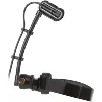
AT8491U Description
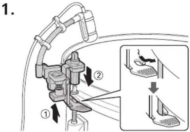
Universal clip-on mount features rugged metal construction to withstand the rigor of stage use. The mount is lined with rubber to provide secure mounting, shock resistance and instrument protection. Specially designed mount minimizes contact with instrument. A locking screw holds the mount securely in place.
AT8491P Description
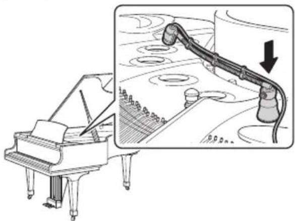
Piano mount features a strong rare-earth magnet which permits secure mounting inside a piano or on any metal surface. The mounting base is lined with soft and protective material to avoid damaging the instrument.
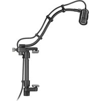
AT8491W Description
The woodwind mount features an adjustable hook and loop fastener strap with rubber pad to firmly secure the mount to the instrument. Specially designed mount minimizes contact with instrument to reduce damping. Rotating gooseneck mount allows easy positioning of the microphone.
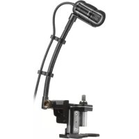
AT8491D Description
The drum mount features a patented design which uses the drum lug to securely mount the microphone while still allowing the drum to be tuned. The gooseneck can be positioned vertically or horizontally for optimal placement and a low profile appearance.
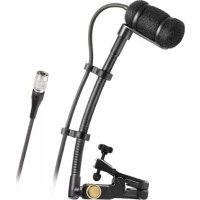
AT8468 Description
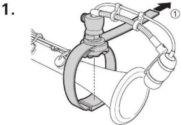
The violin mount fastens beneath the strings between the bridge and the tailpiece to provide outstanding pickup of violin and other stringed instruments.
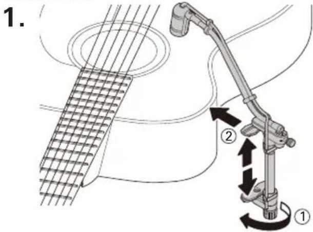
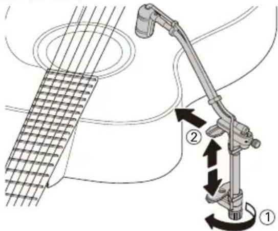
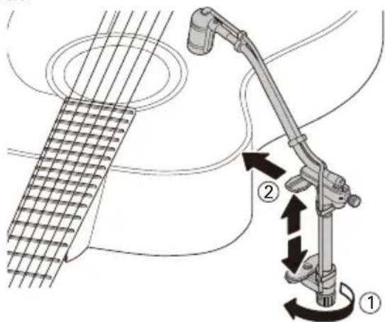
AT8491G Description
The guitar mount features a rugged, thumbscrew-adjustable clamp with pads that attaches to guitars and other stringed instruments while leaving fewer marks. You can adjust the clamp length between 90 mm (3.5") and 135 mm (5.3").
AT8491S Description
The surface mount is designed for accordions and other challenging applications. The notched mount can be attached permanently using the accordion's grille screw and the included adhesive silicon pad, or it can be attached temporarily using the included fastener tape pads. A transparent protective film is also included to prevent damage to the instrument's finish.
AT8475 Description
The surface mounting kit for AT8491S includes two adhesive silicon pads, two mount fastener tape pads, two surface fastener pads, and two transparent protective films.
Operation and Maintenance
The ATM350a requires 11V to 52V phantom power for operation.
Output is low impedance (Lo-Z) balanced. The signal appears across Pins 2 and 3; Pin 1 is ground (shield). Output phase is "Pin 2 hot" — positive acoustic pressure produces positive voltage at Pin 2.
To avoid phase cancellation and poor sound, all mic cables must be wired consistently: Pin 1 to Pin 1, etc.
The 80-Hz low-cut filter switch on the AT8543 power module makes it easy to switch from flat frequency response to low-frequency roll-off. This minimizes pickup of undesired low-frequency noise, such as from air conditioning systems. To engage the high-pass filter, slide the switch toward the "bent" line.
Avoid leaving the microphone in the open sun or in areas where temperatures exceed 110^ F ( 43^ C) for extended periods. Extremely high humidity should also be avoided.
User Manual / Accessories
Packages
ATM350U :
ATM350a, AT8490, AT8491U, AT8543, AT8468, hard shell carry case
ATM350UL :
ATM350a, AT8490L, AT8491U, AT8543, AT8468, hard shell carry case
ATM350PL :
ATM350a, AT8490L, AT8491P, AT8543, AT8468, hard shell carry case
ATM350W :
ATM350a, AT8490, AT8491W, AT8543, AT8468, hard shell carry case
ATM350D :
ATM350a, AT8490, AT8491D, AT8543, AT8468, hard shell carry case
ATM350GL :
ATM350a, AT8490L, AT8491G, AT8543, AT8468, hard shell carry case
ATM350S, ATM350SL :
ATM350a, AT8490 (ATM350SL: AT8490L), AT8491S, AT8475, AT8543, AT8468, hard shell carry case
ATM350UcW :
ATM350acW, AT8490, AT8491U, AT8468, hard shell carry case
ATM350UcH :
ATM350acH, AT8490, AT8491U, AT8468, hard shell carry case
DISCLAIMER
This product is designed to be used as a removable microphone mount on various musical instruments. When used properly, this product will not harm the finish or otherwise damage instruments. As a precaution, however, this product should not be left on an instrument indefinitely, and, ideally, should be removed after each use. Audio-Technica shall not be responsible or liable for any damages caused to a musical instrument as a result of using this product.
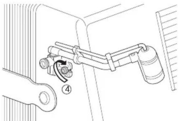
Mounting the microphone
AT8490/AT8490L
Gooseneck (standard/long)
text_image
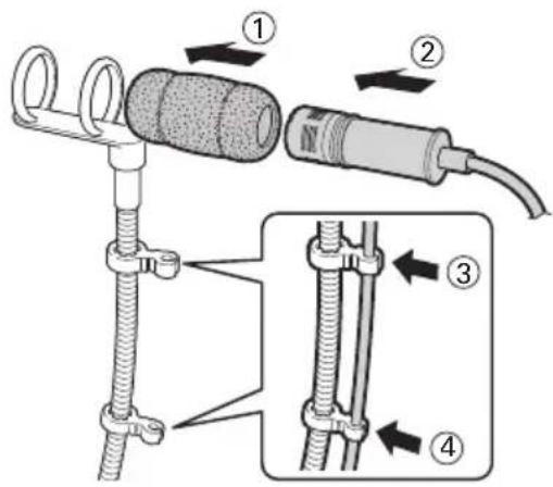
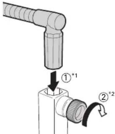
Diagram showing four steps of a cable installation with labeled components and directional arrows indicating sequence.Fixing the gooseneck on the mounts
text_image
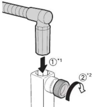
Diagram showing a mechanical assembly with labeled parts and directional arrows indicating motion or transformation.- The gooseneck can be fixed at every 90^ angle.
*1 Insert the gooseneck until it reaches the bottom of the hole on the mount. Firmly tighten the screw on the mount to secure it.
*2 Do not force the screw if there are any foreign objects in the way. Do not use any tools to tighten the screw. Doing so could strip the threads or damage the screw.
Setting the mounts on instruments
AT8491U
Universal clip-on mount

text_image
Diagram illustrating a hairdryer setup with labeled parts and directional arrows indicating movement or force.- To prevent damage to the instrument, take care not to tighten the screw excessively.
AT8491P
Piano mount
natural_image
Line drawing of a grand piano with a close-up inset showing a pipe being inserted into a tank (no text or symbols)- The mount should be fixed on a metal surface. Keep mobile phones, analog clocks and magnetic cards etc. away from the magnet in the bottom of the mount to prevent content from being damaged or erased.
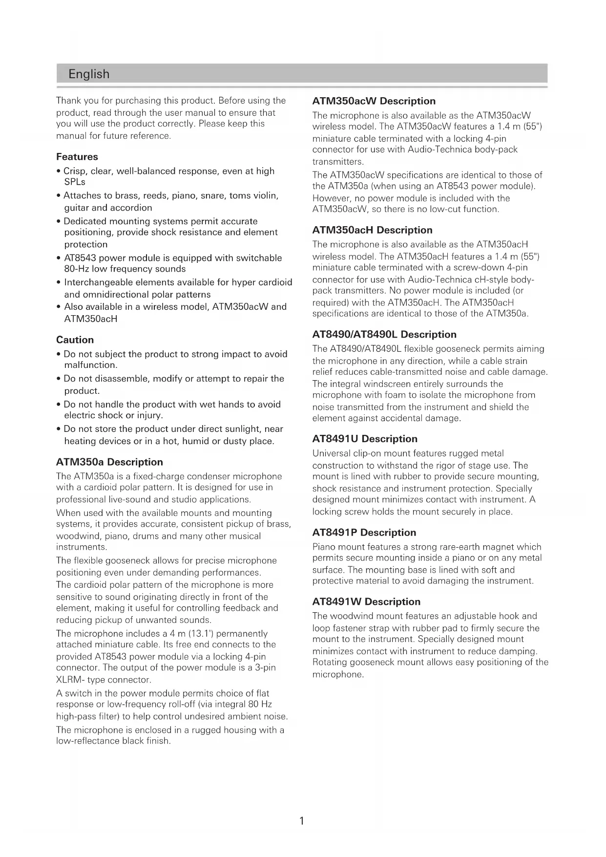
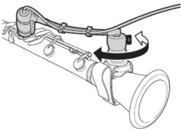
AT8491W
Woodwind mount
natural_image
Mechanical assembly diagram showing a pipe connection with hoses and a valve (no text or labels)
text_image
2. ③ ②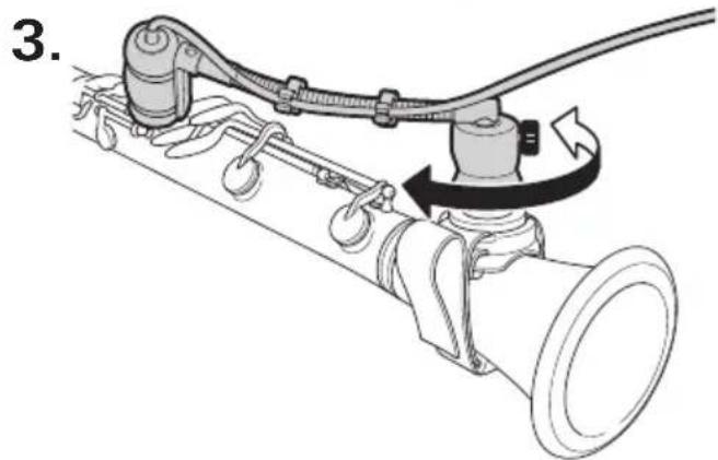
natural_image
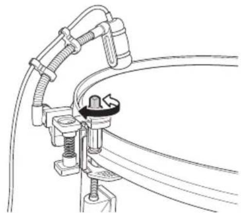
Mechanical diagram showing a pipe connection with hoses and a rotating lever (no text or symbols)- Adjust the position of the microphone by rotating the top of the mount.
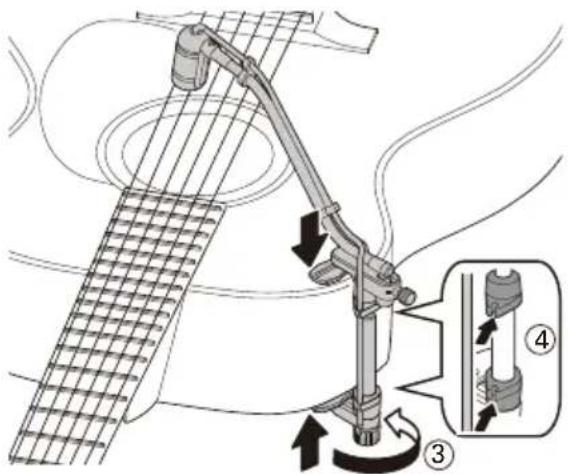
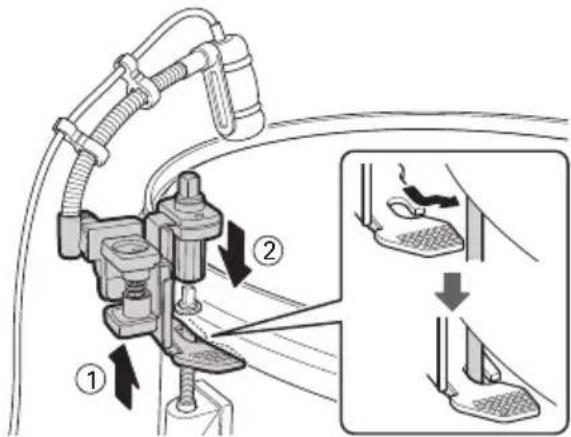
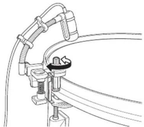
AT8491D
Drum mount
text_image
1. ① ②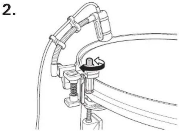
natural_image
Technical line drawing of a mechanical assembly with hoses and connectors (no text or symbols)- The top bolt rotates freely to allow tuning when the microphone is mounted.
AT8468
Violin mount

text_image
Technical diagram of a mechanical assembly with labeled parts and directional arrows indicating motion or movement.AT8491G
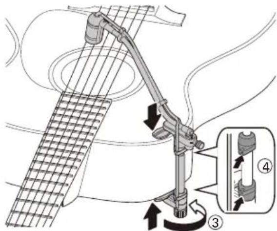
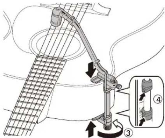
Guitar mount
text_image
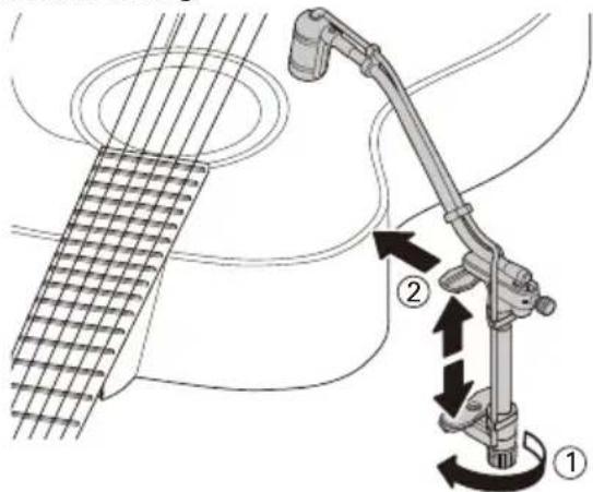
1. ① ②
text_image
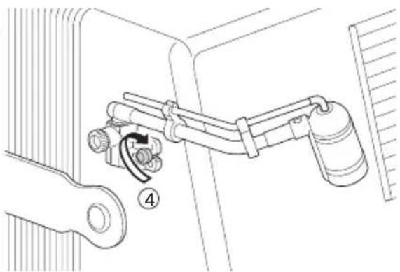
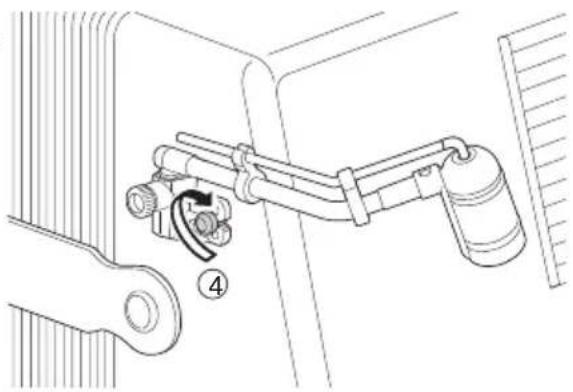
2. ③ ④- Rotate the screw and adjust the length, and then tighten the screw to secure in place.
- To prevent damage to the instrument, take care not to tighten the screw excessively.
AT8491S
Surface mount
- When using the grill fastening screw on the accordion. Depending on the shape of the screw, it may not be possible to install in this way.

text_image
1. ① ③ ②
text_image
2. ④- Affix the adhesive silicon pad to the back side of the mount. Loosen the grill fastening screw on the accordion, insert the mount, and then tighten the grill fastening screw to secure in place.
AT8491S
Surface mount
- When using surface fasteners
text_image
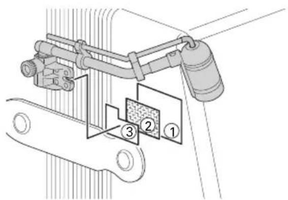
Technical diagram of a mechanical assembly with numbered components, likely illustrating a valve or actuator mechanism.- Affix the transparent protective film (①) to the body of the instrument, and affix a surface fastener tape pad (②) on top of that. Also affix a mount fastener tape pad (③) to the back side of the mount, and then affix it to the surface fastener on the body of the instrument to secure in place.
- Affix the transparent protective film on a clean, flat surface so that air bubbles do not form.
- You cannot affix the transparent protective film on unfinished wooden parts.
- To stabilize the adhesive strength of the adhesive sides of the surface and mount fasteners (②, ③), let them sit for about a day after affixing them before using the mount.
Specifications
| Element Fixed-charge back plate, permanently polarized condenser | |
| Polar pattern Cardioid | |
| Frequency response 40 - 20,000 Hz | |
| Low frequency roll-off 80 Hz, 12 dB/octave | |
| Open circuit sensitivity -49 dB (3.5mV) (0dB=1V/Pa, 1 kHz) | |
| Impedance 200 ohms | |
| Maximum input sound level 159 dB SPL (1 kHz THD 1%) | |
| Dynamic range 130 dB (1 kHz at Max SPL) | |
| Signal-to-noise ratio 65 dB (1 kHz at 1Pa, A-weighted) | |
| Phantom power requirements 11 - 52 V DC, 3.5 mA | |
| Switch* Flat, roll-off | |
| Weight Microphone: 14.5 g (0.5 oz), Power module: 90 g (3.2 oz) | |
| Dimensions | Microphone: 37.8 mm (1.49") long, 12.2 mm (0.48") diameterPower module: 92 mm (3.62") long, 18.9 mm (0.74") diameter |
| Output connector Power module: Integral 3-pin XLRM-type | |
| Cable(s) | 4.0 m (13.1') long (permanently attached to microphone), 3.2 mm (0.13") diameter, 2-conductor shielded cable with HIROSE HR10-type connector |
| Optional interchangeable elements UE-O omnidirectional, UE-H hypercardioid | |
| Accessories | AT8543 power module, microphone instrument mount, AT8468 violin mount, hard shell carry case |
- Characteristic weighting measured when connected to an AT8543 power module.
- 1 Pascal = 10 dynes/cm ^2 = 10 microbars = 94 dB SPL
- For product improvement, the product is subject to modification without notice.
* Mounted on an AT8543 power module.
Polar pattern

radar
| Angle | Value | |-------|-------| | 0° | High | | 30° | Medium| | 60° | Low | | 90° | Medium| | 120° | Low | | 150° | Medium| | 180° | Low | | 210° | Medium| | 240° | Low | | 270° | Medium| | 300° | Low | | 330° | High |LEGEND

SCALE IS 5 DECIBELS PER DIVISION
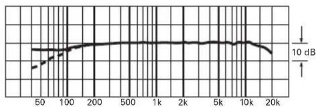
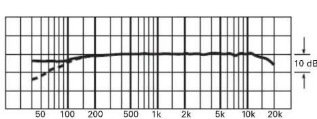
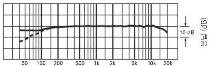
Frequency response
40–20,000 Hz
line
| x | y | | ---- | ----- | | 50 | ~0.8 | | 100 | ~1.0 | | 200 | ~1.1 | | 500 | ~1.1 | | 1k | ~1.1 | | 2k | ~1.1 | | 5k | ~1.1 | | 10k | ~1.1 | | 20k | ~0.9 |Frequency in Hertz
Response in dB
LEGEND
| 0°, 50 cm | |
| Roll-off |
- Characteristic weighting measured when connected to an AT8543 power module.
Français
text_image
Diagram showing four steps of a cable installation with labeled components and directional arrows indicating sequence.text_image
Diagram showing a mechanical assembly with labeled parts and directional arrows indicating motion or transformation.text_image
Diagram illustrating a hairdryer setup with labeled parts and directional arrows indicating movement or force.natural_image
Line drawing of a grand piano with a close-up inset showing a mechanical device connected to a surface (no text or symbols)natural_image
Mechanical assembly diagram showing a pipe connection with hoses and a valve (no text or labels)
text_image
2. ③ ②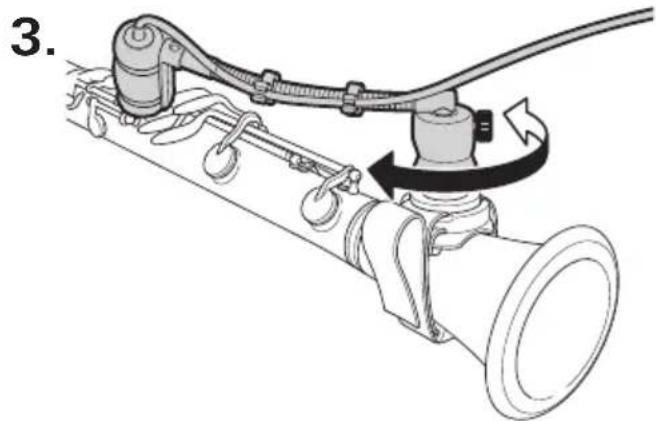
natural_image
Mechanical diagram showing a pipe connection with hoses and a valve, no text or symbols presentnatural_image
Technical line drawing of a mechanical clamp or bracket assembly (no text or symbols)text_image
Technical diagram showing mechanical assembly with labeled parts ① and ②, likely illustrating a valve or connector mechanism.AT8491G
text_image
Technical diagram of a mechanical assembly with numbered components, likely illustrating a valve or actuator mechanism.radar
| Angle | Value | |-------|-------| | 0° | High | | 30° | Medium| | 60° | Low | | 90° | Medium| | 120° | Low | | 150° | Medium| | 180° | Low | | 210° | Medium| | 240° | Low | | 270° | Medium| | 300° | Low | | 330° | High |LÉGENDE

ÉCHELLE DE 5 DÉCIBELS PAR DIVISION
text_image
Diagram showing four steps of a cable installation with labeled components and directional arrows indicating sequence.text_image
Diagram showing a mechanical assembly with labeled parts and directional arrows indicating motion or transformation.text_image
Diagram illustrating a medical procedure for catheter insertion, labeled with steps ① and ②.natural_image
Line drawing of a grand piano with an inset showing a mechanical device connected to a surface (no text or symbols)natural_image
Mechanical assembly diagram showing a pipe connection with hoses and a valve (no text or labels)
text_image
2. ③ ②
natural_image
Mechanical diagram showing a pipe connection with hoses and a valve, no text or symbols presentnatural_image
Technical line drawing of a mechanical clamp or bracket assembly (no text or symbols)text_image
Technical diagram showing mechanical assembly with labeled parts and directional arrows indicating motion or forceAT8491G
Gitarrenhalterung
1.
text_image
Diagram illustrating guitar mode shift and rotation process with labeled parts ①, ②, and directional arrows2.

text_image
Diagram illustrating guitar seatbelt mechanism with labeled parts and directional arrowstext_image
Technical diagram of a mechanical assembly with numbered components and directional arrows indicating motion or movement.2.
natural_image
Mechanical assembly diagram showing a linkage mechanism with no visible text or symbolstext_image
Technical diagram of a mechanical assembly with numbered components, likely illustrating a valve or clamp mechanism.radar
| Angle | Value | |-------|-------| | 0° | High | | 30° | Medium| | 60° | Low | | 90° | Medium| | 120° | Low | | 150° | Medium| | 180° | Low | | 210° | Medium| | 240° | Low | | 270° | Medium| | 300° | Low | | 330° | High |LEGENDE

SKALA VON 5 DEZIBEL PRO DIVISION
Frequenzgang
40–20,000 Hz

line
| x | y | | ---- | ----- | | 50 | ~0.8 | | 100 | ~1.0 | | 200 | ~1.1 | | 500 | ~1.1 | | 1k | ~1.1 | | 2k | ~1.1 | | 5k | ~1.1 | | 10k | ~1.1 | | 20k | ~0.9 |Frequenz in Hertz
Frequenzgang in dB
LEGENDE
| 0°, 50 cm | |
| Low-Cut |
text_image
Diagram showing four steps of a cable installation with labeled components and directional arrows indicating sequence.text_image
Diagram showing a mechanical assembly with labeled parts and directional arrows indicating motion or transformation.text_image
Diagram illustrating a hairdryer setup with labeled parts and directional arrows indicating motion or movement.natural_image
Line drawing of a grand piano with an inset showing a mechanical device connected to a surface (no text or symbols)natural_image
Mechanical assembly diagram showing a pipe connection with hoses and a valve (no text or symbols)
text_image
2. ③ ②
natural_image
Mechanical diagram showing a pipe connection with hoses and a rotating lever (no text or symbols)natural_image
Technical line drawing of a mechanical clamp or bracket assembly (no text or symbols)text_image
Technical diagram of a mechanical assembly with labeled parts and directional arrows indicating motion or force.AT8491G
text_image
Technical diagram of a mechanical assembly with numbered components, likely a valve or clamp mechanism.radar
| Angle | Value | |-------|-------| | 0° | High | | 30° | Medium| | 60° | Low | | 90° | Medium| | 120° | Low | | 150° | Medium| | 180° | Low | | 210° | Medium| | 240° | Low | | 270° | Medium| | 300° | Low | | 330° | High |LEGENDA

SCALA DI 5 DECIBEL PER DIVISIONE
text_image
Diagram showing four steps of a cable installation with labeled components and directional arrows indicating sequence.text_image
Diagram showing a mechanical assembly with labeled parts and directional arrows indicating motion or transformation.text_image
Diagram illustrating a hairdryer setup with labeled parts and directional arrows indicating movement or force.natural_image
Line drawing of a grand piano with a close-up inset showing a mechanical device connected to a surface (no text or symbols)natural_image
Mechanical assembly diagram showing a pipe connection with hoses and a valve (no text or symbols)
text_image
2. ③ ②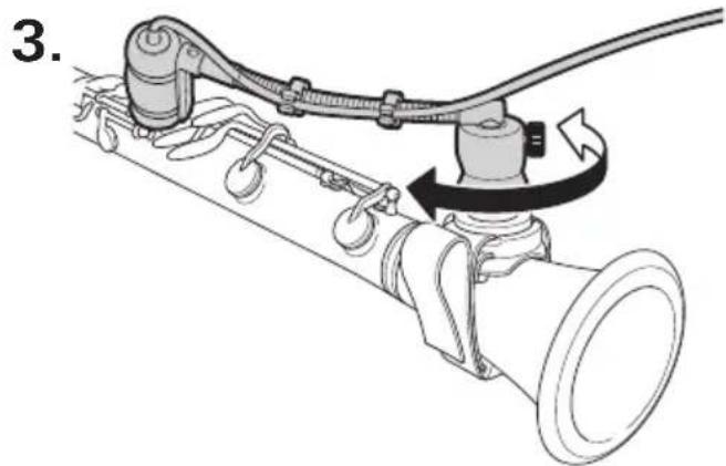
natural_image
Mechanical diagram showing a pipe connection with hoses and a rotating valve (no text or symbols)natural_image
Technical line drawing of a mechanical clamp or bracket assembly (no text or symbols)text_image
Technical diagram of a mechanical assembly with labeled parts ① and ②, showing connections and motion indicators.AT8491G
text_image
Technical diagram showing mechanical assembly with numbered components and labeled partsradar
| Angle | Value | |-------|-------| | 0° | High | | 30° | Medium| | 60° | Low | | 90° | Medium| | 120° | Low | | 150° | Medium| | 180° | Low | | 210° | Medium| | 240° | Low | | 270° | Medium| | 300° | High | | 330° | High |LEYENDA
text_image
Diagram showing four steps of a cable installation with labeled components and directional arrows indicating sequence.text_image
Diagram showing a mechanical assembly with labeled parts and directional arrows indicating motion or transformation.text_image
Diagram illustrating a hairdryer setup with labeled parts and directional arrows indicating movement or force.natural_image
Line drawing of a grand piano with a close-up inset showing a mechanical device connected to a surface (no text or symbols)natural_image
Mechanical assembly diagram showing a linkage mechanism with no visible text or symbols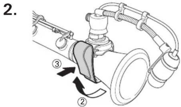
text_image
2. ③ ②
natural_image
Mechanical diagram showing a pipe connection with hoses and a rotating valve (no text or symbols)natural_image
Technical line drawing of a mechanical clamp or bracket assembly (no text or symbols)text_image
Technical diagram showing mechanical assembly with labeled parts ① and ②, likely illustrating a valve or connector mechanism.AT8491G
Suporte de violão
1.
text_image
Diagram illustrating guitar mode shift and rotation process with labeled parts ①, ②, and directional arrows2.

text_image
Diagram illustrating guitar seatbelt mechanism with labeled parts and directional arrowstext_image
Technical diagram of a mechanical assembly with numbered components and directional arrows indicating motion or movement.2.

natural_image
Mechanical assembly diagram showing a linkage mechanism with no visible text or symbolstext_image
Technical diagram showing mechanical assembly with numbered components and labeled partsradar
| Angle | Value | |-------|-------| | 0° | High | | 30° | Medium| | 60° | Low | | 90° | Medium| | 120° | Low | | 150° | Medium| | 180° | Low | | 210° | Medium| | 240° | Low | | 270° | Medium| | 300° | Low | | 330° | High |LEGENDA

text_image
Diagram showing four steps of a cable installation or mounting procedure with labeled components and directional arrows.text_image
Diagram showing a mechanical assembly with labeled parts and directional arrows indicating motion or movement.text_image
Diagram illustrating a medical procedure involving a device with labeled steps ① and ②, showing fluid flow or mechanical components.natural_image
Line drawing of a grand piano with a close-up inset showing a coiled instrument being inserted into a pool (no text or symbols)natural_image
Mechanical assembly diagram showing a linkage mechanism with hoses and a central pipe (no text or symbols)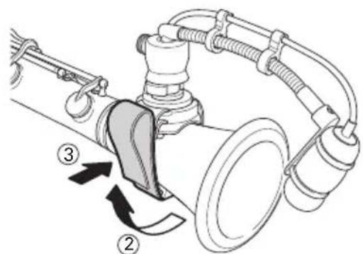
text_image
Technical diagram of a mechanical device with labeled parts and directional arrows indicating motion or assembly.
natural_image
Technical diagram of a mechanical assembly with hoses and rotating components (no text or symbols)text_image
Diagram illustrating foot movement and foot positioning on a car, with labeled parts and directional arrows2.
natural_image
Technical line drawing of a mechanical assembly with hoses and connectors (no text or symbols)text_image
Technical diagram of a mechanical assembly with labeled parts ① and ②, showing connections and motion indicators.AT8491G
text_image
Diagram illustrating the use of a guitar to interact with a keyboard, labeled with numbered instructions.2.
text_image
Diagram illustrating guitar seatbelt mechanism with labeled parts and directional arrowstext_image
Technical diagram showing mechanical assembly with numbered components and directional arrows indicating motion or movement.2.

natural_image
Mechanical assembly diagram showing a lever mechanism with labeled parts (no text or symbols present)text_image
Technical diagram showing mechanical assembly with numbered components, likely a valve or connector assembly.radar
| Angle | Value | |-------|-------| | 0° | High | | 30° | Medium| | 60° | Low | | 90° | Medium| | 120° | Low | | 150° | Medium| | 180° | Low | | 210° | Medium| | 240° | Low | | 270° | Medium| | 300° | Low | | 330° | High |text_image
Diagram showing four steps of a cable installation with labeled components and directional arrows indicating movement.在支架上固定鹅颈曲管
text_image
Diagram showing a mechanical assembly with labeled parts and directional arrows indicating motion or transformation.text_image
Diagram illustrating a hairdryer setup with labeled parts and directional arrows indicating movement or force.natural_image
Line drawing of a grand piano with a close-up inset showing a coiled instrument being inserted into a basin (no text or symbols present)· 支架应固定在金属表面上。
natural_image
Mechanical assembly diagram showing a linkage mechanism with hoses and a central component (no text or symbols)
text_image
Technical diagram of a mechanical device with labeled parts and directional arrows indicating motion or assembly.
natural_image
Technical diagram of a mechanical assembly with hoses and tubing, showing rotational motion (no text or labels)text_image
Diagram illustrating foot movement and foot positioning on a car, with labeled parts and directional arrows2.

natural_image
Technical line drawing of a mechanical assembly with hoses and connectors (no text or symbols)text_image
Technical diagram of a mechanical assembly with labeled parts and directional arrows indicating motion or force.AT8491G
吉他支架
1.

text_image
Diagram illustrating the use of a guitar to interact with a keyboard, showing labeled parts and directional arrows.2.

text_image
Diagram illustrating guitar seatbelt mechanism with labeled parts and directional arrowstext_image
Technical diagram of a mechanical assembly with numbered components and directional arrows indicating motion or movement.2.

natural_image
Mechanical assembly diagram showing a lever mechanism with labeled parts (no text or symbols present)text_image
Technical diagram showing mechanical assembly with labeled components 1, 2, and 3radar
| Angle | Value | |-------|-------| | 0° | High | | 30° | Medium| | 60° | Low | | 90° | Medium| | 120° | Low | | 150° | Medium| | 180° | Low | | 210° | Medium| | 240° | Low | | 270° | Medium| | 300° | Low | | 330° | High |图例
比例是每分隔线5分贝
频率响应
40–20,000 Hz
line
| Frequency | Value | | --------- | ----- | | 50 | ~0.8 | | 100 | ~0.9 | | 200 | ~0.95 | | 500 | ~0.95 | | 1k | ~0.95 | | 2k | ~0.95 | | 5k | ~0.95 | | 10k | ~0.95 | | 20k | ~0.85 |响应单位是 dB
频率单位是赫兹
图例
| 0°,50cm | |
| 滚降 |
text_image
Diagram showing four steps of a cable installation with labeled components and directional arrows indicating sequence.將鵝頸管固定在支架上

text_image
Diagram showing a mechanical assembly with labeled parts and directional arrows indicating motion or transformation.text_image
Diagram illustrating a hairdryer setup with labeled parts and directional arrows indicating movement or force.natural_image
Line drawing of a grand piano with an inset showing a pipe being inserted into a basin (no text or symbols present)· 支架應固定在金屬表面上。
natural_image
Mechanical assembly diagram showing a linkage mechanism with hoses and a central component (no text or symbols)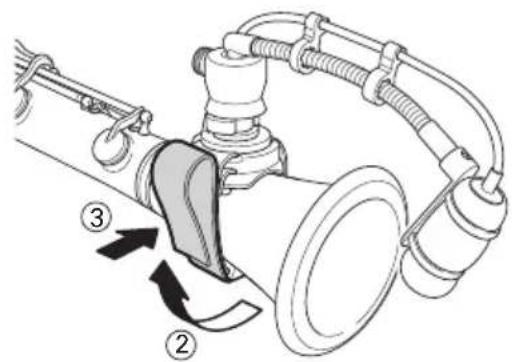
text_image
Technical diagram of a mechanical device with labeled parts and directional arrows indicating motion or assembly.
natural_image
Technical diagram of a mechanical assembly with rotating components and connecting rods (no text or labels)· 旋轉支架頂部即可調整麥克風位置。
AT8491D
鼓支架
text_image
Diagram illustrating foot push technique with labeled parts and step-by-step instructions2.

natural_image
Technical line drawing of a mechanical clamp or bracket assembly (no text or symbols)text_image
Technical diagram of a mechanical assembly with labeled parts and directional arrows indicating motion or force.AT8491G
吉他支架
1.
text_image
Diagram illustrating the use of a guitar to interact with a keyboard, showing labeled parts and directional arrows.2.
text_image
Diagram illustrating guitar seatbelt mechanism with labeled parts and directional arrowstext_image
Technical diagram of a mechanical assembly with numbered components and directional arrows indicating motion or movement.2.

natural_image
Mechanical assembly diagram showing a lever mechanism with labeled parts (no text or symbols present)text_image
Technical diagram showing mechanical assembly with labeled components 1, 2, and 3radar
| Angle | Value | |-------|-------| | 0° | High | | 30° | Medium| | 60° | Low | | 90° | Medium| | 120° | Low | | 150° | Medium| | 180° | Low | | 210° | Medium| | 240° | Low | | 270° | Medium| | 300° | Low | | 330° | High |圖例

比例尺為每刻度5分貝
頻率響應
40-20,000 Hz
line
| x | y | | ---- | ----- | | 50 | ~0.8 | | 100 | ~0.9 | | 200 | ~0.95 | | 500 | ~0.95 | | 1k | ~0.95 | | 2k | ~0.95 | | 5k | ~0.95 | | 10k | ~0.95 | | 20k | ~0.85 |text_image
Diagram showing four steps of a cable installation with labeled components and directional arrows indicating sequence.마운트에 구즈넥 고정

text_image
Diagram showing a mechanical assembly with labeled parts and directional arrows indicating motion or transformation.text_image
Diagram illustrating a kitchen sink setup with labeled components and directional arrows indicating movement or flow.natural_image
Line drawing of a grand piano with a close-up inset showing a pipe being inserted into a basin (no text or symbols)natural_image
Mechanical assembly diagram showing a linkage mechanism with no visible text or symbols2.

text_image
Technical diagram of a mechanical device with labeled parts and directional arrows indicating motion or assembly.3.
natural_image
Technical diagram of a mechanical assembly with hoses and rotating components (no text or symbols)text_image
Diagram illustrating foot positioning and movement of a car interior, labeled with steps ①, ②, and directional arrows.2.
natural_image
Technical line drawing of a mechanical clamp or bracket assembly (no text or symbols)text_image
Technical diagram showing mechanical assembly with labeled parts ① and ②, likely illustrating a valve or connector mechanism.AT8491G
기타 마운트
1.
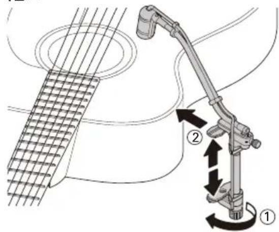
text_image
Diagram illustrating the use of a guitar stroke technique with labeled parts and directional arrows indicating motion.2.
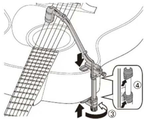
text_image
Diagram illustrating guitar fretting mechanism with labeled parts and directional arrowstext_image
Technical diagram of a mechanical assembly with numbered components and directional arrows indicating motion or movement.2.
natural_image
Mechanical assembly diagram showing a lever mechanism with labeled parts (no text or symbols present)text_image
Technical diagram showing mechanical assembly with numbered components, likely a valve or connector assembly.radar
| Angle | Value | |-------|-------| | 0° | High | | 30° | Medium| | 60° | Low | | 90° | Medium| | 120° | Low | | 150° | Medium| | 180° | Low | | 210° | Medium| | 240° | Low | | 270° | Medium| | 300° | Low | | 330° | High |
구역당 5데시벨
주파수 응답
40-20,000 Hz
line
| Frequency | Output Voltage (dB) | | --------- | ------------------- | | 50 | ~0.8 | | 100 | ~0.9 | | 200 | ~0.95 | | 500 | ~0.98 | | 1k | ~0.99 | | 2k | ~0.99 | | 5k | ~0.99 | | 10k | ~0.98 | | 20k | ~0.9 |주파수(헤르츠)
범례
| 0°,50cm | |
| 물오프 |
(This warranty is valid only for products purchased and used in Japan.)
Warranty (Please be sure to read the notes below.) For USA Only
End-User LIMITED WARRANTY information for the USA is available at www.audio-technica.com/usawarranties. You may also contact Audio-Technica U.S., Inc. to request a written copy of the Limited Warranty at 1-330-686-2600 or via mail at 1221 Commerce Drive, Stow, OH 44224.
Audio-Technica Corporation
2-46-1 Nishi-naruse, Machida, Tokyo 194-8666, Japan
© 2018 Audio-Technica Corporation
Global Support Contact: www.at-globalsupport.com