
B020U0819IP - Switch Tripp Lite - Free user manual and instructions
Find the device manual for free B020U0819IP Tripp Lite in PDF.
| Product Type | Rack-mount Console KVM Switch with Built-in IP Access |
| Model | B020U0819IP (8 ports) |
| Dimensions (H x W x D) | 44 x 480 x 686 mm |
| Weight | 13.9 kg |
| Power Supply | 100-240 V, 50/60 Hz, 1 A |
| Power Consumption | 21 W (120 V/60 Hz) |
| Number of Computer Ports | 8 |
| Built-in Monitor | 48.3 cm (19") LCD Screen, Max Resolution 1280 x 1024 @ 75 Hz |
| Network Connectivity | RJ45, TCP/IP, IPv4/IPv6, HTTP/HTTPS, DHCP, SSL, etc. |
| Remote Access | Via Web Browser, Windows Client, Java Client |
| Security | 3 Levels (Admin, User, Select), TLS 1.2 Encryption, AES 256-bit, RADIUS/LDAP Authentication |
| Additional Ports | 1 Front USB 1.1 Port, 1 Front External Mouse Port, 1 Rear External Console |
| Daisy-Chain Connection | Up to 31 Switches, Up to 264 Computers |
| Maintenance | Clean with a damp cloth; unplug before cleaning; do not use liquid cleaners |
| Safety Instructions | Must be grounded; do not block ventilation; do not use near water; refer repairs to qualified personnel |
| Warranty | Limited 1-Year Warranty |
Frequently Asked Questions - B020U0819IP Tripp Lite
User questions about B020U0819IP Tripp Lite
0 question about this device. Answer the ones you know or ask your own.
Ask a new question about this device
Download the instructions for your Switch in PDF format for free! Find your manual B020U0819IP - Tripp Lite and take your electronic device back in hand. On this page are published all the documents necessary for the use of your device. B020U0819IP by Tripp Lite.
USER MANUAL B020U0819IP Tripp Lite
Console KVM Switch with IP Access
Models: B020-U08-19-IP, B020-U16-19-IP
Français 65
WARRANTY REGISTRATION
Register your product today and be automatically entered to win an ISOBAR ^® surge protector in our monthly drawing!
tripplite.com/warranty


1111 W. 35th Street, Chicago, IL 60609 USA • tripplite.com/support
Copyright © 2021 Tripp Lite. All rights reserved.
Table of Contents
1. FCC Information 3
2. User Notice 3
3. Package Contents 3
4. Introduction 3
4.1 Overview 3
4.2 Features 4
4.3 System Requirements 4
4.3.1 Optional External Console 4
4.3.2 Computers 4
4.3.3 Remote Console 4
4.3.4 Supported Browsers 4
4.3.5 Cables 4
4.3.6 Operating Systems 5
4.4 Components 5
4.4.1 Front View 5
4.4.2 Rear View 6
5. Installation 7
5.1 General Safety Instructions 7
5.2 Standard Rack Mounting 8
5.3 Grounding 8
5.4 LCD OSD Configuration 8
5.5 Single-Station Installation 9
5.6 Multiple Station (Daisy-Chained) Installation 9
5.7 Network Setup-IP Address Configuration 10
5.7.1 Local Console 10
5.7.2 IP Installer 10
5.7.3 Browser/Non-Browser Client 11
5.7.4 Changing the Super Administrator Login 11
6. KVM Operation 12
6.1 Sharing USB Peripheral Devices 12
6.2 Powering Off and Restarting 12
6.3 Local Console Login 12
6.4 Local Console Port Access 13
6.4.1 Local Console OSD Invocation Sequence 13
6.4.2 Local Console OSD Navigation 13
6.4.3 Local Console OSD Main Screen Headings 13
6.4.4 Local Console OSD F1 GOTO Function 13
6.4.5 Local Console OSD F5 Skip Function 13
6.4.6 Local Console OSD F6 Broadcast Mode (BRC) 14
6.4.7 Local Console OSD F7 Auto Scan Function 14
6.4.8 Local Console OSD F8 Logout Function 14
6.4.9 Local Console Pushbuttons 14
6.4.10 Local Console Hotkey Commands 14
6.5 Logging Into the KVM over IP 16
6.5.1 Browser Login 16
6.5.2 Windows Client Login 17
6.5.3 AP Java Client Login 18
6.6 Remote Session Operation 19
6.6.1 Control Panel 19
6.6.2 The OSD Toolbar 25
6.6.3 Auto Scanning 26
7. Administration 27
7.1 Local Console OSD 28
7.1.1 Local Console OSD F2 LIST Function 28
7.1.2 Local Console OSD F3 Settings (SET) Page 28
7.1.3 Local Console OSD F4 Administration 30
(ADM) Page
7.1.4 Local Console Firmware Upgrade 31
7.2 OSD Operation 32
7.2.1 OSD Main Page 32
7.2.2 OSD Tab Bar 33
7.2.3 Port Access 33
7.2.4 Connections 34
7.2.5 Favorites 37
7.2.6 User Preferences 38
7.2.7 Sessions 38
7.2.8 Access 39
7.2.9 Port Configuration 40
7.2.10 User Management 41
7.2.11 Device Management 44
7.2.12 Device Information 44
7.2.13 Operating Mode 44
7.2.14 Network 45
7.2.15 Advanced Network Management Settings 46
7.2.16 Security 52
7.2.17 Date/Time 55
7.2.18 Log 56
7.2.19 Maintenance 57
7.2.20 Download 58
7.3 Log Server 59
8. Specifications 62
8.1 OSD Default Settings 62
8.2 Keyboard Emulation 63
9. Warranty and Product Registration 64
1. FCC Information
This is an FCC Class A product. This device complies with part 15 of the FCC Rules. Operation is subject to the following two conditions: (1) This device may not cause harmful interference, and (2) this device must accept any interference received, including interference that may cause undesired operation.
Note: This equipment has been tested and found to comply with the limits for a Class A digital device, pursuant to part 15 of the FCC Rules. These limits are designed to provide reasonable protection against harmful interference when the equipment is operated in a commercial environment. This equipment generates, uses, and can radiate radio frequency energy and, if not installed and used in accordance with the instruction manual, may cause harmful interference to radio communications. Operation of this equipment in a residential area is likely to cause harmful interference in which case the user will be required to correct the interference at his own expense. The user must use shielded cables and connectors with this equipment. Any changes or modifications to this equipment not expressly approved by Tripp Lite could void the user's authority to operate this equipment.
2. User Notice
All information, documentation, and specifications contained in this manual are subject to change without prior notification by the manufacturer. The manufacturer makes no representations or warranties, either expressed or implied, with respect to the contents hereof and specifically disclaims any warranties as to merchantability or fitness for any particular purpose. Any of the manufacturer's software described in this manual is sold or licensed "as is." Should the programs prove defective following their purchase, the buyer (and not the manufacturer, its distributor, or its dealer), assumes the entire cost of all necessary servicing, repair and any incidental or consequential damages resulting from any defect in the software.
The manufacturer of this system is not responsible for any radio and/or TV interference caused by unauthorized modifications to this device. It is the responsibility of the user to correct such interference.
The manufacturer is not responsible for any damage incurred in the operation of this system if the correct operational voltage setting was not selected prior to operation. PLEASE VERIFY THAT THE VOLTAGE SETTING IS CORRECT BEFORE USE.
3. Package Contents
This package consists of:
- Console KVM Switch with Built-in IP
- 6 ft. USB/PS2 Combo KVM Cable Kits (x2)
• USB/PS2 Combo Console Cable Kit - Grounding Wire
• RJ11 to DB9 Firmware Upgrade Cable - Rack-Mount Hardware
• C13 to 5-15P Power Cord
• CD with Owner's Manual and Device Files
Check to make sure that all of the components are present and in good order. If anything is missing, or was damaged in shipping, contact your dealer.
Read this manual thoroughly and follow the installation and operation procedures carefully to prevent any damage to the switch or to any other devices on the installation.
4. Introduction

4.1 Overview
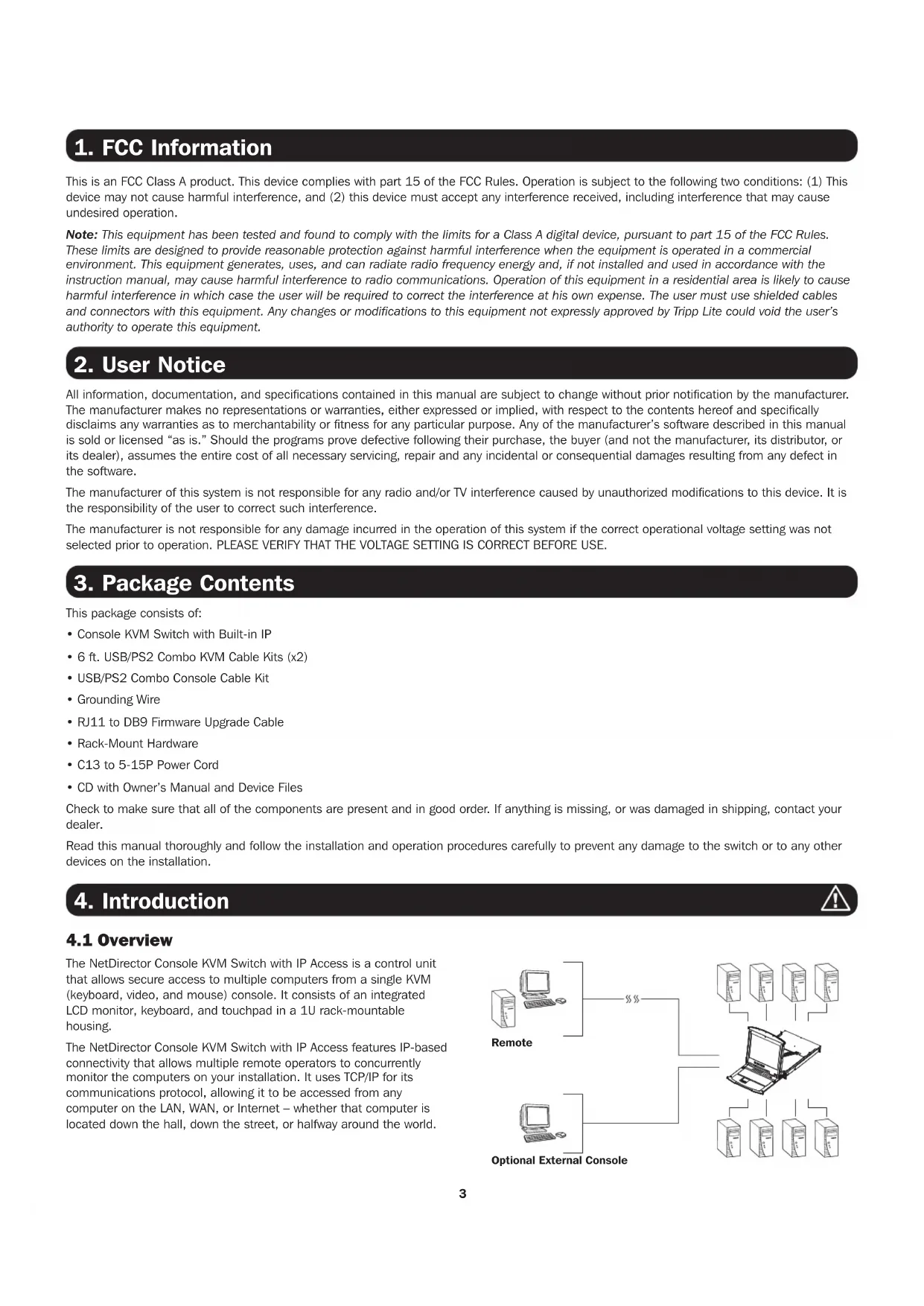
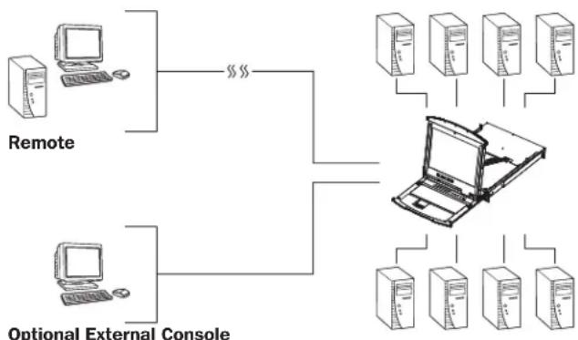
The NetDirector Console KVM Switch with IP Access is a control unit that allows secure access to multiple computers from a single KVM (keyboard, video, and mouse) console. It consists of an integrated LCD monitor, keyboard, and touchpad in a 1U rack-mountable housing.
The NetDirector Console KVM Switch with IP Access features IP-based connectivity that allows multiple remote operators to concurrently monitor the computers on your installation. It uses TCP/IP for its communications protocol, allowing it to be accessed from any computer on the LAN, WAN, or Internet – whether that computer is located down the hall, down the street, or halfway around the world.
flowchart
graph TD
    A["Remote"] --> B["Optional External Console"]
    C["Remote"] --> B
    D["Remote"] --> E["Laptop"]
    F["Remote"] --> E
    G["Remote"] --> E
    H["Remote"] --> E
4. Introduction (continued)
4.2 Features
- 1U Console KVM Switch with built-in IP access – integrated 19 in. LCD monitor, keyboard and touchpad.
- Connect either USB or PS/2 computers using P778-Series USB/PS2 Combo KVM Cable Kits – no need for separate cable kits.
- Control up to 8 (B020-U08-19-IP) or 16 (B020-U16-19-IP) computers on a single KVM switch.
- Daisy-chain up to 31 additional B020-U08 switches to connect up to 264 computers.
- Daisy-chained station position is automatically sensed—no need for manual DIP switch settings.
- Remotely access computers via LAN, WAN or Internet via the Windows™ or Java browser clients.
- AP Windows and Java Clients allow the KVM to be remotely accessed via the network without going through a browser.
- External USB 1.1 port allows USB peripheral devices to be shared among connected computers.
- Grayscale feature allows you to view remote sessions in black and white, reducing the amount of data traveling over the network and improving keyboard/mouse response time over IP.
- External console port on the back allows for an optional external monitor (VGA), keyboard (USB or PS/2) and mouse (USB or PS/2) to be connected.
-
An additional external USB port is conveniently located on the front of the keyboard panel for an optional external mouse.
-
Console lock enables the console to be locked in place when not in use, preventing it from sliding out of the rack.
- Web management interface, OSD and toolbars provide convenient, user-friendly operation.
- 3-level security (Admin, User and Select) – up to 64 accounts can be created.
- Panel Array Mode – remotely monitor multiple ports at the same time.
- Message board feature allows users who are logged in at the same time to communicate with each other and manage port access.
- CD includes a Windows-based log server that records events on the installation and writes them to a searchable database.
- Advanced encryption technologies: Supports TLS 1.2 data encryption and RSA 2048 bits certificates for secure user logins from a browser. Support 256-bit AES, 56-bit DES, 168-bit 3DES, 128-bit RC4 and 128-bit SSL.
• Supports RADIUS and LDAP/S authentication. - Flash firmware upgradable via network and included firmware upgrade cable.
• Supports both IPv4 and IPv6. - Supports Link Local IPv6 Address and IPv6 Stateless Auto configuration protocol.
• Network interfaces: TCP/IP, HTTP, HTTPS, RADIUS, DHCP, SSL, ARP, DNS, 10Base-T/100Base-TX, Auto Sense and Ping. - Supports video resolutions up to 1280 x 1024 @ 75 Hz (built-in monitor) and 1920 x 1080 @ 60 Hz (remote console).
4.3 System Requirements
4.3.1 Optional External Console 4.3.3 Remote Console
- A VGA, SVGA, or MultiSync monitor capable of displaying the highest resolution provided by any computer in the installation.
- PS/2 or USB keyboard and mouse.
4.3.2 Computers
The following equipment must be installed on each computer:
- A VGA, SVGA or MultiSync video graphics card with an HD15 port.
Note: The integrated LCD monitor's maximum resolution is 1280 x 1024 @ 75 Hz. Ensure that none of the computer resolution settings exceed the LCD monitor's maximum resolution.
Either:
- PS/2 mouse and keyboard ports (6-pin Mini-DIN).
-
USB port.
-
For best results, computers that remotely access the KVM switch should have at least a Pentium III 1 GHz processor.
- Use IE8 or above web browser
- Browsers must support TLS 1.2 encryption
- Users who want to access the KVM switch with the Windows Client must have DirectX 8.0 or higher installed.
- If you don't already have it, DirectX is available for free download from Microsoft's Website: http://www.microsoft.com/downloads.
- Users who want to access the KVM switch with the Java Client must have Sun's Java 2 v1.6 and higher, or directly change to The latest Java JRE. Java is available for free download from the Sun Java Website: http://java.sun.com.
- For best results, a network transfer speed of at least 512 Kbps is recommended.
4.3.4 Supported Browsers
| Browser Versions Supported | |
| Internet Explorer 8 and higher | |
| Firefox 1.5 and higher | |
| Mozilla | 1.7 and higher |
| Safari | 4.0 and higher |
| Opera | 9.0 and higher |
| Netscape | 8.1 and higher |
4.3.5 Cables
This KVM switch requires the following custom-wired premium cables:
| Function Tripp Lite Part | |
| To Connect a PS/2 or USB Computer to the KVM P778-Series PS/2 or USB Combo KVM Cable Kit | |
| Daisy-Chain Cables P772- Series Daisy-Chain Cables | |
4. Introduction (continued)
4.3.6 Operating Systems
Supported operating systems are shown in the table, below:
| Operating System Versions Supported | |
| Windows 2000 and higher | |
| Linux RedHat 7.1 and higher | |
| Linux SuSE 9.0 and higher | |
| Linux Mandriva (Mandrake) 9.0 and higher | |
| UNIX AIX 4.3 and higher | |
| Operating System Versions Supported | |
| UNIX Free BSD 4.2 and higher | |
| UNIX Sun Solaris 8 and higher | |
| Novell Netware 5.0 and higher | |
| Mac OS 9 and higher | |
| DOS 6.22 and higher | |
4.4 Components
4.4.1 Front View
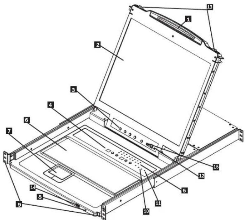
1Handle: Pull to slide the KVM module out; push to slide the KVM module in. (See item 13.)
2 LCD Monitor: After sliding the KVM module out, flip up the cover to access the LCD monitor.
3 LCD Controls: The LCD ON/OFF switch is located here, as well as buttons to control the position and picture settings of the LCD display.
4 Station/Port Switches: Press the Port ID Up/Down buttons to switch to the port before/after the currently selected port. Press the Station ID Up/Down buttons to switch to the station before/after the currently selected station.
5 LEDs: The Online Port LEDs illuminate orange to indicate a computer is connected and powered on. The Port ID LED will display the number of the port that currently has the console's focus. The Station ID LED will display the number of the station that currently has the console's focus.
6 Keyboard
7 Touchpad
8 Power LED: The Power LED illuminates blue to indicate the unit is receiving power.
9 Rack-Mount Tabs: The rack-mount tabs located at each corner of the unit secure the chassis to a system rack.
10 Lock LEDs: The Num Lock, Caps Lock and Scroll Lock LEDs are located here.
11 Reset Switch: Press this recessed switch in with a thin object to perform a system reset.
12 Firmware Upgrade Section: The firmware upgrade cable that transfers the firmware upgrade data from the administrator's computer to the console KVM switch connects to the port located here. During normal operation, this switch should be in the NORMAL position.
13 Slide Release: In order to bring the console out, you must first release it by sliding these tabs to the inside.
14 External Mouse Port: An additional USB port is provided on the front panel of the keyboard module for an option external mouse.
45 USB Peripheral Port: A USB 1.1 port is provided for the sharing of USB peripherals among connected computers (e.g. flash drive, CD-ROM drive, etc.).
4. Introduction (continued)
4.4.2 Rear View
Note: The B020-U08-19-IP model is shown in the below diagram. The B020-U16-19-IP model differs only in the number of KVM ports.
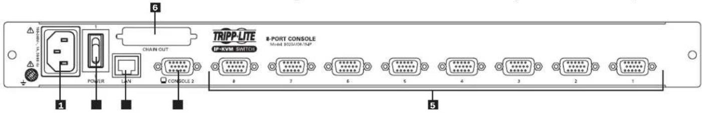
1 Power Socket: This is a standard C14 AC power socket. The power cord that comes with the unit plugs in here.
2 Power Switch: This is a standard rocker switch that powers the unit on and off.
3 External Console Port: The included USB/PS2 Combo Console Cable Kit connects to the KVM switch here, allowing you to attach an external VGA monitor and USB or PS/2 keyboard/mouse.
4 LAN Port: The cable that connects the KVM switch to a LAN, WAN, or Internet plugs in here.
5 KVM Ports: The custom wired KVM cable kits that connect to the computers plug in here.
Note: The shape of these connectors has been specifically modified to work only with Tripp Lite P778-Series USB/PS2 KVM Cable Kits.
6 Daisychain-Out Port
5. Installation
5.1 General Safety Instructions
- Read all of these instructions. Save them for future reference.
- Follow all warnings and instructions marked on the device.
- Do not place the device on any unstable surface (cart, stand, table, etc.). If the device falls, serious damage will result.
- Do not use the device near water.
- Do not place the device near, or over, radiators or heat registers.
- The device cabinet is provided with slots and openings to allow for adequate ventilation. To ensure reliable operation, and to protect against overheating, these openings must never be blocked or covered.
- The device should never be placed on a soft surface (bed, sofa, rug, etc.) as this will block its ventilation openings. Likewise, the device should not be placed in a built-in enclosure unless adequate ventilation has been provided.
- Never spill liquid of any kind on the device.
- Unplug the device from the wall outlet before cleaning. Do not use liquid or aerosol cleaners. Use a damp cloth for cleaning.
- The device should be operated from the type of power source indicated on the marking label. If you are not sure of the type of power available, consult your dealer or local power company.
- This device is designed for IT power distribution systems with up to 230V phase to phase voltage.
- The device is equipped with a 3-wire grounding type plug. This is a safety feature. If you are unable to insert the plug into the outlet, contact your electrician to replace your obsolete outlet. Do not attempt to defeat the purpose of the grounding-type plug. Always follow your local/national wiring codes.
- Do not allow anything to rest on the power cord or cables. Route the power cord and cables so that they cannot be stepped on or tripped over.
- If an extension cord is used with this device make sure that the total of the ampere ratings of all products used on this cord does not exceed the extension cord ampere rating. Make sure that the total of all products plugged into the wall outlet does not exceed 15 amperes.
- Consideration should be given to the connection of equipment to the supply circuit, and what effect overloading the supply circuit might have on overcurrent protection and supply wiring.
- To help protect your system from sudden, transient increases and decreases in electrical power, use a Tripp Lite Surge Protector, Line Conditioner, or Uninterruptible Power Supply (UPS).
- Position system cables and power cables carefully; be sure that nothing rests on any cables.
- When connecting or disconnecting power to hot pluggable power supplies, observe the following guidelines:
- Install the power supply before connecting the power cable to the power supply.
- Unplug the power cable before removing the power supply.
- If the system has multiple sources of power, disconnect power from the system by unplugging all power cables from the power supplies.
- Never push objects of any kind into or through cabinet slots. They may touch dangerous voltage points or short out parts resulting in a risk of fire or electrical shock.
- Do not attempt to service the device yourself. Refer all servicing to qualified service personnel. - If the following conditions occur, unplug the device from the wall outlet and bring it to qualified service personnel for repair:
- The power cord or plug has become damaged or frayed.
• Liquid has been spilled into the device.
• The device has been exposed to rain or water.
- The device has been dropped, or the cabinet has been damaged.
- The device exhibits a distinct change in performance, indicating a need for service.
- The device does not operate normally when the operating instructions are followed.
- Only adjust those controls that are covered in the operating instructions. Improper adjustment of other controls may result in damage that will require extensive work by a qualified technician to repair.
- Use of this equipment in life support applications where failure of this equipment can reasonably be expected to cause the failure of the life support equipment or to significantly affect its safety or effectiveness is not recommended. Do not use this equipment in the presence of a flammable anesthetic mixture with air, oxygen or nitrous oxide.
Rack Mounting Safety Instructions
- The ambient operating temperature in the rack may be an issue and is dependent upon the rack load and ventilation. When installing in a closed or multi-unit rack assembly, make sure that the temperature will not exceed the maximum rated ambient temperature.
- Before working on the rack, make sure that the stabilizers are secured to the rack, extended to the floor, and that the full weight of the rack rests on the floor. Install front and side stabilizers on a single rack or front stabilizers for joined multiple racks before working on the rack.
- Always load the rack from the bottom up, and load the heaviest item in the rack first.
- Always load the rack so that a hazardous condition is not created due to uneven loading.
- Make sure that the rack is level and stable before extending a device from the rack.
- Use caution when pressing the device rail release latches and sliding a device into or out of a rack; the slide rails can pinch your fingers.
- After a device is inserted into the rack, carefully extend the rail into a locking position, and then slide the device into the rack.
- Do not overload the AC supply branch circuit that provides power to the rack. The total rack load should not exceed 80 percent of the branch circuit rating.
- Ensure that proper airflow is provided to devices in the rack.
- Do not step on or stand on any device when servicing other devices in a rack.
- Do not connect the RJ11 connector marked "Upgrade" to a public telecommunication network.
- Caution! Slide/Rail (LCD KVM) mounted equipment is not to be used as a shelf or a work space.

CAUTION!
Slide/rail-mounted equipment is not to be used as a shelf or a workspace.
5. Installation (continued)
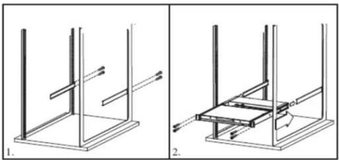
5.2 Standard Rack Mounting
The NetDirector Console KVM Switch with IP Access is designed for mounting in a 1U rack system. For convenience, a rack-mount kit is included with your console KVM switch for quick installation. The various mounting options are explained in the sections that follow.
Standard Rack Mounting
The standard rack mounting brackets that come attached to the console KVM switch allow the unit to be installed in a standard 1U rack by a single individual.
- Slide out the rear mounting brackets from the console and mount both brackets (separate from the console) to the inside rear of a standard 1U rack system using user-supplied screws.
- Take the console and gently slide it into the two rear-mounted brackets in the rack and secure the console in place by inserting user-supplied screws.
5.3 Grounding
To prevent damage to your installation it is important that all devices are properly grounded. Use the included grounding wire to ground the KVM switch by connecting one end of the wire to the grounding terminal on the unit, and the other end of the wire to a suitably grounded object.
5.4 LCD OSD Configuration
| The LCD Buttons | |
| The LCD OSD allows you to set up and configure the LCD display. Four buttons are used to perform the configuration, as described in the table below: | |
| Button Function | |
| MENU | When you have not entered the LCD OSD Menu function, pressing this button invokes the Menu function and brings up the Main Menu. |
| ▶|▲ | When navigating through the menus, this button moves you right or up. When making an adjustment, it increases the value. |
| ◀|▼ | When navigating through the menus, this button moves you left or down. When making an adjustment, it decreases the value. |
| EXIT | ·When you have not entered the LCD OSD Menu function, pressing this button performs an auto adjustment. An auto adjustment automatically configures all the settings for the LCD panel to what the OSD considers their optimum values to be. |
| ·When you have entered the LCD OSD Menu function, pressing this button exits the current menu and returns you to the previous menu. Use it to leave an adjustment menu when you are satisfied with the adjustment you have made. | |
| ·When you are at the Main Menu, pressing this button exits the LCD OSD. | |
2-Post Rack Mounting
The console KVM switch can also be mounted in a 2-post rack installation using the optional 2-Post Rack-Mount Kit (model #: B019-000). The mounting hardware allows for the console to be opened with the drawer in any position. Heavy-duty 14-gauge steel provides stability and prevents the console frame from twisting. See the B019-000 instructional manual for detailed mounting instructions.
natural_image
Technical line drawing showing two mechanical assembly steps: one with vertical supports and a horizontal bar, the other with a rectangular component inserted into a frame (no text or symbols)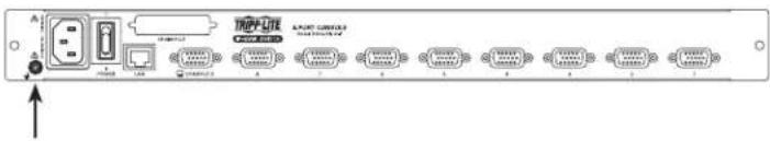
| The Adjustment Settings | |
| An explanation of the LCD OSD adjustment settings is given in the table below: | |
| Setting Explanation | |
| Brightness | Adjusts the background black level of the screen image. |
| Contrast | Adjusts the foreground white level of the screen image. |
| Phase Adjusts the vertical size of the screen image. | |
| Clock Adjusts the horizontal size of the screen image. | |
| H-Position | Positions the display area on the LCD panel horizontally (moves the display area left or right). |
| V-Position | Positions the display area on the LCD panel vertically (moves the display area up or down). |
| Color Temperature | Adjusts the color quality of the display. You can adjust the “warmth” value, color balance, etc. The Adjust Color selection has a further submenu that lets you fine tune the RGB values. |
| Language | Selects the language that the LCD OSD displays its menus in (English, French, German, Spanish or Italian). |
| OSD Duration | Lets you set the amount of time that the OSD displays on the screen. If there is no input for the amount of time you choose, the OSD display turns off. |
| Reset | Resets the menu and submenu adjustments (except for language settings) to the original factory default settings. |
5. Installation (continued)
5.5 Single-Station Installation
To set up your console KVM switch, refer to the following steps and installation diagram.
Note: The B020-U08-19-IP model is shown in the below diagram. The B020-U16-19-IP model differs only in the number of KVM ports.
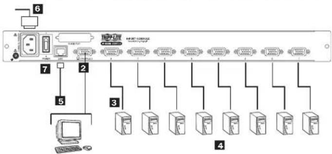
1 Power OFF all computers that are being connected to the KVM switch.
2 (Optional) Add an external console to the KVM by connecting the included USB/PS2 console cable kit to the console port on the back of the unit, and then connecting an external monitor (HD15), keyboard (USB or PS/2) and mouse (USB or PS/2) to the connectors on the cable kit. An additional USB port is located on the front keyboard panel of the unit as a more convenient alternative to the external mouse port on the back of the unit.
3 Connect a P778-Series USB/PS2 Combo KVM Cable Kit between an available KVM port on the back of the unit and a computer/server. P778-Series Cable Kits allow you to connect to a computer with either USB or PS/2* keyboard/mouse ports, without the need for separate cables. Note: The distance between the KVM and the connected computer must not exceed 33 ft. (10 m).
4 Repeat step 3 for each additional computer you wish to connect.
5 Connect the LAN port on the back of the unit to the network using Cat5e/6 cable.
6 Connect the included power cord to the C14 jack on the back of the unit, and then plug it into a Tripp Lite Surge Protector, PDU or Uninterruptible Power Supply (UPS).
7 First power ON the KVM switch, and then power on the connected computers.
*When connecting to computers using the PS/2 connectors of a P778-Series Cable Kit, the Mouse Sync Mode setting must be set to Manual in order to access the computer over IP. If Mouse Sync Mode is set to Automatic, you will not have mouse functionality when accessing that computer over IP. This setting is set to Manual by default. (See page 50 for details on changing this setting via the Web Management Interface, or page 40 to change it via the Remote OSD.)
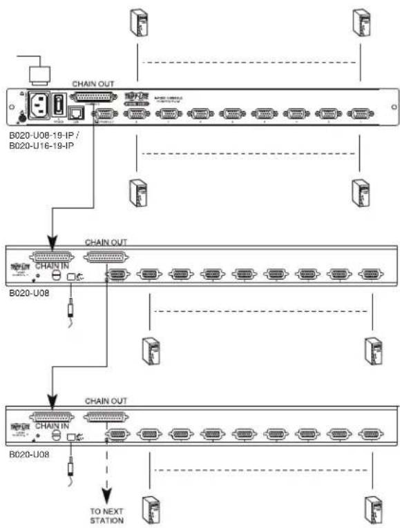
5.6 Multiple Station (Daisy-Chained) Installation
To control even more computers, up to 31 B020-U08 KVM Switches can be daisy-chained down from the first station.
Note: As many as 264 computers can be controlled from the unit's integrated console in a complete installation.
To set up a daisy-chained installation:
- Ensure that power to all the connected devices has been turned off.
- Connect the included USB/PS2 Combo Console Cable Kit to the console connector on the back of the unit, then connect a monitor, mouse and keyboard to the appropriate connectors on the cable kit. The distance between the external console and the KVM switch must not exceed 66 ft. (20 m).
- Use a daisy-chain cable (described in the Cables section) to connect the Chain Out port of the parent unit to the Chain In port of the child unit. The distance between any two KVM switches in a daisy-chain must not exceed 49 ft. (15 m). The distance between the first KVM switch and the last KVM switch in a daisy-chain must not exceed 328 ft. (100 m), regardless of the number of KVM switches in the entire chain.
- Use a KVM cable kit (described in the Cables section) to connect the keyboard, video and mouse ports of a computer to any available port on the KVM switch. The distance between the KVM switch and each connected computer must not exceed 33 ft. (10 m).
- Repeat the above steps for any additional KVM switches and computers you wish to add to the chain.
- To power up the installation:
a. Plug in the power adapter for the first station. Wait a few seconds to allow the unit to determine its Station ID.
b. Plug in the power adapters for each subsequent station in the installation (i.e. second station, third station, etc.). Each KVM switch has an LED display on its front panel to indicate its Station ID (the Station ID for the first station is 01, the ID for the second station is 02, the ID for the third station is 03, etc.).
In each case, wait for the Station ID to be displayed on the Station ID LED before plugging in the next station.
flowchart
graph TD
    A["BC020-U08-19-IP / BC020-U16-19-IP"] --> B["B020-U08"]
    B --> C["TO NEXT STATION"]
    D["B020-U08"] --> E["Switch"]
    F["B020-U08"] --> G["Switch"]
    H["B020-U08"] --> I["Switch"]
    J["B020-U08"] --> K["Switch"]
    L["B020-U08"] --> M["Switch"]
    N["B020-U08"] --> O["Switch"]
    P["Switch"] --> Q["Output"]
    R["Port 1"] --> S["Port 2"]
    T["Port 3"] --> U["Port 4"]
    V["Port 5"] --> W["Port 6"]
    X["Port 7"] --> Y["Port 8"]
    Z["Port 9"] --> AA["Port 10"]
5. Installation (continued)
5.7 Network Setup-IP Address Configuration
In order to configure a fixed IP address, you will need to access the KVM switch in one of three ways; Local Console, IP Installer or Browser.
5.7.1 Local Console
Note: The local console OSD only allows you to configure IPv4 network settings. For IPv6, access the Web Management Interface or Remote Session OSD.
- When accessing the console KVM switch for the first time, a prompt will appear asking for a Username and Password. The default Username is administrator, and the default Password is password. For security purposes, a "Change Password" prompt will appear requiring you to immediately change the password from the default. Please enter the old default password and then a new unique password in the remaining fields. It is strongly recommended that you also change the default Username to a unique one as well (see section 5.7.4 Changing the Super Administrator Login for details). Once you have successfully logged in and changed your password from the default, the Local OSD will appear with the following page displayed.
| F1:GOTO F3:SET F5:SKP F7:SCAN X | |||||
| F2:LIST F4:ADM F6:BRC F8:LOUT zZ^z | |||||
| ADMINISTRATOR LIST:ALL NAME | |||||
| SN.PN | QV | X | |||
| 02 - 14 | ABC COMP1 | ▲ | |||
| 02 - 15 | ◀ | X | ABC COMP2 | ↑ | |
| 02 - 16 | X | ABC COMP3 | |||
| 03 - 01 | WEB SERVER 1 | ||||
| 03 - 02 | WEB SERVER 2 | ||||
| 03 - 03 | ◀ | X | FAX SERVER 1 | ||
| 03 - 04 | X | FAX SERVER 2 | |||
| 03 - 05 | ◀ | X | MAIL SERVER 1 | ↓ | |
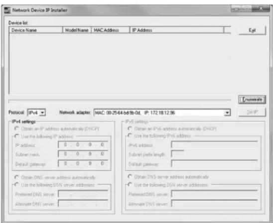
5.7.2 IP Installer
Computers that are running Windows can use the IP Installer utility found in the included CD to assign an IP address to the KVM.
Note: The IP Installer Settings section located in the Network page of the KVM's web management interface must be enabled in order to use the IP Installer to assign an IP address. (See page 42 for details.) This setting is enabled by default.
- Save the IP Installer.exe file from the CD to a desired location on a computer that is on the same network as the KVM switch.
- Locate the IP Installer.exe file that you just saved and double-click on it. A screen similar to the one below will appear:
- Press the [F4] key to bring up the OSD Admin page.
- In the OSD Admin page, highlight SET IP ADDRESS and press the [Enter] key.
- DHCP – The first field allows you to enable or disable DHCP. When enabled, the KVM is assigned an IP address by the DHCP server. This setting is enabled by default. To disable the DHCP setting and set up a fixed IP address, press the [Spacebar] key. Once the DHCP is disabled, you will be allowed to edit the remaining fields in the SET IP ADDRESS screen.
- In the remaining fields, enter in the IP address, subnet mask and default gateway you want to assign to the KVM switch.
-
Press the [Esc] key to exit the SET IP ADDRESS screen, and to pull up a prompt asking if you wish to save the settings you just entered. If you do not wish to save the settings, press the [N] key. If you do wish to save the settings, press the [Y] key. Upon pressing the [Y] key, the settings will be saved and the KVM will be reset.
-
The IP Installer searches the network and displays all B020-U08-19-IP and B020-U16-19-IP KVM Switches it finds in the device list. If your device does not show up in the list, click the Enumerate button to refresh the device list. If more than one of the same KVM switch models shows up in the list, locate the desired device using the Mac address located on the bottom of the console KVM. Once you have located your device in the list, highlight it.
- From here you can choose between the following two options: Obtain an IP address automatically (DHCP) or Specify an IP address. If you choose to assign your own address, fill in the IP Address, Subnet Mask, and Gateway fields with information appropriate to your network (IPv4 or IPv6). Click on the Set IP button to apply the new network settings to the selected KVM switch.
- After the new IP address shows up in the device list, click the Exit button to exit the IP Installer.
5. Installation (continued)
5.7.3 Browser/Non-Browser Client
By default, the KVM switch is set to have an IP address assigned automatically via DHCP server. If this is the case, you will need to obtain the IP address from your network administrator. If connected to a network without a DHCP server, it boots with a default IP address. The default IPv4 and IPv6 addresses can be found on the sticker on the bottom of the unit.
- Enter the unit's IP address into your web browser.
- You may be prompted by a screen stating that there is a problem with this website's security certificate. Click on the option to continue to the website anyway. (See Web Browser Login section for details on installing the security certificate)
- You will be brought to a login page. If logging in for the first time, enter the default Username (administrator) and the default Password (password). Once the default credentials have been entered, a "Change Password" prompt will appear, requiring you to immediately change the password from the default one. After the new password has been set, the Web Management Interface will open.
It is strongly recommended that you also change the default Username to a unique Username (see section 5.7.4 Changing the Super Administrator Login for details). - Click on the Device Management icon at the top of the page, then click Network in the subsections to open the Network settings page.
![Port Access User Management Device Management Log Maintenance Download TRIPP-LITE System Information Operating Node Network DNS Security Data/Time IP Provider Control User Only Controlled Service Ports Programs: 9000 Internet: 68 ADSPs: 443 DVA Settings IP Address: ○ Default IP address automatically [DNSP] ● Set IP address manually [Read IP] IP Address: 0.0.0.0 Subnet Name: 0.0.0.0 Default Gateway: 0.0.0.0 DNS Server: ○ Default DNS server address automatically ● Set DNS server address manually Preferred DNS server: 0.0.0.0 Alternate DNS server: 0.0.0.0 © 2017 TopPage All Rights Reserved](/content/2026/04/591621/images/19674377d590d142e08844a2cb093501b17849a2f81a366e0a37f2670fedb0ea.jpg)
- By default, the Obtain IP address automatically [DHCP] checkbox is checked. To set a fixed IP address, check the Set IP address manually [Fixed IP] check box in the IPv4 or IPv6 settings section, depending on your network.
- The IP Address, Subnet Mask and Default Gateway fields will be activated upon checking the Set IP address manually [Fixed IP] checkbox. Fill in these fields with information appropriate for your network.
- As with the IP Address settings, the DNS Server settings can be obtained automatically or assigned manually. To manually enter these settings, check the Set DNS server address manually checkbox and fill in the Preferred DNS server and Alternate DNS server fields with information appropriate for your network.
Note: The Alternate DNS server field is optional.
- When you have entered the IP Address and DNS Server settings, click the Save button. When you log out, the unit will be reset and your network changes will be applied.
See section 7.3.2 Network in this manual for complete information on the rest of the settings on this page.
5.7.4 Changing the Super Administrator Login
To change the default Super Administrator Username and Password, do the following:
- At the top of the OSD page, click User Management.
Since this is the first time the page is being accessed, only the Super Administrator appears:
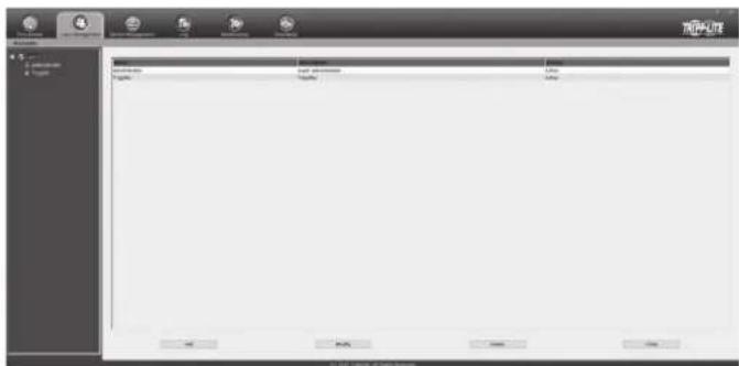
- Click Administrator in the left panel; or, select Administrator in the central panel and click the Modify button at the bottom of the page.
The User Information page appears:
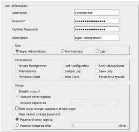
- Change the Username and Password to something unique.
- Re-enter the password to confirm it is correct.
- Click Save.
- When the dialog box informing you that the change completed successfully appears, click OK.
6. KVM Operation
Computers connected to the KVM switch can be accessed via the local console or over IP. This chapter discusses the basic operation of the KVM switch, both locally and remotely.
6.1 Sharing USB Peripheral Devices
The USB 1.1 port on the LCD panel of the console KVM switch can be used to share USB peripherals between connected computers. Simply connect a USB device to this port, and any connected computer you switch to will have access to the device. The USB peripheral sharing functionality works the same whether you are accessing the connected computers via the local console or over IP.
Note: The following limitations apply to the USB peripheral port:
- This port serves as a 1 port USB 1.1 hub; USB 2.0 devices can be connected, but will not function as designed.
- USB peripherals can only be shared among computers that are connected to the KVM switch via the USB connectors on the P778-Series USB/PS2 Combo KVM Cable Kit.
- USB peripherals can only be shared among computers that are connected to the KVM switch that the USB peripheral is plugged into. If a USB peripheral is plugged into the USB 1.1 port of the third KVM switch in a daisy-chain installation, only computers connected to that KVM can access the USB peripheral; computers connected to any other KVM in the installation will not be able to access the USB peripheral.
- When accessing a USB peripheral on a connected computer, it is recommended that you properly eject the device before switching to another computer. When switching computers, the device is automatically disconnected from the previous computer and connected to the next, as if it was manually unplugged from a USB port on one computer and then plugged into the USB port of another computer.
6.2 Powering Off and Restarting
If it becomes necessary to power off the KVM switch, follow this procedure:
- Shut down all computers connected to the KVM switch. If you are powering off multiple computers in a daisy-chain installation, shut down all computers connected to each KVM switch you are powering off.
Note: It is necessary to unplug any computers that have the Keyboard Power On function. If left on, the KVM switch will continue to receive power via these computers. - Turn off the KVM switch (console KVM only) and unplug the KVM switch from its power source. Power OFF and unplug each additional KVM switch in succession.
- Wait 10 seconds and then plug the KVM switch, starting with the first station, back into its power source. Turn on the power to the KVM switch (console KVM only).
- Once the first station KVM switch has ascertained its position in the daisy-chain, power on and plug in the next KVM switch in the installation. Follow this procedure for each additional KVM switch in the installation.
- Once all KVM switches in the installation have been powered back ON, turn on the power to all connected computers.
6.3 Local Console Login
When accessing the console KVM switch for the first time, a prompt will appear asking for a username and password. The default username is administrator, and the default password is password. For security purposes, a "Change Password" prompt will appear requiring you to immediately change the password from the default. It is strongly recommended that you also change the default username to a unique one as well (see section 5.7.4 Changing the Super Administrator Login for details). Once the KVM has been set up and user accounts have been created, the login prompt will only appear when a user logs out of the KVM. When you have entered your username and password, the OSD will appear with the following page displayed.
Note: When using the [Scroll Lock, Scroll Lock] OSD invocation sequence, you must hold down the [Fn] key, as the [Scroll Lock] key is part of the [Num Lock] key.
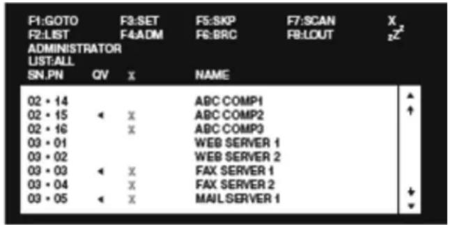
Note: 1) The diagram depicts the Administrator's Main Screen. The User Main Screen does not have the F4 and F6 functions, since they can't be accessed by ordinary Users and are reserved for the Administrator.
2) OSD always starts in List view, with the highlight bar at the same position it was when the OSD was last closed.
3) Only the ports that have been set accessible by the Administrator for the currently logged in User are visible.
4) If the port list is collapsed into stations, simply click on the plus sign next to the desired station number, or highlight the desired station number and hit the [Enter] key.
6. KVM Operation (continued)
6.4 Local Console Port Access
Once logged into the KVM, you can access connected computers via the local console using the Local Console OSD, Local Console Pushbuttons or Hotkey Commands. The following sections describe all of the ways in which you can access connected computers via the local console.
6.4.1 Local Console OSD Invocation Sequence
Once logged into the KVM switch and accessing a connected computer, you will need to use one of two sequences to re-open the OSD Main Menu; [Scroll Lock, Scroll Lock] or [Ctrl, Ctrl]. (See page 27 for details on changing this hotkey sequence.) The default OSD invocation sequence is [Scroll Lock, Scroll Lock].
6.4.2 Local Console OSD Navigation
When in the Local Console OSD, you can use your keyboard and mouse to access its features.
- To close out of the Local Console OSD, click the [X] at the upper right corner of the OSD or press the [Esc] key.
- To logout, press the [F8] key, click the F8 at the top of the OSD, or click the zzz symbol in the upper right hand corner of the OSD.
- To move through the OSD list one line at a time, click the up and down triangle symbols (▲,▼) or use the [↑] and [↓] keyboard keys. If there are more entries than appear on the screen, the screen will scroll.
- To move up or down one screen at a time, click the Up and Down Arrow symbols (↑,↓), or use the [Pg Up] and [Pg Dn] keyboard keys. If there are more entries than appear on the screen, the screen will scroll.
- To activate a port, double-click it, or highlight it and press the [Enter] key. Once a port is accessed, the OSD will close and the screen of the computer connected to the port will be displayed.
6.4.3 Local Console OSD Main Screen Headings
| SN | The Station Number of each KVM in the installation will be displayed in this column. The Station Number of each KVM switch will be displayed as an expandable folder, which can be expanded to show all of the KVM ports in the corresponding station, or collapsed to hide them. |
| PN | The port numbers of each KVM in the installation are displayed in this column. If the individual stations are collapsed, their port numbers will not be displayed. |
| QV An arrow | in this column indicates that the corresponding port is selected for Quick View scanning. |
| A sun symbol in this column indicates that a computer is both connected to the corresponding port and powered ON. | |
| NAME If a port has been given a name, its name appears in this column. | |
6.4.4 Local Console OSD F1 GOTO Function
Click F1 at the top of the OSD or press the [F1] key to activate the GOTO function. GOTO allows you to search the ports on the installation by keying in a Name or Port ID (see page 14 for details on Port IDs). As you type in a Name or Port ID, the OSD list will automatically display all ports in the installation that match your search terms. To access a port from the list, simply double-click on it or highlight it and press the [Enter] key. To exit GOTO mode and return to the OSD main page, press the [Esc] key.
- To search by Name, type [1] into the field that appears when the GOTO function is activated; a Name field will appear. Type in a name to display all accessible ports in the installation that match your entry.
- To search by Port ID, type [2] into the field that appears when the GOTO function is activated; a Port ID field will appear. Type in a port ID to display all accessible ports in the installation that match your entry.
6.4.5 Local Console OSD F5 Skip Function
Skip Mode allows connected computers to be accessed using the [] , [] , [] and [] keys on the keyboard. To invoke Skip Mode via the local console OSD, click F5 at the top of the OSD or press the [F5] key. When invoked, the KVM displays the screen of the last selected port, with a left/right triangle symbol next to the port's port ID to signify it is being accessed in Skip Mode. The ports accessed in Skip Mode are determined by the Scan Select setting in the F3 Set page of the local console OSD. (See SCAN/SKIP MODE on page 27 for details.) During Skip Mode, normal keyboard and mouse functionality is suspended. Keyboard functionality is limited to those keys mentioned in the table below. Mouse functionality is suspended altogether.
| Key Description | |
| [←] | Skips from the currently selected port to the next accessible port prior to it. |
| [→] | Skips from the currently selected port to the next accessible port after it. |
| [↑] | Skips from the currently selected port to the last accessible port on the previous station. |
| [↓] | Skips from the currently selected port to the first accessible port on the next station. |
| [Esc] Exits Skip Mode at the currently selected port. | |
| [Spacebar] Exits Skip Mode at the currently selected port. | |
6. KVM Operation (continued)
6.4.6 Local Console OSD F6 Broadcast Mode (BRC)
Broadcast Mode is an Administrator-ONLY function. Clicking the F6 at the top of the OSD or pressing the [F6] key invokes Broadcast Mode. When this function is in effect, commands sent from the console are broadcast to all available computers on the installation. This function is particularly useful for operations that need to be performed on multiple computers, such as performing a system-wide shutdown, installing or upgrading software, etc. Broadcast Mode works in conjunction with the F2 LIST function. The F2 LIST function (see page 26 for details) lets you select which ports will be displayed on the OSD main screen. When a command is broadcast, it is done only to the ports currently displayed on the OSD main screen.
- A speaker symbol appears before the Port ID Display to indicate Broadcast Mode is in effect.
- The mouse will not function while Broadcast Mode is in effect. You must exit Broadcast Mode in order to regain control of the mouse.
- To exit Broadcast Mode, invoke the OSD (with the OSD hotkey), and then click F6 at the top of the OSD or press the [F6] key.
6.4.7 Local Console OSD F7 Auto Scan Function
Auto Scan Mode allows connected computers to be accessed automatically at set time intervals. To invoke Auto Scan Mode via the local console OSD, click F7 at the top of the OSD or press the [F7] key. When invoked, the KVM begins scanning according to the Scan Select and Scan Duration settings in the F3 Set page of the local console OSD (see page 27 for details). During an auto scan, normal keyboard and mouse functionality is suspended. Keyboard functionality is limited to the [Spacebar] key (exits auto scan at the currently selected port), [Esc] key (exits auto scan at the currently selected port) and the [P] key (pauses auto scan at the currently selected port). Mouse functionality is suspended altogether.
6.4.8 Local Console OSD F8 Logout Function
To logout of the KVM switch, click on the F8 at the top of the page or press the [F8] key. You will be prompted to confirm that you wish to logout. Press the [Y] key if yes, or the [N] key if no. When logged out, the username and password screen will appear, requiring a username and password to be entered to access the KVM.
6.4.9 Local Console Pushbuttons
In addition to using the local console OSD to access connected computers, you can access them using the Port and Station pushbuttons located on the keyboard panel of the built-in console. Next to each set of pushbuttons is an LED that indicates which Port and Station currently has the focus of the KVM.
- To toggle between the ports on the selected KVM, press the Port up/down buttons.
- To toggle between the KVMs in the installation, press the Station up/down buttons.
6.4.10 Local Console Hotkey Commands
When accessing a connected computer via the local console, you can use hotkey commands to operate the KVM switch instead of going back into the OSD. This chapter discusses the available hotkeys and their functions. Below is a list of the various hotkeys, broken up into those for port control and those that perform other functions.
Port Control Hotkeys
- Selecting the active port
• Auto Scan Mode port switching - Skip Mode port switching
Other Hotkeys
- Computer keyboard and mouse reset
- Setting the Beeper
- Setting the Quick Hotkey
- Setting the OSD Hotkey
- Setting the Port Operating System
- Restoring the OSD default values
Invoking the Hotkey Mode
All hotkey operations begin by invoking Hotkey Mode. In order for Hotkey Mode to work, it must be activated in the KVM's OSD (see page 27 for details on OSD hotkey activation). By default, Hotkey Mode is enabled. There are two sequences that can be used to invoke Hotkey Mode, both of which are explained below. You can toggle between these two sequences using the OSD. (See page 27 for details on switching the Hotkey Mode invocation sequence.) The [Num Lock] and [-] Minus keys are the default invocation keys.
Num Lock and Minus (-) keys
- Press and hold down the [Num Lock] key.
- While the [Num Lock] key is held down, press and release the [-] Minus key.
- After releasing the [-] Minus key, release the [Num Lock] key.
Control and F12 keys
- Press and hold down the [Ctrl] key.
- While the [Ctrl] key is held down, press and release the [F12] key.
- After releasing the [F12] key, release the [Ctrl] key.
When Hotkey Mode has been invoked:
- The monitor goes blank and the hotkey command line is displayed. This is where you will enter in the hotkey commands described in this chapter.
- The [Caps Lock] and [Scroll Lock] keyboard LEDs will blink in succession.
- Ordinary keystrokes will be suspended until Hotkey Mode is exited. Hotkey Mode is exited once a hotkey command is performed, or by pressing the [Esc] or [Spacebar] keys.
Port ID Numbering
• Each CPU port in an installation is assigned a unique Port ID. The Port ID is made up of two parts, a Station Number and a Port Number.
- The Station Number is a two-digit number that identifies the switch's position in the daisy chain installation. This corresponds to the number displayed on the Station ID LED.
- The Port Number is a two-digit number which identifies the port number of the KVM switch that the computer is connected to.
6. KVM Operation (continued)
• The Station Number precedes the Port Number.
- Station and Port numbers are always 2 digits, so 1 - 9 becomes 01 - 09. For example, a computer attached to Port 7 of Station 15 has a Port ID of 15-07.
Selecting the Active Port
You can directly access a port by doing the following:
- Invoke Hotkey Mode.
- Enter the Port ID. The Port ID numbers appear on the command line as they are entered. To correct a mistake, use [Backspace] to erase the wrong number.
- Press the [Enter] key; the KVM switches to the designated computer and you automatically exit Hotkey Mode.
Auto Scan Mode
When invoked, Auto Scan Mode monitors the connected computers automatically at regular intervals so that you don't have to manually switch between them. When in Auto Scan Mode, the KVM switch monitors the connected computers per the Scan Select and Scan Duration settings in the F3 Set page of the local console OSD (see page 27 for details). To invoke Auto Scan Mode, follow these steps:
- Invoke Hotkey Mode.
- Key in [A] and hit the [Enter] key. (You can also key in [Q] instead of [A].) You automatically exit Hotkey Mode and enter Auto Scan Mode.
- Auto Scan Mode can be paused at any time by pressing the [P] key or left-clicking the mouse. To resume scanning, press any key or left-click the mouse.
- To exit Auto Scan Mode, press the [Esc] key or [Spacebar] key. Note: While Auto Scan Mode is in effect, ordinary keyboard and mouse functions are suspended; only Auto Scan Mode compliant keystrokes and mouse clicks can be input. You must exit Auto Scan Mode in order to regain normal control of the console.
Skip Mode
Skip Mode allows connected computers to be accessed using the [←], [→, [ ] and [ ] keys on the keyboard. This manual version of Auto Scan Mode lets you dwell on a particular port for as long as you like. To invoke Skip Mode, follow these steps:.
- Invoke Hotkey Mode.
- Press the [←, [ ],→] on[ ] key
- After pressing one of the arrow keys, you automatically exit Hotkey Mode and enter Skip Mode. When in Skip Mode, you can switch ports as follows:
- The [←key skips from the current port to the first accessible port prior to it.
- The [−]key skips from the current port to the first accessible port after it.
- The [↑key skips from the current port to the last accessible port of the previous station.
-
The [↓key skips from the current port to the first accessible port of the next station.
-
To exit Skip Mode, press the [Esc] key.
Note:
- While Skip Mode is in effect, you can keep on skipping through ports until you exit.
- During Skip Mode, ordinary keyboard and mouse functions are suspended—only Skip Mode compliant keystrokes can be input. You must exit Skip Mode in order to regain normal control of the console.
Hotkey Beeper Control
To toggle the Beeper on and off, key in the following hotkey combination:
- Invoke Hotkey Mode.
- Key in [B]. After you press [B], the Beeper toggles On or Off. The command line displays Beeper On or Beeper Off for one second; then the message disappears and you automatically exit Hotkey Mode.
Computer Keyboard/Mouse Reset
If the keyboard or mouse ceases to function for a particular port, you can perform a keyboard/mouse reset via the hotkey command below. This performs the same function as unplugging/re-plugging the keyboard and mouse on the connected computer. To perform a keyboard/mouse reset, do the following:
- Invoke Hotkey Mode.
- Press the [F5] key. After pressing the [F5] key, you exit Hotkey Mode and the KVM switch performs a keyboard/mouse reset for the currently selected computer. (This may take a few seconds to take affect.)
Hotkey Mode Invocation Sequence
The hotkey sequence to invoke Hotkey Mode can be toggled via hotkey command as well as the local console OSD. (See page 27 for changing the Hotkey Mode invocation sequence via OSD.) To toggle the invocation sequence between [Num Lock, Minus] and [Ctrl, F12], do the following:
- Invoke Hotkey Mode.
- Press the [H] key. After pressing the [H] key, the hotkey mode invocation sequence is changed and the text HOTKEY HAS BEEN CHANGED briefly appears on the monitor. Hotkey Mode is then exited and you regain normal operation of the KVM switch.
OSD Invocation Sequence
The hotkey sequence to invoke the OSD can be toggled via hotkey command as well as the local console OSD. (See page 27 for changing this sequence via the OSD.) This hotkey sets the invocation sequence for both the Local Console OSD and the Remote OSD. To toggle the invocation sequence between [Scroll Lock, Scroll Lock] and [Ctrl, Ctrl], do the following:
- Invoke Hotkey Mode.
- Press the [T] key. After pressing the [T] key, the local console OSD invocation sequence is changed and the text HOTKEY HAS BEEN CHANGED briefly appears on the monitor. Hotkey Mode is then exited and you regain normal operation of the KVM switch.
Port OS Control
In addition to choosing the operating system for a connected port via the local console OSD (see page 28 for details), administrators can set the port operating system via hotkey command. To change a port's operating system via hotkey, do the following:
- Invoke Hotkey Mode.
- Key in [Function], where [Function] represents one of the following:
a) [F1] – Sets the Operating System to Windows.
b) [F2] - Sets the Operating System to Mac.
c) [F3] - Sets the Operating System to Sun.
After pressing one of these keys, the operating system will be changed for the selected port and you will exit Hotkey Mode.
Restore Default Values
This Administrator-ONLY hotkey restores the KVM switch to its default values. (See page 28 for details on restoring the KVM default values via OSD.) To restore the default values via hotkey, do the following:
- Invoke Hotkey Mode.
- Press the [R] key.
- Hit the [Enter] key. After hitting the [Enter] key, the text RESET TO DEFAULT SETTING is briefly displayed, and then Hotkey Mode is exited.
6. KVM Operation (continued)
Hotkey Summary Table
Note: All of the hotkey commands in this table require Hotkey Mode to be invoked prior to implementing the hotkey command. (See page 14 for details on invoking Hotkey Mode.)
| Hotkey Operation Hotkey Command Description | ||
| Selecting the active port | [Station ID], [Port ID], [Enter] | Switches the KVM focus to the Station and Port entered in this command. (See page 14 for details on Port ID numbering.) |
| Auto Scan mode | [A], [Enter] or [Q], [Enter] | Invokes Auto Scan Mode. Press the [P] key at any time during an auto scan to pause on the currently selected computer. Press the [Esc] key or [Spacebar] key to exit Auto Scan Mode at the currently selected computer. |
| Hotkey beeper control | [B] | Toggles the beeper sound ON/OFF. |
| Port OS (Windows) | [F1] | (Administrator-only hotkey) Sets the OS of the currently selected port as Windows. |
| Port OS (Mac) | [F2] | (Administrator-only hotkey) Sets the OS of the currently selected port as Mac. |
| Port OS (Sun) | [F3] | (Administrator-only hotkey) Sets the OS of the currently selected port as Sun. |
| Computer keyboard/mouse reset | [F5] | Performs a keyboard/mouse reset for the currently selected computer. |
| Hotkey mode invocation sequence | [H] | Toggles the sequence to invoke Hotkey Mode between [Num Lock, Minus] and [Ctrl, F12]. |
| OSD invocation sequence | [T] | Toggles the sequence to invoke the OSD between [Scroll Lock, Scroll Lock] and [Ctrl, Ctrl]. Sets the invocation sequence for both the Local Console OSD and the Remote OSD. |
| Restore default values | [R], [Enter] | (Administrator-only hotkey) Restores the OSD to its default values. Restores both the Local Console OSD and the Remote OSD. |
| Skip Mode/Previous port | [←] | When typed into the hotkey command line, this key invokes Skip Mode. When in Skip Mode, this key switches KVM focus to the port prior to the currently selected port. |
| Skip Mode/Next port | [→] | When typed into the hotkey command line, this key invokes Skip Mode. When in Skip Mode, this key switches KVM focus to the port after the currently selected port. |
| Skip Mode/Previous station | [↑] | When typed into the hotkey command line, this key invokes Skip Mode. When in Skip Mode, this key switches KVM focus to the last port on the station prior to the currently selected port. |
| Skip Mode/ Next station | [↓] | When typed into the hotkey command line, this key invokes Skip Mode. When in Skip Mode, this key switches KVM focus to the first port on the station after the currently selected port. |
6.5 Logging Into the KVM over IP
There are three methods that can be used to connect to the KVM switch over IP; Web Browser, AP Windows Client and AP Java Client.
6.5.1 Browser Login
The B020-Series KVM Switches can be accessed via Internet browser from any platform that has the Java Runtime Environment 6, Update 3, or higher installed. If you do not have the required JRE already installed, it is available for free download from the Java web site: www.java.com
Note: Windows 7 users must run Internet Explorer as an administrator for the Active X control to work properly. If you do not run Internet Explorer as an administrator, you will not be able to access the connected computers.
To access the switch via browser, do the following:
- Open the browser and specify the IP address of the B020-Series KVM Switch you want to access, as given to you by your system administrator.
Note: For security purposes, a login string may have been set by the administrator. If so, you must include a forward slash and the login string along with the IP address when you log in. (For example, a computer with a login string of B020-U08-IP would have a URL such as 192.168.0.100/ B020-U08-IP.)
- When you try to log into the device from your browser, a Security Alert message appears to inform you that the device's certificate is not trusted, and asks if you want to proceed. The certificate can be trusted, but the alert is triggered because the certificate's name is not found on Microsoft's list of Trusted Authorities.
You have two options:
- If you are working on a computer other than your own, accept the certificate for just this session by clicking Yes.
- If you are working at your own computer, install the certificate. After the certificate is installed, it will be recognized as trusted. To install the certificate, do the following:
a) In the Security Alert dialog box, click View Certificate. The Certificate Information dialog box appears.
Note: You may need to run Internet Explorer as an Administrator in order to view and install the certificate.
6. KVM Operation (continued)
b) Click Install Certificate.
c) Follow the Installation Wizard to complete the installation. Unless you have a specific reason to choose otherwise, accept the default options.
d) When the Wizard presents a caution screen, click Yes.
e) Click Finish to complete the installation and click OK to close the dialog box. The certificate is now trusted.
Upon installing the certificate or accepting the unrecognized certificate for the current session, the browser login dialog box appears.
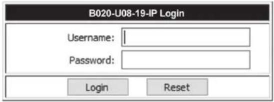
- Provide a valid Username and Password (set by the KVM switch's administrator), and click Login to bring up the OSD Main Page.
Note: If logging in for the first time, a "Change Password" prompt (shown) will appear requiring you to immediately change the password from the default.
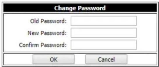
Please enter the old default password and then a new unique password in the remaining fields. It is strongly recommended that you also change the Username to a unique one as well (see section 5.7.4 Changing the Super Administrator Login for details).
Note: If you supply an invalid login, the authentication routine will return an Invalid Username or Password message. If you see this message, log in again being careful to enter the correct Username and Password.
6.5.2 AP Windows Client Login
In some cases, the Administrator may not want the B020-Series KVM Switches to be available via browser. The Windows AP Client allows Windows systems users access to the KVM switch without having to go through a browser.
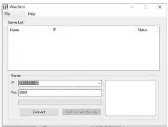
The AP Windows Client can be found in the Download Section of the OSD or on the CD that came with your B020-Series KVM Switch. If you do not have access to the CD, and browser access to the KVM switch has already been disabled, you will need to obtain the file from your system administrator. Once you have saved the AP Windows Client, go to its location and double-click the WinClient.exe icon to bring up the Windows Client Connection Screen.
Notes:
- If you have trouble opening the AP Windows Client, save it to your desktop and try again.
- If you supply an invalid login, the authentication routine will return an Invalid Username or Password message. If you see this message, log in again being careful to enter the correct Username and Password.
6. KVM Operation (continued)
The Connection Screen
A description of the contents of the Connection Screen is given in the following table:
| Item Description | |
| Menu Bar | The Menu Bar contains two menus; File and Help. The File Menu allows the operator to Create, Save, and Open Work files. |
| Server List | Each time the WinClient.exe file is run, it searches the User's LAN segment for B020-Series KVM Switches, and lists the ones it finds in this box. Double-click on any of the units in this list to connect to it.Note: For a switch to show up in the Server List, the Enable Device List check box in the Operating Mode page (see Operating Mode section under Device Management in OSD Operation for details) must be checked and the Program service port in the Network page (see Network section under Device Management in OSD Operation for details) must be set to the same number as in the AP Windows Client Port field. |
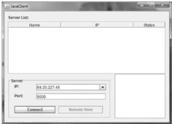
| Server This area is used when you want to connect to a B020-Series KVM Switch at a remote location.Click on the IP drop-down and select an address from the list. If the address you want is not listed, key in the target IP address in the IP field, and its port number in the Port field.When the IP address and port number have been specified, click Connect to bring up a login dialog box. Provide a Username and Password as provided by your system administrator and click OK to establish a connection with the B020-Series KVM Switch.When you have finished with your session, click Disconnect to end the connection. | |
| Message List Lists status messages regarding the connection to the B020-Series KVM Switch. | |
| Switch to Remote View | Once a remote connection with a B020-Series KVM Switch has been established, this button becomes active. Click it to switch to the KVM Switch's Main OSD Page. |
The File Menu
The File Menu allows the operator to Create, Save, and Open Work Files. A Work File consists of all the information specified in a Client session. This includes the items in the Server List and Server IP List.
Whenever a user runs the Client program, it opens with the values contained in the current Work File, i.e. the values that were in effect when the program was last closed.
The File menu consists of three items:
| Item Description | |
| New Allows the user to create a named work file so that its values will not be lost and will be available for future use | |
| Open Allows the user to open a previously saved work file and use the values contained in it | |
| Save Allows the user to save the values presently in effect as the current work file | |
| Exit Exits the AP Windows Client |
6.5.3 AP Java Client Login
In those cases in which the Administrator does not want the B020-Series KVM Switch to be available via browser and the remote user is not running Windows, the AP Java Client provides access to the KVM switch.
After downloading the AP Java Client, go to the location on your hard disk where you downloaded the program and double-click on it to bring up the connection screen. The AP Java Client connection screen is the same as the Windows version, except that it does not contain a menu bar with File and Help menus.
6. KVM Operation (continued)
- If your KVM is displayed in the Server List, connect to it by highlighting it and clicking on the Connect button.
Note: For a switch to show up in the Server List, the Enable Device List checkbox in the Operating Mode page (see 7.2.13 Operating Mode for details) must be checked and the Program server port must match what is set in the Network page (see 7.2.14 Network for details) - If your KVM does not display in the Server List, enter in its IP address in the IP server field and click the Connect button.
- Upon clicking the connect button, you will be prompted to enter your username and password. Enter in your username and password and press OK.
- When connected, the Remote View button will be activated. Click on it to access the KVM remotely. Click on the Disconnect button to log out of the KVM switch.
6.6 Remote Session Operation
After you have successfully logged in (see Logging Into the B020-Series KVM Switch section), the B020-Series KVM Switch OSD Main Page appears with the Port Access tab selected:
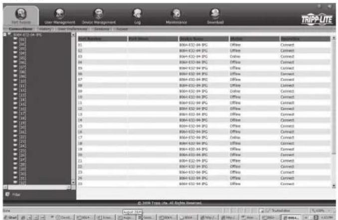
Note: The AP Client and Local Console versions feature a Control Panel in the top center of the screen that appears when scrolled over with the mouse. The web browser version's Control Panel is only available when a port has been accessed. (See Control Panel section for details.)
All the ports that a user is permitted to access are listed in the Port Selection panel at the left of the page. Ports to which users do not have access will not be displayed in their OSD. Double-click a port icon to access the device attached to it. Once you switch to a port, its screen displays on your monitor. Depending on whether you have Full Access or View Only access to the port, you may or may not be able to operate the remote computer using your keyboard and mouse.
![[02] Windows XP My Documents My Computer My Network Stores Recycle Web Internet Explorer Shortcase Windows Media Save](/content/2026/04/591621/images/0b5b0f8daa0daf7046cfcdd9ae7ff64a5f99f028ec847266b86bd162f4878c35.jpg)
6.6.1 Control Panel
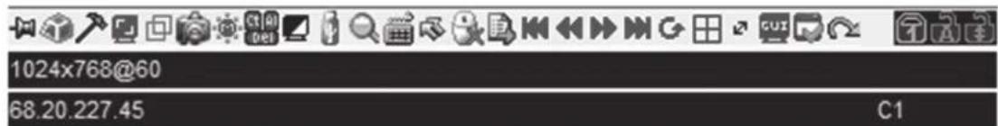
The Control Panel is provided as a way for the user to optimize and control the remote session. Regardless of whether you initiated a remote session via the Windows or Java browser and non-browser clients, the control panel and its functionality remain the same. To display the Control Panel, hover your mouse pointer over the top-center of the remote screen.
The Control Panel consists of an icon bar at the top and two text bars at the bottom. When the mouse pointer is hovered over an icon, the description of the icon is displayed in the text bar. When the mouse pointer is not over an icon, the text bars display the video resolution of the selected computer and the IP address of the KVM switch. You can drag the control panel to any location on the remote screen by hovering over the text bar, and then clicking-and-dragging it. Each of the icons contained in the Control Panel and their functionality is explained in the sections that follow.

Always on Top / Auto Hide – Click this button to toggle between displaying the control panel all the time, or to allow it to disappear after a few seconds of inactivity.

Hotkeys / Macros – The Hotkeys / Macros page allows the user to use Hotkeys and Macros to manipulate the remote computers. The user can enable/disable hotkeys, and create/edit User Macros. The sections that follow describe how these features work.
6. KVM Operation (continued)
Hotkeys
Various configuration actions related to the keyboard, video and mouse can be performed via hotkey combinations. The Hotkey setup utility is accessed by clicking on the Hotkey / Macros icon and then clicking on the Hotkeys button at the top of the screen. The Hotkeys screen displays the available hotkeys and their corresponding hotkey combinations.
By default, the only hotkeys that are enabled are the Exit Remote Location and Substitute Alt Key hotkeys. To enable/disable a hotkey, simply check/uncheck the box to the left of it. To change a hotkeys command sequence, follow the steps below.
- Highlight the desired hotkey and click on the Set Hotkey button.
- Key in the desired hotkey combination, one key at a time. The keys will be displayed in the hotkey column as they are entered.
Note: Clicking the Cancel button will cancel the recording process. Clicking on the Clear button will delete any keys that you entered while keeping the recording process active.
- When finished entering the hotkey sequence, click on the Save button.
Note: Clicking the Reset button will restore all of the default hotkey command sequences, and enable/disable defaults. You can use the same function keys for more than one hotkey command sequence, as long as the first key is not the same. For example, you can use [F1, F2, F3] for one action and [F2, F1, F3] for another, but you cannot use [F1, F3, F2] once [F1, F2, F3] has been used.
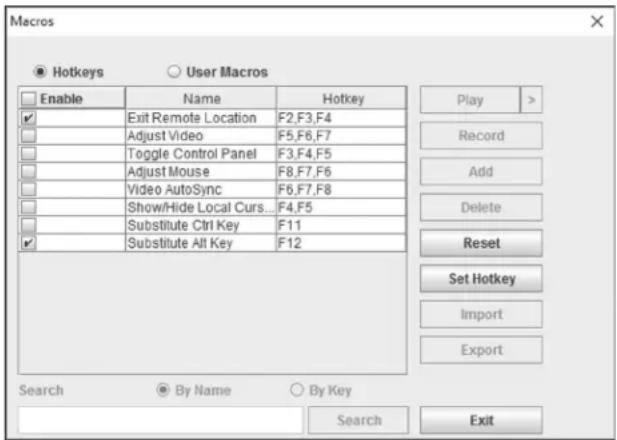
The table below lists the default hotkeys, along with a description of their functions and their default command sequences.
Hotkey Description Command Sequence
| Exit Remote Location Closes you out of a remote session. [F2, F3, F4] | ||
| Adjust Video Opens the Video Settings screen. [F5, F6, F7] | ||
| Toggle Control Panel | Toggles the Control Panel off and on. When off, you will not be able to access the control panel. | [F3, F4, F5] |
| Adjust Mouse | When the local and remote mouse pointers go out of sync, this command brings them back together again. | [F8, F7, F6] |
| Video Auto-Sync Performs a video auto-sync. [F6, F7, F8] | ||
| Show/Hide Local Cursor Toggles the local mouse pointer on/off. [F4, F5] | ||
| Substitute Ctrl Key | By default, hotkey combinations that use the Ctrl key, such as [Ctrl, Alt, Delete], get sent to the local computer. This hotkey allows you to set a substitute Ctrl key that can be used for the remote computer. | F11 |
| Substitute Alt Key | By default, hotkey combinations that use the Alt key, such as [Ctrl, Alt, Delete], get sent to the local computer. This hotkey allows you to set a substitute Alt key that can be used for the remote computer. | F12 |
6. KVM Operation (continued)
User Macros
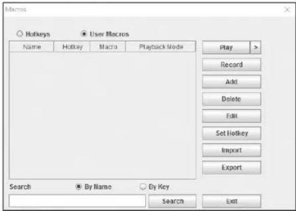
The User Macros page allows you to add macros to the KVM switch that can be performed on any of the connected computers using the Macro List feature of the control panel. (See Macro List section under Control Panel in Remote Session Operation for details.) By default, the User Macros page is displayed when the Hotkeys / Macros icon is clicked on. To display the page when it isn't selected, click on the User Macros button at the top of the Hotkeys / Macros screen.
To create a macro, follow the steps below.
- Click the Add button on the right side of the screen.
- In the name field that appears, key in a name for the macro you are adding.
- With the new macro highlighted, click the Record button on the right side of the screen. Recording will begin and the following panel will be displayed in the upper-left corner of the remote screen.

- Enter in the macro hotkey sequence and then click the Done button. You will be returned to the User Macros screen, with your macro name and hotkey combination added to the list. Repeat this procedure for any additional macros you wish to create.
Note: Clicking the Pause button will pause/unpause the recording of the hotkey sequence. Clicking the Cancel button will cancel the recording of the hotkey sequence. Clicking the Show button will display the hotkeys as they are entered.

Video Settings – The Video Settings screen allows you to adjust the placement and picture quality of the remote screen. The quality of the image display has a direct effect on the keyboard and mouse response time. Higher quality video results in more information being transferred over the network, which can cause slow keyboard and mouse response time in slower networks. Click this icon to open the Video Settings screen.
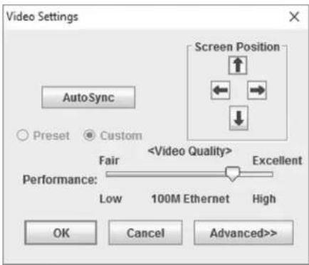
The table below describes the contents of the Video Settings screen:
| Setting Description | |
| Screen Position | Adjust the horizontal and vertical position of the screen using the Screen Position arrows. |
| Auto Sync Click this button to automatically detect the vertical and horizontal position settings of the remote screen. If the local and remote mouse pointers are not synced, performing this function will normally bring them back into alignment. If Auto Sync fails to align the screen properly, use the Screen Position arrows to make manual adjustments. | |
| RGB Move the RGB (Red, Green, Blue) slider bars to adjust the corresponding color component of the video image. Check the Set to Grayscale checkbox to display the video of the remote computer in black and white. If the remote keyboard and mouse response time is slow or choppy, checking the Set to Grayscale option can speed them up. | |
| Gamma This sect on allows you to adjust the video display's gamma level. This function is discussed in detail in the Gamma Adjustment section following this table. | |
| Performance Move the slide bar to adjust the video quality based on your network speed. Higher quality video results in more information being transferred over the network, which can cause slow keyboard and mouse response times. Adjust accordingly to your network speeds. | |
| Color Depth Control | This setting adjusts this amount of color information being sent over the network. To enable this setting, check the Enabled check box. A higher setting will provide more color, which may slow down keyboard and mouse response time. A lower setting may improve keyboard and mouse response times. |
| Video Quality Drag the slider bar to adjust the overall quality of the video of the remote computer. On slower networks, lowering the video quality can help improve keyboard and mouse response time. | |
| Enable Refresh The remote screen can be set to be redrawn every 1 to 99 seconds, eliminating unwanted artifacts that would otherwise remain on the screen. Click the Enable Refresh checkbox to activate this feature, and then enter in the desired refresh rate. | |
| Transparency Adjusts the transparency of the toolbars displayed by the Windows and Java clients. Move the slider bar until the transparency is set to the desired level. | |
| Detect Tolerance | This setting governs allowable pixel changes. A high setting limits changes, resulting in lower video quality and less data transfer. A low setting allows more changes, resulting in higher video quality and more data transfer. On slower networks, a high detect tolerance setting can help improve keyboard and mouse response time. |
6. KVM Operation (continued)
Gamma Adjustment
If it is necessary to correct the gamma level for the remote computer, use the Gamma function in the Video Settings screen. Under the Basic configuration, the gamma drop-down list includes ten preset and four user defined gamma levels to choose from. Simply select the desired setting from the drop-down list. To set your own gamma levels, follow the instructions below.
- Click the Advanced button to bring up the gamma adjustment settings.
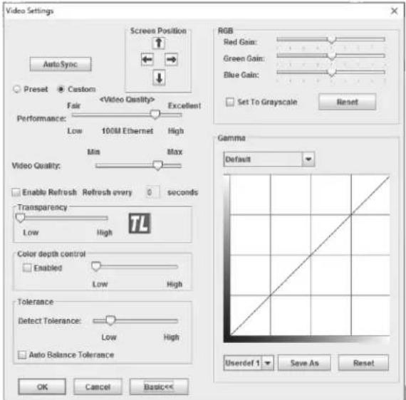
- Click and drag the diagonal line at as many points as you wish to achieve the display output you desire. Click the Reset button at any time to abandon changes and return to the default gamma settings. Click the Cancel button to abandon changes and close the Video Settings screen.
- To save the new gamma settings, select a user defined setting from the drop-down list and click the Save button. Your gamma settings will be saved to the selected user defined option.

Video Auto Sync – Click this icon to have the vertical and horizontal offset values of the remote screen automatically detected and synchronized with the local screen.
Note: If the local and remote mouse pointers are out of sync, performing a video auto sync will normally bring them back into alignment. If the video auto sync fails to align the screen properly, use the screen position arrows in the Video Settings screen to make manual adjustments.

Screen Mode – Click this icon to toggle Full Screen mode on/off. For those accessing the KVM via one of the Windows clients, right-clicking this icon will toggle Keep Screen Size on/off. When Keep Screen Size is enabled, turning on Full Screen mode will not change the size of the remote screen. For example, remote screens that are set to resolutions lower than that of the local monitor will be displayed as a box inside of the local display. When both Keep Screen Size and Full Screen Mode are enabled, the remote screen will be displayed as a box with a black background. If Keep Screen Size is disabled and Full Screen Mode is enabled, the screen will be stretched to fit the entire local monitor.
Note: Keep Screen Size can only be toggled on/off when using one of the Windows clients. When using one of the Java clients, Keep Screen Size is always enabled.

Snapshot – Clicking this icon will take a screenshot of the remote computer and save it to the local computer. By default, snapshots are saved to the local computer's desktop. The file type, quality and location can be changed via the Customize Control Panel page.

Message Board – The B020-Series KVM supports multiple user logins, which can give rise to access conflicts. To alleviate this problem, a message board feature has been provided that allows users to communicate with each other.
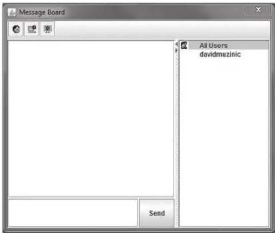
The buttons on the button bar at the top of the message board are toggles. The actions for each of these buttons are described in the table below.
Button Function
Enable/Disable Chat – When disabled, this icon displays next to the disabled user's name in the User List panel of all users' message boards. Messages directed to the disabled user are not displayed on the message board. The button is shadowed when chat is disabled.
Occupy/Release Keyboard/Video/Mouse – When you occupy the KVM, other users cannot see the video, and cannot input keyboard or mouse data. A prompt will come up on the locked out users' monitor stating which user has occupied the KVM. The button in the message board is shadowed and this icon displays next to the occupying user's name in the User List of all users' message boards.
Occupy/Release Keyboard/Mouse – When you occupy the KVM, other users can see the video, but cannot input keyboard or mouse data. The button is shadowed and this icon displays next to the occupying user's name in the User List of all users' message boards.
User List Panel
- To hide/unhide the User List panel, click on the arrows in the panel separator.
- The names of all the logged in users appear in the User List panel. Select the names of the users that you wish to communicate with before sending your message.
- If a user has disabled chat, its icon displays before that user's name.
- If a user has occupied the KVM or the KM, the corresponding icon displays before that user's name.
6. KVM Operation (continued)
Compose Panel
Type your message into this panel and then click the Send button or press the [Enter] key to post the message to the message board.
Note: You must select the user that you want to communicate with from the user list. To send a message to all users, simply click All Users in the user list.
Message Display Panel
Messages that users post to the board, as well as system messages, display in this panel. If you disable chat, messages that get posted do not appear.

Ctrl - Alt - Delete - Click this icon to send the [Ctrl, Alt, Delete] command to the remote computer.

Set to Grayscale – Click this icon to display the remote video in black and white. On slower networks, displaying the remote video in black and white can help improve keyboard and mouse response time.

Zoom – Click this icon to zoom in on the remote display. You can choose to display the screen at 100%, 75%, 50% or 25%. Checking the 1:1 checkbox will keep the screen contents sized in a 1:1 ratio, regardless of whether you choose to display the remote session at 100%, 75%, 50% or 25%.

On-Screen Keyboard – The B020-Series KVM switch features an on-screen keyboard, available in multiple languages, with all of the standard keyboard keys for each language. Click this icon to display the on-screen keyboard.
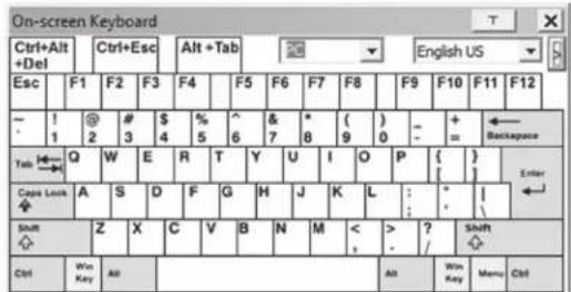
- To switch to a different language keyboard, open the drop-down list in the upper-right of the on-screen keyboard and select the desired language.
- To expand the keyboard to include the number pad, click on the arrow icon to the right of the language drop-down menu.
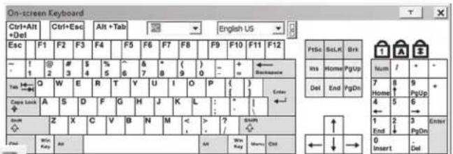

Mouse Pointer – Click to choose how the local and remote mouse pointers are displayed. You can choose to display Dual mouse pointers, Crosshairs mouse pointers, the local mouse pointer as a tiny dot (not available via Java), or only the remote mouse pointer. Dual mouse pointers display both local and remote mice as arrows. Crosshairs mouse pointers display the local mouse as a cross, and the remote mouse pointer as an arrow. When displaying the local mouse pointer as a tiny dot, the remote mouse pointer will be displayed as an arrow.

Mouse Sync Mode - Click to toggle between automatic and manual mouse sync modes. When set to automatic, a green checkmark appears on the icon. When set to manual, a red x appears on the icon.
Note: This icon is only active on computers that are connected to the KVM using a USB SIU. The auto sync functionality only supports Windows and Mac (G4 and higher), and the adapter attribute OS setting must be set to Windows or Mac. (See Port Property section under Port Configuration in OSD Operation for details on the adapter attribute OS setting.)
Mac and Linux Considerations
A second Mac auto sync setting is available for Mac OS X 10.4.11 and higher. If you find that enabling automatic mouse sync per the instructions above does not provide satisfactory results, right-click the mouse in the black text area of the control panel, highlight the Mouse Sync Mode option and select Automatic for MAC 2.
Although Linux does not support automatic mouse sync mode, there is an additional setting in the Mouse Sync Mode drop-down menu for Redhat AS3.0 systems. If you are having difficulty synchronizing the local and remote mice, try right-clicking the mouse in the black text area of the control panel, highlight the Mouse Sync Mode option and select Automatic for Redhat AS3.0.
Manual Mouse Synchronization
If the local mouse pointer goes out of sync with the remote system's mouse pointer, there are a number of methods to bring them back into sync.
Before trying any mouse synchronization procedures, it is always a good idea to ensure that you go to your Mouse Properties Settings and set them according to the instructions that follow. The Mouse Properties Settings should be set on the computers attached to the B020-Series KVM Switch, not the computer you are using to access it.
Note: In order for the local and remote mice to synchronize, you must use the generic mouse driver supplied with the MS operating system. If you have a third party driver installed - such as one supplied by the mouse manufacturer - you must remove it.
Windows 2000:
- Open the Mouse Properties dialog box
- Click the Motion tab
- Set the mouse speed to the middle position (6 units in from the left)
- Set the mouse acceleration to None
Windows XP and later:
- Open the Mouse Properties dialog box
- Click the Pointer Options tab
- Set the mouse speed to the middle position (6 units in from the left)
- Disable Enhance Pointer Precision
Sun / Linux:
Open a terminal session and issue the following command:
Sun: xset m 1
Linux: xset m 0
6. KVM Operation (continued)
Mouse Synchronization Procedures
If you are having syncing problems after adjusting the mouse properties, try the following methods to help synchronize the local and remote mouse pointers.
Note: Mouse synchronization may require several seconds to take effect. Wait for 15 to 30 seconds to ensure that the mouse has had enough time to sync.
- When in a remote session, move the mouse pointer to the upper-center of the screen to open the control panel, and then move it back into the remote screen. The mouse pointers should align.
- Click the Video Auto Sync icon in the control panel. In most cases, the local and remote mouse pointers will sync following the video auto sync.
- Invoke the Adjust Mouse hotkey command (see Hotkeys section under Control Panel for details). This hotkey command defaults at F8, F7, F6.
- Adjust the video settings to decrease the amount of information being transferred over the network. The less data that is being sent, the faster the response time. In particular, the Quality and Detect Tolerance settings in the Video Settings screen (see Video Settings section under Control Panel for details) can help improve keyboard and mouse response time.
- Go to the Network page in the OSD and reduce the Network Transfer Rate setting. (See Network section under Device Management in OSD Operation for details.)
- Go to the display settings section of the remote computer and lower the video resolution, refresh rate and color settings.
- If the remote computer has a graphic desktop background, change it to a solid color background.

Macro List – Click this icon to display a drop-down list of the User Macros (see User Macros section under Control Panel for details) that have been added to the KVM switch. Select a macro to run it on the selected computer.

First Port – Click this icon to skip to the first accessible port on the installation.

Previous Port – Click to skip to the first accessible port prior to the currently selected port.

Next Port – Click to skip to the first accessible port after the currently selected port.

Last Port – Click to skip to the last port on the installation.

Scan Ports – Click to initiate Auto Scan mode. (See Auto Scanning section for details.)

Array Mode – Click to initiate Panel Array mode. (See Panel Array Mode section under The OSD Toolbar for details.)

Cat5 Cable Length – As the length of Cat5 cable between the KVM and connected computer can affect video quality, this setting is designed to compensate for shorter or longer lengths. Click to toggle through the Cat5 cable length options; Short (less than 32 ft. / 10 m), Medium (between 32 ft. / 10 m and 82 ft. / 25 m) and Long (over 82 ft. / 25 m).

Open GUI – Click to open the OSD.

Customize Control Panel – Click this icon to bring up the Customize Control Panel screen, which allows you to choose which icons are displayed in the control panel, as well as edit some of its features.
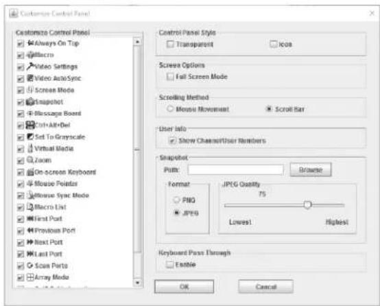
Customize Control Panel – The box on the left side of the screen displays a list of the available control panel features, with a checkbox next to each one. Check/uncheck a checkbox to display or remove the corresponding features icon from the control panel. By default, all features are included in the control panel.
Control Panel Style – This section allows you to determine how the control panel is displayed when it is dragged out of the default position in the top-center of the screen.
Note: There is a second default position for the control panel at the bottom-center of the screen.
- When the Transparent checkbox is checked, dragging the control panel away from one of the default locations will leave it displayed transparently in whatever location it was dragged to.
- When the Icon checkbox is checked, dragging the control panel away from one of the default locations will leave it displayed as an icon in whatever location it was dragged to.
- When both the Transparent and Icon checkboxes are checked, dragging the control panel away from one of the default locations will leave it displayed as a transparent icon in whatever location it was dragged to.
- When neither checkbox is checked, dragging the control panel away from one of the default locations will leave it displayed as normal in whatever location it was dragged to.
- If the control panel is located in either the top-center or bottom-center default locations, checking these checkboxes will have no effect.
Screen Options – This section allows you to make Full Screen Mode and Keep Screen Size the default settings when a remote session is activated.
Note: Keep Screen Size is not available when using the Java clients.
- Check the Full Screen Mode checkbox to display the remote screen in Full Screen Mode starting with the next time you login to a remote session.
- Check the Keep Screen Size checkbox to enable the Keep Screen Size feature starting with the next time you login to a remote session.
6. KVM Operation (continued)
Bus Info – The KVM Switch allows multiple users to access the connected computers simultaneously, with each user accessing one bus. In addition, multiple users can log onto the same bus at the same time, and share a remote session. The amount of buses is the same as the total number of simultaneous users. For example, a B020-U16-IP allows 2 users (1 remote, 1 local) to simultaneously access connected computers, therefore has 2 buses. When 2 users are logged on at the same time, each would be accessing the KVM on a separate bus. When a third user logs on, they are logged on to the first bus, which they are sharing with the first logged on user.
When the Bus Info checkbox in the Customize Control Panel screen is checked, the bus (channel) being accessed and the number of users on that bus (channel) is displayed in the control panel text bar. For example, C1/2 would signify that you are accessing the connected computers on bus (channel) 1, and there are 2 users currently accessing bus (channel) 1 at the same time.
Snapshot – The Snapshot section allows you to determine where snapshots are sent to, what file type they are saved as; and, if saved as a JPEG, the quality of the JPEG image. Although the Snapshot section is available to both Windows and Java users, the two differ in the types of files that can be saved. The Windows clients allow you to choose between a BMP and a JPEG file, whereas the Java clients allow you to choose between PNG and JPEG.
- Path – To select a location for snapshots to be saved in, click on the Browse button next to the Path field. Navigate to the desired location and select it.
- Format – Check the button of the file type that you want the snapshot to be saved in.
- JPEG Quality – If you select to save snapshots as JPEGs, you can adjust the quality of the JPEG image here. The higher the quality of the image, the larger the file size.
Keyboard Pass Through – When selected, the [Alt, Tab] function will be sent to the remote computer. When it is not selected, the [Alt, Tab] function is sent to the local computer. It is deactivated by default.

Exit - Click this icon to exit the remote session.

Lock LEDs – These icons display the status of the keyboard Num Lock, Caps Lock and Scroll Lock LEDs. You can click on them to toggle the corresponding lock function on/off. When first initiating a remote session, you may have to toggle these off/on to make sure they are synced up with your keyboard.
6.6.2 The OSD Toolbar
The OSD provides a toolbar to help you control the B020-Series KVM Switch from within the captured port. There are three hotkey combinations that can be used to pull up the OSD Toolbar and/or OSD when in a remote session:
- When in a remote session, hit the hotkey [Scroll Lock] twice to open the OSD Toolbar.
- When in a remote session, hit the hotkey [Scroll Lock] three times to open the OSD.
- When the OSD Toolbar is opened in a remote session, hit the hotkey [Scroll Lock] once to open the OSD.
The OSD Toolbar is shown below:
MHOHTX出
[01]
Depending on the settings that were selected for ID Display, the Port Number and/or the Port Name display at the right of the toolbar.
Note: When the toolbar displays, mouse input is confined to the toolbar area and keyboard input (other than the Scroll Lock/Control hotkey) has no effect.
The meanings of the toolbar icons are given in the table below:
Icon Description
| Click to skip to the first accessible port on the entire installation without having to invoke the OSD. | |
| Click to skip to the first accessible port previous to the current one without having to invoke the OSD. | |
| Click to begin Auto Scan Mode. The B020-Series KVM Switch automatically switches among the ports that were selected for Auto Scanning in the Port Select and Filter functions. This allows you to monitor their activity without having to switch among them manually. | |
| Click to skip from the current port to the next accessible one without having to invoke the OSD. | |
| Click to skip from the current port to the last accessible port on the installation without having to invoke the OSD. | |
| Click to bring up the OSD. | |
| Click to close the OSD toolbar. | |
| Click to invoke Panel Array Mode. (See Panel Array Mode section under The OSD Toolbar for details.) | |
| As the length of Cat5 cable between the KVM and connected computer can affect video quality, this setting is designed to compensate for shorter or longer lengths. Click to toggle through the Cat5 cable length options; Short (Less than 32 ft. / 10 m), Medium (Between 32 ft. / 10 m and 82 ft. / 25 m) and Long (Over 82 ft. / 25 m). |
6. KVM Operation (continued)
Toolbar Hotkeys
When the Toolbar is displayed, hotkeys can be used to switch between ports. The table below describes what actions can be performed.
| Hotkey Action | |
| ← | Skips from the current port to the first accessible port previous to it. To gain control of the selected port, hit the [Esc] key or click on the X icon in the Toolbar |
| → | Skips from the current port to the first accessible port after it. To gain control of the selected port, hit the [Esc] key or click on the X icon in the Toolbar |
| ↑ | Skips from the current port to the first accessible port on the installation. To gain control of the selected port, hit the [Esc] key or click on the X icon in the Toolbar |
| ↓ | Skips from the current port to the last accessible port on the installation. To gain control of the selected port, hit the [Esc] key or click on the X icon in the Toolbar |
| A | Starts an Auto Scan. To exit Auto Scan and take control of the currently selected port, hit the [Esc] or [Spacebar] key, or click on the X icon in the Toolbar. |
| P | Pauses an Auto Scan. To resume scanning, hit any key other than the [Esc] or [Spacebar] |
Panel Array Mode
Clicking the Panel Array icon on the OSD Toolbar or Control Panel invokes Panel Array Mode. Under this mode, the OSD divides your screen into a grid of panels:
- Each panel represents one B020-Series KVM Switch's ports, beginning with Port 1 at the upper left and continuing from left to right and top to bottom.
- When the Array is first invoked, it scans through each of the ports that were selected for Auto Scanning in the Port Select and Filter functions, and displays information about the port (port name, resolution, online status, port access status), at the bottom of the panel.
Note: The Panel Array scans at one-second intervals. The scan interval is not user definable.
- The number of panels in the array can be increased or decreased by clicking the Show More Ports or Show Fewer Ports icons on the panel array toolbar.
6.6.3 Auto Scanning
The Auto Scan function automatically switches among all accessible ports at regular intervals, so that the user can monitor their activity without having to manually switch between ports. The ports that are accessed in Auto Scan mode can be further filtered via the Filter section of the Port Access page. (See Filter section under Connections in OSD Operation for details.)
Setting the Scan Interval
The scan interval used during Auto Scan mode can be set in the User Settings menu. (See User Preferences section under OSD Operation for details.) The scan interval can be set from 1 to 255 seconds. The default is 5 seconds.
Invoking Auto Scan
Auto Scan Mode can be invoked when in the OSD or when in a remote session. When in the OSD, Auto Scan mode can be invoked by clicking on the Auto Scan button in the lower-left corner of the Port Access section. When in a remote session, Auto Scan Mode can be invoked by opening the OSD toolbar and tapping the A key. Once started, Auto Scan cycles through the ports in order, starting with the first accessible port on the installation. During Auto Scan Mode,
- If the computer connected to a port is on line, its screen displays in the panel. If not, the panel remains blank.
- Only ports that are accessible to the currently logged in user are displayed. For ports that are not accessible, the panel is blank.
- If you move the mouse pointer over a panel, information about the port displays at the bottom of the panel.
- You can access a computer/server connected to a port by moving the mouse pointer over its panel and double-clicking. This will switch you to the computer exactly as if you had selected it from the OSD Main screen.
Panel Array Toolbar
The Panel Array Toolbar provides shortcut navigation and control of the panel array. The icons in the Panel Array Toolbar are described below:
| Icon Description | |
 | Click this icon to keep thePanel Array Toolbarvisible at all times.Click it again to make the toolbar disappear after a few seconds. |
 | Click and drag any part of the toolbar that is not an icon to move the toolbar to another position on the screen. |
 | Pause panel scanning, leaving the focus on the currently selected panel. |
 | Click to move the focus of thePanel Array scan back four panels. |
 | Click to move the focus of thePanel Array scan to the previous panel. |
 | Click to move the focus of thePanel Array scan to the next panel. |
 | Click to move the focus of thePanel Array scan ahead four panels. |
 | Increase the number of panels in the array. |
 | Decrease the number of panels in the array. |
 | Toggle 4/3 aspect ratio. |
 | ExitPanel Array mode. |
an S appears in front of the Port ID Display to indicate that the port is being accessed under Auto Scan Mode.
Pausing Auto Scan
Auto Scan Mode can be paused in order to keep the focus on a particular computer by pressing P during an Auto Scan. When paused, the S that displays in front of the Port ID blinks On and Off. Pausing when you want to keep the focus on a particular computer can be more convenient than exiting Auto Scan Mode because when you resume scanning, you start from where you left off. If you were to exit and then restart Auto Scan Mode, the scanning would start over from the very first computer on the installation. To resume Auto Scan Mode after pausing, press any key except [Esc] or the [Spacebar], which will exit Auto Scan Mode completely.
Exiting Auto Scan
While Auto Scan Mode is in effect, ordinary keyboard functions are suspended. You must exit Auto Scan Mode in order to regain normal control of the keyboard. To exit Auto Scan Mode press [Esc] or the [Spacebar].
7. Administration
Administration of the KVM switch can be done through three different interfaces; Local Console OSD, Web Interface and Remote OSD. The Web Interface and Remote OSD give you the most administrative access to the KVM, whereas the settings in the Local OSD are more limited. The table details which settings are available in each interface, and whether those settings are accessible to Administrators, ordinary Users or both. The rest of this chapter goes into these interfaces and their settings in more detail.
| Local OSD Remote OSD Web Management InterfaceUser Admin User Admin User Admin | ||||||
| Set Language of OSD/GUI X X X X X X | ||||||
| Set Ports to Be Displayed in OSDs X X X X | ||||||
| OSD Hotkey X X X X | ||||||
| Port ID Display Mode X X X X | ||||||
| Port ID Display Duration X X X X | ||||||
| Scan Select X X X X | ||||||
| Scan Duration X X X X | ||||||
| Screen Blanker | X X X X | |||||
| Logout Timeout | X X X | |||||
| Beeper | X X X | |||||
| Edit Port Names | X X X | |||||
| Set Port Operating Systems | X | X | ||||
| Set Port Operating Systems | X | X | ||||
| Hotkey Command Mode (On/Off) | X X | |||||
| Hotkey | X X | |||||
| Port ID Display Position | X X | |||||
| Touchpad (On/Off) | X X | |||||
| Reset Station IDs | X | |||||
| Set Local Keyboard Language | X | |||||
| Set Local Console Mode | X | |||||
| Setup IP Address | X | X | X | |||
| View Firmware Version | X | X | X | |||
| Firmware Upgrade | X | X | X | |||
| Reset Default Values | X | X | X | |||
| Clear Port Names | X | X | X | |||
| View Device Name | X | X | ||||
| View MAC Address | X | X | ||||
| Add, Edit and Remove Administrators/Users | X | X | ||||
| Port Access - Full/View Only/No Access | X | X | ||||
| Setup DNS Server Address | X | X | ||||
| IP Installer Settings - Enabled/View Only/Disabled | X | |||||
| Enable and Setup RADIUS and LDAP Servers | X | X | ||||
| Log Server Settings - MAC Address and Port Settings | X | X | ||||
| Enable and Setup IP Address Filters | X | X | ||||
| Enable and Setup MAC Address Filters | X | X | ||||
| Set a Default Web Page Name | X | X | ||||
| Login Failure Settings | X | X | ||||
| Enable/Disable ICMP, Browser, Device List, Multiuser and Force All to Grayscale | X | X | ||||
| Mouse Sync Mode - Automatic/Manual | X | X | ||||
| Backup and Restore System Configuration and User Accounts | X | |||||
7. Administration (continued)
7.1 Local Console OSD
Upon logging into the Local Console OSD, the main page appears (see figure). Administrators have access to all features in the OSD, whereas Users have access to everything except the F4 Admin page and the F6 Broadcast (BRC) function. The Local Console OSD administrative settings are described in the following section.

7.1.1 Local Console OSD F2 LIST Function
This function lets you tailor the list of ports the OSD will display on the Main Screen. The submenu choices and their meanings are given in the table:
Note: The ports that are displayed in the OSD main screen are the only ports that will be affected under Broadcast Mode. (See page 14 for details on Broadcast Mode.)
| Setting Description | |
| ALL | Lists all of the ports on the installation that are accessible to the logged-on user, whether they are powered-ON or not. |
| POWERED ON Lists all of the | ports on the installation that are both accessible to the logged-on user and powered-ON. |
| QVIEW | Lists all of the ports on the installation that are set as Quick View ports by an administrator. (See page 28 for details on Quick View ports.) |
| QVIEW + POWERED ON | Lists all of the ports on the installation that are both set as Quick View ports by an administrator and are powered ON. |
7.1.2 Local Console OSD F3 Settings (SET) Page
This function allows each User and Administrator to set up their working environment. A separate profile for each is stored by the OSD and is activated according to the username and password provided during login. To change a setting:
1) Double-click on it, or highlight it and press the [Enter] key.
2) After you select an item, a submenu with more choices will appear. To make a selection, double-click on a choice or highlight it and press the [Enter] key.
7. Administration (continued)
The settings in the F3 SET page are explained in the following table:
| Setting Description | |
| OSD HOTKEY | Select the hotkey sequence that invokes the OSD (both Local Console OSD and Remote OSD); [Scroll Lock, Scroll Lock] or [Ctrl, Ctrl]. This is set to [Scroll Lock, Scroll Lock] by default. |
| PORT ID DISPLAY POSITION | This setting allows you to position the Port ID anywhere on the screen. The default is the upper left corner. When selected, the screen switches to the last selected port, and displays its Port ID. To position the Port ID, use the touchpad or the keyboard arrow keys, as well as the [Pg Up], [Pg Dn], [Home], [End], and [5] keys (on the numeric keypad with [Num Lock] off). When the Port ID is in the desired location, double-click or press the [Enter] key to lock it in position and return to the OSD.Note: The Port ID is set independently for each port on the installation. The position specified here only applies to the port that is currently active. |
| PORT ID DISPLAY DURATION | This selection gives you the option of displaying the Port ID for 3 seconds, or having the Port ID always off. The default is to display for 3 seconds. |
| PORT ID DISPLAY MODE | Select how the Port ID is displayed: Port Number only, Port Name only or both Port Number and Port Name. The default is to display both Port Number and Port Name. |
| SCAN DURATION | This setting determines the amount of time spent on each port when in Auto Scan Mode. Key in a value from 1 - 255 seconds, and then press the [Enter] key. The default is 5 seconds; a setting of 0 (zero) disables the Auto Scan function altogether. |
| SCAN/SKIP MODE | Select which ports will be accessed during Auto Scan Mode and Skip Mode.ALL: All ports that are accessible to the currently logged-on userPOWERED ON: All ports that are both accessible to the currently logged in user and powered-onQUICK VIEW: Ports that are set as Quick View ports (see page 28 for details on Quick View ports) by an administratorQUICK VIEW + POWERED ON: Ports that are both set as Quick View ports by an administrator and are powered on The default setting is ALL. |
| SCREEN BLANKER | If the console is left idle for the amount of time set with this function, the screen is blanked. Key in a value from 1 - 30 minutes, and then press the [Enter] key. A setting of 0 disables this function. The default is 0 (disabled). |
| HOTKEY COMMAND MODE | Enables / Disables the hotkey command function. Hotkey Command Mode is enabled by default. |
| HOTKEY | Toggle between the two Hotkey Mode invocation sequences. Options are [Num Lock, Minus] and [Ctrl, F12]. |
| OSD LANGUAGE | Determines which language the OSD menus are displayed in. Choices are English, Spanish, French, German and simplified Chinese. |
| TOUCHPAD Enables/Disables the touchpad. | |
7. Administration (continued)
7.1.3 Local Console OSD F4 Administration (ADM) Page
This Administrator-only page allows administrators to configure the settings of the KVM switch. To change a setting:
1) Double-click on it, or highlight it and press the [Enter] key.
2) After you select an item, a submenu with more choices will appear. To make a selection, double-click on a choice or highlight it and press the [Enter] key.
The settings in the F4 ADM page are explained in the following table:
| Setting Description | |
| SET IP ADDRESS | This page allows administrators to set the network settings for the KVM switchDHCP: The first field allows you to enable or disable DHCP. When enabled, the KVM is assigned an IP address by the DHCP server. This setting is enabled by default. To disable the DHCP setting and set up a fixed IP address, press the [Spacebar] key. Once the DHCP is disabled, you will be allowed to edit the remaining fields in the SET IP ADDRESS page. In the remaining fields, enter in the IP Address, Subnet Mask and Default Gateway you want to assign to the KVM switch. When these fields have been populated, press the [Esc] key to exit and pull up a prompt asking if you wish to save the settings you just entered. If you do not wish to save the settings, press the [N] key. If you do wish to save the settings, press the [Y] key. Upon pressing the [Y] key, the settings will be saved and the KVM will be reset.Note: Only an IPv4 address can be assigned using the Local Console OSD. To assign an IPv6 address, use the Web Management Interface or Remote OSD. This page only allows you to set a fixed IP address or enable IP address assignment via DHCP server. It does not allow you to set the HTTP, HTTPS and Program access ports, assign a DNS server address, or edit the IP Installer settings. To set ports and assign a DNS server address, you can use the Web Management Interface or Remote OSD. To edit the IP Installer settings, you must use the Web Management Interface. |
| SET LOGOUT TIMEOUT | If there is no input from the console for the amount of time set here, the user will be logged out, requiring them to enter their username and password to regain access to the KVM. This can be set from 0 to 180 minutes, with 0 disabling the function. Simply type in the desired time frame and hit the [Enter] key to save your change. This is disabled (0) by default. |
| EDIT PORT NAMES | This function allows administrators to give each port a unique name, making it easier to find the computer you want to access. To add/edit a port name, do the following:1. Select the port by double-clicking on it, or by highlighting it and hitting the [Enter] key.2. A name field will appear at the bottom of the screen. Add or edit the port name and hit the [Enter] key to save the change. To exit without saving the change, hit the [Esc] key.Port names can have a maximum of 12 characters, including any combination of letters and numbers (A-Z, 0-9), and the following characters: Asterisk [*], Parentheses [(), Plus [+], Minus [-], Colon [:], Comma [,], Question Mark [?], Period [,], Forward Slash [/] and Space. Port names are NOT case sensitive. They will always display as uppercase in the OSD. |
| RESTORE DEFAULT VALUES | This allows the Administrator to restore all OSD settings to their factory default values except for the network settings, port names and username/passwords. When this function is accessed, a prompt will appear asking if you wish to restore the default settings. If yes, type in a Y and hit the [Enter] key. If no, press the [Esc] key to go back to the previous menu. |
| CLEAR THE NAME LIST | This function allows the Administrator to clear all of the port names that have been entered. As with the RESTORE DEFAULT VALUES, you will be prompted upon accessing this function. If you wish to clear the name list, type in a Y and hit the [Enter] key. If not, press the [Esc] key to go back to the previous menu. |
| ACTIVATE BEEPER | Turns the beeper sound ON or OFF. Type in Y to turn the Beeper sound on, or N to turn it off. You do not need to hit the [Enter] key after typing in Y or N, the change will be made automatically. |
| SET QUICK VIEW PORTS | Administrators can use this function to mark ports as Quick View ports. This provides a way to customize which ports are displayed in the OSD main menu, and which are accessible in Auto Scan and Skip Modes. To set ports as Quick View ports, do the following:1. Highlight the desired port and hit the [Enter] key, or click on it using the touchpad.2. Press the [Spacebar] to toggle Quick View status ON/OFF. An icon will appear in the QV column next to the selected port when Quick View status is turned on.Once Quick View ports are set, the OSD main page can be set up to display only Quick View ports, or only Quick View ports that are powered ON. Administrators can also set it up so that only Quick View ports, or powered on Quick View ports, are accessible in Auto Scan or Skip Modes. |
| RESET STATION IDs | This function is used when you change the position of one of the KVM stations in a daisy-chain. When you change the position of the station, the OSD does not recognize the change, and will not automatically update the main menu to display the stations in correct order. When this function is used, the KVM will scan the entire installation and update the station numbers accordingly. The port names of the affected stations will be kept; however, you will need to manually update all other settings (SET ACCESSIBLE PORTS, SET QUICK VIEW PORTS, etc.). |
| SET OPERATING SYSTEM | This allows the Administrator to set the operating system for the port to match that of the connected computer. To set the operating system, do the following:1. Highlight the desired port or click on it using the touchpad.2. Press the [Spacebar] to toggle between four options; WIN, MAC, SUN and OTHER. Each port is set to WIN by default.3. You do not need to press the [Enter] key to save this setting. |
| FIRMWARE UPGRADE | Note: The KVM switch has two sets of firmware, one to control IP Access and another to control the KVM's Mainboard, Input/Output Ports and Keyboard. The IP Access firmware must be updated via the Web Management Interface or Remote OSD. The KVM Mainboard, Input/Output Ports and Keyboard firmware must be updated via the local console OSD.In order to upgrade the KVM Mainboard, Input/Output Ports and Keyboard firmware, Firmware Upgrade Mode must be invoked via this setting. (See page 29 for details on performing a firmware upgrade.)When you select this option, the firmware version numbers are displayed on the OSD screen, and a prompt will ask if you wish to continue with a firmware upgrade. If yes, type in Y. If no, type in N. |
7. Administration (continued)
| Setting Description | |
| KEYBOARD LANGUAGE | Sets the language for an external keyboard connected to the KVM's external keyboard port. To select a keyboard language, double-click on the desired language or highlight it and hit the [Enter] key. You can choose between US English, UK English, German, Swiss German, French, Hungarian, Italian, Japanese, Korean, Russian, Spanish, Swedish and Traditional Chinese. |
| SET CONSOLE MODE | This allows administrators to set which consoles are enabled for use. Press the spacebar to toggle between three choices:Mode 0 – Both consoles are enabled.Mode 1 – Only the built-in LCD console is enabled.Mode 2 – Only the external console is enabled.This setting defaults at Mode 0. (Both consoles are enabled.) |
7.1.4 Local Console Firmware Upgrade
The KVM switch has two sets of firmware, one to control IP Access and another to control the KVM's Mainboard, Input/Output Ports and Keyboard. The IP Access firmware must be updated via the Web Management Interface or Remote OSD. The KVM Mainboard, Input/Output Ports and Keyboard firmware must be updated via the local console OSD. To upgrade the KVM's Mainboard, Input/Output Ports and Keyboard firmware, follow the instructions below:
- From a computer that is not connected to your KVM switch, download the firmware upgrade file from tripplite.com/support.
Note: If firmware upgrades are not on tripplite.com/support, there are no upgrades available for your unit. - Using the included firmware upgrade cable, connect the RJ11 jack on the LCD panel of the console to a DB9 COM port on the computer you just downloaded the firmware upgrade file to.
Note: Daisy-chained KVM switches will automatically receive the upgrade via the daisy chain cables. - Shut down all the computers on the KVM installation. Leave all KVM switches powered-ON.
- Open the local console OSD and navigate to the F4 ADM page.
- Scroll down to the FIRMWARE UPGRADE option and press the [Enter] key. Press [Y] to invoke Firmware Upgrade Mode.
- From the computer you downloaded the firmware upgrade to, run the downloaded file either by double-clicking on it, or by opening a command line and entering the full path to it. The firmware upgrade utility welcome screen appears.
- Read and agree to the license agreement, and then click Next to continue. The firmware upgrade utility main screen appears, and the devices capable of being upgraded are listed in the Device List panel on the left side of the screen. There will be three firmware versions displayed for each device.
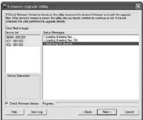
Note: If you receive a message that a device is not connected to the serial port, you may need to restart the computer the firmware upgrade utility is on.
- Highlight the Main firmware version of the desired device, and then click Next to begin the upgrade. If you checked the Check Firmware Version checkbox, the utility compares the device's firmware level with that of the upgrade files. If it finds that the device's version is higher than the upgrade version, it brings up a dialog box informing you of the situation and gives you the option to continue or cancel.
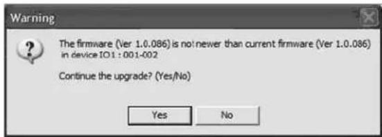
If you didn't check the Check Firmware Version checkbox, the utility installs the upgrade files without checking the version numbers. As the upgrade proceeds, status messages appear in the Status Messages panel, and the progress toward completion is shown on the Progress bar.
Note: Each of the three firmware files for the KVM will be upgraded in succession.
- After the upgrade has completed, a screen appears to inform you that the procedure was successful.
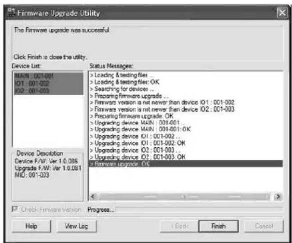
Click Finish to close the firmware upgrade utility.
Note: Upgrade the IP firmware via the Remote OSD or the Web Management Interface. (See page 40 for Remote OSD Firmware Upgrade or page 51 for Web Management Interface Firmware Upgrade.)
7. Administration (continued)
Firmware Upgrade Recovery
In the event of a firmware upgrade failure, or an aborted firmware upgrade, perform a firmware upgrade recovery by doing the following:
- Power OFF the switch. If it is part of a daisy-chain, disconnect it from the chain.
- Connect the firmware upgrade cable to the firmware upgrade port.
- Slide the Firmware Upgrade Recovery Switch to the Recover position.
- Power the switch back ON and repeat the upgrade procedure.
- After the switch has been successfully upgraded, power it OFF and then slide the Firmware Upgrade Recovery Switch back to the Normal position.
- If the switch is part of a daisy-chain, reconnect it to the daisy-chain.
- Power the switch back ON.
7.2 OSD Operation
When logging into the KVM switch via web browser, you are first taken to the Web Management Interface, with the Port Access page displayed. In addition to providing Windows Client and Java Applet applications used in accessing the connected computers, the Web Management Interface allows administrators to configure the KVM switch, view the log file and manage user accounts. This chapter discusses the different sections found in the interface and how you can use them to manage the KVM switch.
7.2.1 The OSD Main Page
After logging into the KVM switch, the OSD Main Page appears. Depending on how you logged into the switch, the interface will vary slightly. The following section describes the differences between these interfaces and the icons and functions you will find in them.
Web Browser Main Page
When logging into the KVM switch via web browser, the following page is displayed.
The following chart describes the components of this page.
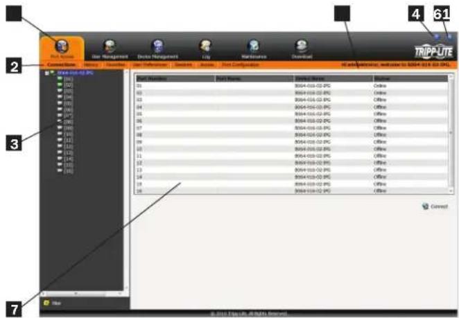
| No. Component Description | ||
| 1 | Tab Bar | The Tab Bar consists of category icons that take you to the various interfaces used to operate the KVM switch. The icons that are displayed in the Tab Bar depend on your user type (Super Administrator, Administrator, User), your permissions and the method you use to log into the KVM switch. |
| 2 | Menu Bar | The Menu Bar consists of sub-categories of the selected category icon. As with the Tab Bar, the sub-categories that show up in the Menu Bar depend on your user type and permissions. |
| 3 | Sidebar | The Sidebar displays a Tree Diagram that lists all of the functions available for the chosen category and sub-category. Clicking on one of the Sidebar functions will pull up the corresponding interface in the Interactive Display Panel. At the bottom of the Sidebar is a Filter button that allows you to display only the parts of the Tree Diagram that you filter for. (See Filter section under Connections in OSD Operation for details.) |
| 4 | About | Clicking on this icon pulls up the KVM switches firmware version |
| 5 | Logout | Clicking on this icon logs you out of the KVM switch |
| 6 | Welcome Message | When enabled (see User Preferences section under OSD Operation for details), this section of the main page will display a welcome message. This is disabled by default. |
| 7 | Interactive Display Panel | This is the main work area of the OSD. Different interfaces are displayed here depending on your category, sub-category and sidebar selections. |
7. Administration (continued)
AP Client Main Page
When logging into the KVM switch via the non-browser AP Windows or Java client, the following page is displayed.
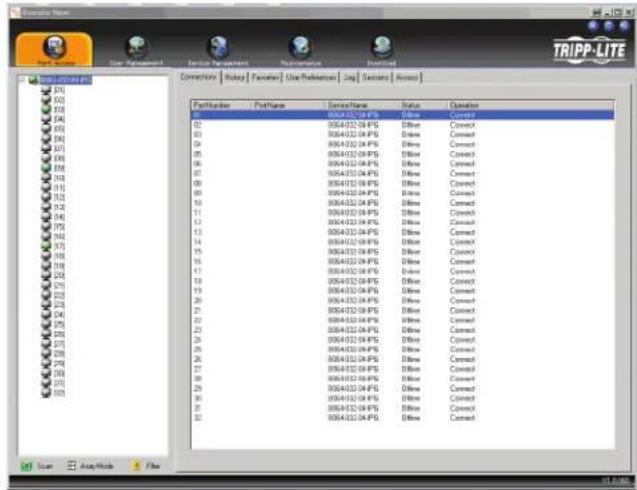
The AP Client Main Page differs from the Web Browser Main Page as follows:
- Instead of a Menu Bar, the AP Client Main Page has a set of notebook tabs that are used to select sub-categories. As with the Web Browser Main Page, the notebook tabs displayed depend on the user type and permissions.
- In addition to the Filter button at the bottom of the Sidebar, there is a Scan button and an Array Mode button.
- There is a hidden Control Panel (see Control Panel section under Remote Session Operation for details) at the upper center of the screen that becomes visible when you mouse over it.
- In addition to the two icons in the upper-right corner of the Web Browser Main Page, there is a third icon that closes the OSD and displays the screen of the last selected port.
The OSD can be navigated via keyboard using the commands in the table below:
| Command Description | |
| Ctrl + P Opens the Port Access category page | |
| Ctrl + U Opens the User Management category page | |
| Ctrl + C Opens the Device Management category page | |
| Ctrl + L Opens the Log category page | |
| Ctrl + M Opens the Maintenance category page | |
| Ctrl + D Opens the Download category page | |
| F1 Displays the KVM switches firmware version | |
| F2 Press to edit the name of the selected port | |
| F4 Selects the Sidebar panel | |
| F5 Selects the Interactive Display Panel | |
| F7 | Closes the OSD and displays the screen of the last select-ed port |
| F8 Logs you out of the KVM switch | |
7.2.2 OSD Tab Bar
The number and type of icons that appear on the tab bar at the top of the page are determined by user type (Super Administrator, Administrator or User) and the permissions assigned when the account was created. The functions associated with each of the icons are explained in the following table:
| Icon Description | |
| Port Access: This page is used to access and control the devices on the KVM switch installation. This page is available to all users. | |
| User Management: This page is used to create and manage Users and Groups, and to assign devices to them. This page is available to Super Administrator and Administrators, ordinary users will not have access to it. | |
| Device Management: This page is used by the Super Administrator to configure and control the overall operation of the KVM switch. This page is available to Super Administrators or Administrators/Users who have been given access. | |
| Log: This page displays the contents of the log file. (See Log section under OSD Operation for details.) | |
| Maintenance: This page is used to install new versions of the B020-Series KVM Switch firmware. This page is available to Super Administrators or Administrators/Users who have been given access. | |
| Download: Users with appropriate permission can click this icon to download the AP Windows Client, the AP Java Client and the Log Server. This page is available to all users, although what downloads a User can access is determined by the Super Administrator or Administrator. Note: The Download icon is not available via the local console. | |
There are three small icons in the upper right-hand corner of the page. Their functions are described in the following table:
| Icon Description | |
| Click this icon to close the OSD page and return to the display of the last selected port.Note: This icon is not available in the Web Browser Main Page. | |
| Click this icon to display the firmware version of the B020-Series KVM Switch. | |
| Click this icon to log out and end your B020-Series KVM Switch session. | |
7.2.3 Port Access
The Port Access section of the OSD is where users can access KVM ports, and control settings that directly affect that access. The sub-sections contained in the Port Access section are described in the pages that follow.
7. Administration (continued)
7.2.4 Connections
The OSD Main page is the same screen that you get when navigating to the Connections sub-section of the Port Access section. From this page you can connect to the KVM ports.
All switches and their ports, including cascaded KVM switches, are listed in a tree structure in the panel at the left of the screen:
![BRAU-02-01-07 [01]Text 1 [02]Windows\XP [03]Text 3 [04] [05] [06] [07] [08] [09] [10] [11] [12] [13] [14] [15] [16] [17] [18] [19] [20] [21] [22] [23] [24] [25] [26] [27] [28] [29] [30] [31] [32]](/content/2026/04/591621/images/bd9e51f38f75671d4281dd05f980eb796832b42c9ad9dda33641de6c596d71ee.jpg)
When accessing a port for the first time via web browser, users will experience a series of prompts:
Internet Explorer
When logging onto the KVM switch via Internet Explorer, the default viewer is the Windows ActiveX viewer. To use the Java Viewer when accessing the KVM switch via Internet Explorer, you need to update the Viewer setting in the User Preferences page (See User Preferences section under OSD Operation for details).
Note: Windows 7 users must run Internet Explorer as an administrator for the Active X control to work properly. If you don't run Internet Explore as an administrator, you will not be able to access the connected computers.
- When using the Windows ActiveX Viewer and clicking on a port for the first time, a screen will open up and you will be prompted to install the Windows ActiveX control. Click on the prompt and choose to install the ActiveX control.
Note: The screen that opens up may display a page that says the web pages certificate can not be trusted. If this is the case, click on the option to continue to the web page anyway.
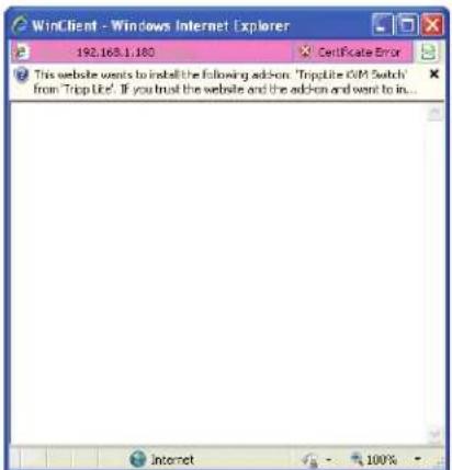
- When you install the ActiveX control, you may be prompted to resend the information in order to display the web page. Click Retry.
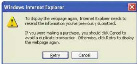
- Lastly, you will be prompted to install the software. Click Install.
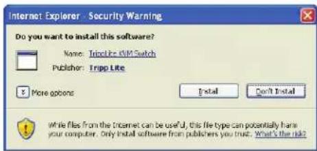
Non-Windows Browser
When using a non-Windows browser, you will automatically be connected to remote computers using the Java Viewer.
- When clicking on a port for the first time, you will be prompted to run the Java Viewer. Click ok. (To avoid this prompt every time you access a port, check the checkbox next to Do this automatically for files like this from now on.)
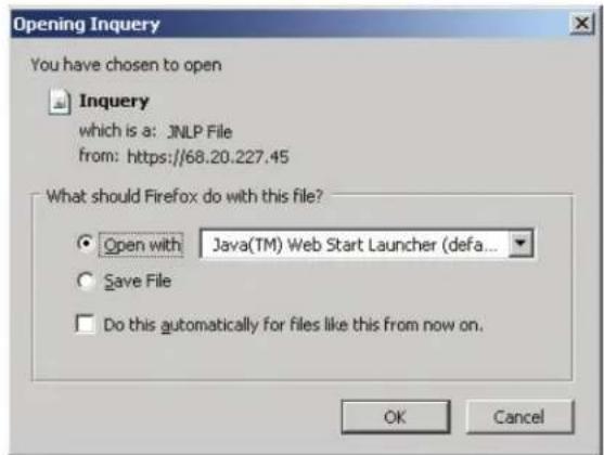
- You will then be prompted to run the Java Viewer, and trust the publisher (Tripp Lite). Click Run.
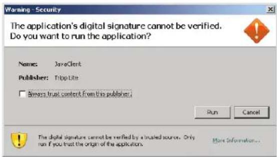
7. Administration (continued)
The Port Selection List
- Users only see the switches and ports they have been given access to.
- Ports are located under their parent switches. Click the Plus (+) in front of a switch to expand the tree and see the ports underneath it.
- When expanded, there is a Minus (-) before the KVM's device name. Click the Minus (-) to collapse the tree and hide the ports.
- A port's ID number is displayed in brackets next to the port icon. For convenience, you can give each port a unique name in addition to this ID.
- KVM switches and ports that are on line have their monitor screen icons lit green. The monitor screens are gray for devices and ports that are offline.
Port Configuration
When accessing the KVM via AP Windows or Java Client, right-click on any port in the Sidebar to configure a connected computer or switch. (This feature is not available when accessing the OSD via web browser.) A list with options pops up. Listed items vary depending on user type. Available configuration items are:
Expand
Copy
Item Access Type Description
| Expand/ Collapse Super Administrators, Administrators and Users | • If the device’s ports are not displayed, the dialog box entry is Expand.Click Expand to open the tree and display the ports.• If the device’s ports are displayed, the dialog box entry is Collapse. Click Collapse to close the tree view.Note: This item is only active for KVM switches that have child devices connected to them. This has the same effect as clicking the Plus (+) or Minus (-) in the tree view. |
| Copy Super Administrators, Administrators and Users | This item is only available for ports with computers/servers connected to them. It is used when creating a Favorites bookmark. (See Adding a Favorite section under Favorites in OSD Operation for details.) |
Port Naming
To assign, modify or delete a port name, follow the instructions below.
Note: Administrators and Users must be given configuration access to a KVM or computer port to be able to edit the port name. (See Device Assignment section under User Management in OSD Operation for details.)
- Click once on the port you want to edit to highlight it, wait one second and click on it again.
Note: This is not a double-click; it involves two separate clicks. Double-clicking will switch you to the device attached to the port.
After a second or two, the display changes to provide a text input box.
-
Key in a name for the port (or change/delete a previous one). The maximum number of characters allowed for a port name is 20. You can use any combination of letters, numbers, and symbols on the typewriter keys of keyboards with PC US English layout.
-
When you have finished editing the port name, press [Enter] or click anywhere outside of the input box to complete the operation.
Scan Scan
The Scan function automatically switches among all the ports accessible to the logged-on user at regular intervals, allowing their activity to be monitored automatically. (See Auto Scanning section under Remote Session Operation for details.)
Note: The Scan icon will not appear when accessing the KVM switch via web browser.
Array Mode Panel Array Mode
Panel Array Mode also permits port activity to be monitored automatically. The screen displays a grid of panels, each representing a port on the installation. Only ports that are online and user accessible are displayed. Offline or non-accessible ports are left blank. (See Panel Array Mode section under The OSD Toolbar in Remote Session Operation for details.)
7. Administration (continued)
Filter Filter
Filter allows you to control which ports are displayed in the Port Selection List, as well as which ports are scanned when Auto Scan Mode is invoked. When you click Filter, the bottom of the panel changes to look similar to the figure, below:
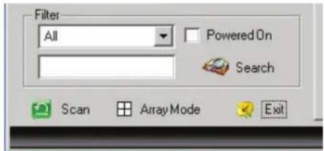
All – with no other filter options selected, lists all of the ports on the installation.
- Putting a check mark in the Powered On checkbox lists only the ports that have their attached devices powered on.
- The text input box and Search button allow you to key in a search string so that only port names that match what you key in show up in the list.
Interactive Display Panel
The Connections sub-section will display port status information on the Device Level and port connection and configuration options at the Port Level.
Device Level
When a KVM switch is selected in the Sidebar tree, the Connections sub-section will display a list of the ports that are accessible to the logged-on user.
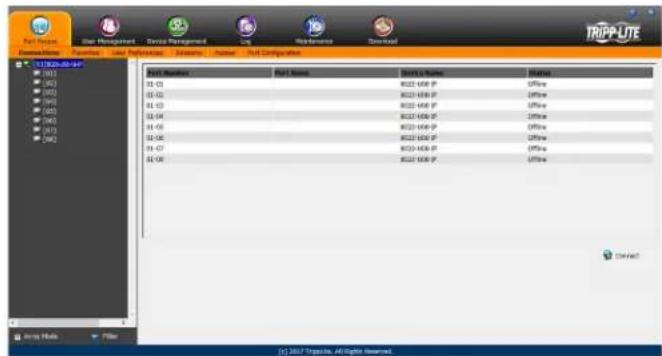
The chart below describes the attributes that are listed for each port.
| Attribute Description | |
| Port Number The KVM switch port that the computer or KVM is connected to | |
| Port Name If a port is assigned a name, it is displayed here | |
| Device Name The name of the KVM switch that the port is on | |
| Status Current status of the computer or KVM connected to the port; Online or Offline | |
| Connect | A Connect icon will be located underneath the port list. Highlight a port and click Connect to open up a remote session with the selected port displayed. |
Note: When accessing the KVM via web browser, this page can be sorted by any attribute by clicking on the column header.
Port Level
When a port is selected in the Sidebar tree, the Connections subsection will display port connection and configuration options.
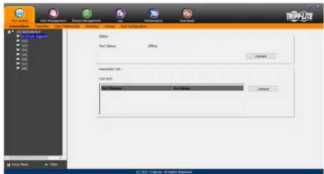
The chart below describes the sections that are displayed on this page.
| Section Description | |
| Status | This displays the Port Status; whether it is online or offline, and whether virtual media can be mounted to it. Click on the Connect button to open a remote session with the selected port displayed. |
| Associated Link | Each port can have additional ports associated with it, so that the user can access multiple ports via one connection page. Associated Links can be added/removed from the Port Configuration sub-section (see Port Configuration section under OSD Operation for details). When ports are available in the Associated Link section, simply highlight one and click the Connect button to open a remote session with that port displayed. |
7. Administration (continued)
7.2.5 Favorites
Favorites is similar to a bookmarks feature. Frequently visited ports can be listed on this page. Open this page and select the port instead of searching for it in the tree view. This feature is especially useful for larger, cascaded installations.
Note: Each Favorites bookmark that you create is a folder in which multiple ports can be saved.
Adding a Favorite
To add a port to Favorites, do the following:
- Right click in the main panel and click on the Add Favorite option that appears. An entry appears named Untitled Favorite.
- Click inside the text entry box to erase Untitled Favorite and key in the desired name.
![Port Active User Management Device Management Log Maintenance Download Connections Favorites User Preferences Messages Access Port Configuration TRIPP-LITE [1] 03200-450-SHP [2] With Support [3] [4] [5] [6] [7] [8] [9] [10] [11] [12] [13] [14] [15] [16] [17] [18] [19] [20] [21] [22] [23] [24] [25] [26] [27] [28] [29] [30] [31] [32] [33] [34] [35] [36] [37] [38] [39] [40] [41] [42] [43] [44] [45] [46] [47] [48] [49] [50] [51] [52] [53] [54] [55] [56] [57] [58] [59] [60] [61] [62] [63] [64] [65] [66] [67] [68] [69] [70] [71] [72] [73] [74] [75] [76] [77] [78] [79] [80] [81] [82] [83] [84] [85] [86] [87] [88] [89] [90] [91] [92] [93] [94] [95] [96] [97] [98] [99] Entry Mode Filter Add Modify Add to Remove G:\ 2017 Tripp In. All Rights Reserved.](/content/2026/04/591621/images/178a9d0686ece0a9e137f0174de1a045c9fcd0d2e24298927d631832dc6bd60c.jpg)
- To add a port, drag it from the Port Select list and drop it into the Favorites bookmark you just created. You can also add a port by right-clicking on it, and selecting Copy. After copying, right-click on the Favorites bookmark and select Paste. The KVM switch the port is connected to goes into the Favorites bookmark along with the port. The port is located under the switch, as it would be in the tree view on the left-hand panel.
Note: Right-clicking on a port that is already in a Favorites bookmark will give you the option to cut the port out of that bookmark and paste it into another Favorites bookmark.
- Repeat step 3 for any other ports you want to add to your Favorites bookmark.
Modifying a Favorite
To modify a Favorites bookmark, right-click on it and select one of the options from the pop-up menu that appears. The menu that appears allows you to perform the following options:
Collapse/Expand – As with the tree view on the right-hand side of the page, this option allows you to either collapse or expand the Favorites bookmark and all of its included ports
Add Favorite – Select this option to create a new Favorites bookmark Delete – Select this option to delete the selected Favorites bookmark Rename – Select this option to change the name of the Favorite bookmark
Copy – Select this option to copy all of the Favorites bookmark's contents, in order to paste them into another Favorites bookmark Paste – Select this option to paste copied ports into the selected Favorites bookmark
Note: Right-clicking on a port that is already in a Favorites bookmark will give you the option to Cut the port out of that bookmark and paste it into another Favorites bookmark.
7. Administration (continued)
7.2.6 User Preferences
The User Preferences page allows users to set up their own individual working environments. The B020-Series KVM Switch stores a separate record for each user profile, and sets up the working environment according to the Username that was used to access the KVM switch.
Note: The User Preferences page is different on the Web Browser version than the AP Client version. The AP Client version does not include the password, Viewer or Welcome Screen option.
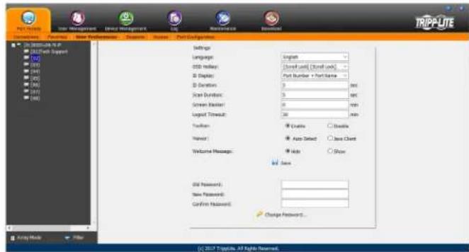
The page settings are explained in the following table:
| Setting Description | |
| Language | Selects the language that the interface displays in. Options are English (default), Spanish, French, German and simplified Chinese. |
| OSD Hotkey | Selects which hotkey controls the OSD function. You can choose from the following options; [Scroll Lock] [Scroll Lock], [Ctrl] [Ctrl]. The default is [Scroll Lock] [Scroll Lock]. |
| ID Display | Selects how the Port ID is displayed: the Port Number alone (PORT NUMBER); the Port Name alone (PORT NAME); or the Port Number plus the Port Name (PORT NUMBER + PORT NAME). The default is PORT NUMBER + PORT NAME. |
| ID Duration | Determines how long a Port ID displays on the monitor after a port change has taken place. You can choose an amount from 1—255 seconds. The default is 3 seconds. A setting of 0 (zero) means the Port ID is always on. |
| Scan Duration | Determines how long the focus dwells on each port as it cycles through the selected ports in Auto Scan Mode. Key in a value from 1—255 seconds. The default is 5 seconds; a setting of 0 disables the Scan function. |
| Screen Blanker | If there is no input from the console for the amount of time set with this function, the screen is blanked. Key in a value from 1—30 minutes. A setting of 0 disables this function. The default is 0 (disabled). When the screen is blanked, simply moving the mouse over the screen will bring it back up. Note: This setting affects the monitor of the local console only. |
| Logout Timeout | If there is no user input for the amount of time set with this function, the user is automatically logged out. A login is needed before the B020-Series KVM Switch can be accessed again. The default is 30 minutes. |
| Toolbar | The Toolbar option allows you to enable/disable the OSD Toolbar. (See The OSD Toolbar section under Remote Session Operation for details.) As all of the features of the OSD Toolbar are available in the Control Panel, you may want to disable it. The default setting is enabled. |
| Viewer | The Viewer option is available only when accessing the KVM switch via web browser. It allows you to choose what viewer is used to access a port. Auto Detect - The KVM switch will automatically choose which viewer to use based on the web browser being used. The Windows Viewer will be used for Internet Explorer and the Java Viewer will be used for all other browsers. Java Client - The KVM switch will always use the Java Viewer, regardless of what browser is being used. |
| Welcome Message | The Welcome Message option is also available only to those who access the KVM switch via web browser. This allows you to show or hide the welcome message that appears in the upper-right corner of the screen. |
| Save To apply any changes | that you make, you must click the Save button before exiting. |
| Changing a Password | To change a password, you must enter in the old password and the new password. The new password will need to be entered twice for security purposes. Once typed in, click the Save button to apply the change. |
7.2.7 Sessions
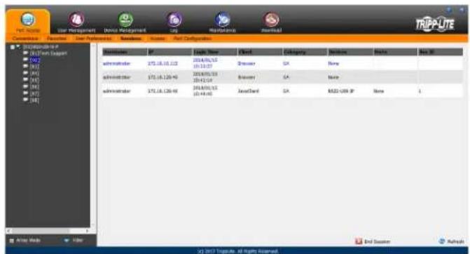
The Sessions sub-section allows Super Administrators and Administrators to see who is logged into the KVM switch, and provides information about each of their sessions. Super Administrators can see all accounts that are logged into the KVM, whereas Administrators are only able to see Administrator and User accounts.
It also provides the option of ending a session by selecting the account from the Sessions list and clicking the End Session icon. To refresh the Sessions list to display the most current information, click on the Refresh icon.
Note: The Sessions tab is only available for Super Administrators and Administrators. Users will not be able to access it.
7. Administration (continued)
7.2.8 Access
The Access sub-section allows Super Administrators and Administrators to set user access and configuration rights for switches and ports. As with the Sessions sub-section, Super Administrators can see all accounts, whereas Administrators can only see Administrator, User and Group accounts. The browser and non-browser Access sub-sections are the same, except the non-browser page includes drop-down filters above each column. These filters allow you to choose which accounts are displayed. For example, you can choose to display only those accounts that are given configuration access to the selected KVM/port by choosing the Permitted option from the drop-down menu above the configuration column.
Note: The Access sub-section is not available to User accounts, and will not show up when they log into the OSD.
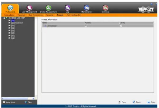
When the master KVM switch is highlighted in the port list, the Access sub-section displays only one setting column; Config. When a port is highlighted in the port list, the Access sub-section displays three settings columns; Access, Mount USB and Config. The section that follows describes these settings, and how to edit them.
Setting Description
| Access | The Access setting determines if an account is allowed to access the selected port, and if so, what level of access the account has. To edit this setting, click on the box in the Access column next to the account you wish to edit. Continue to click until you toggle to the desired setting.Full Access – This setting is represented by an icon that shows a pair of glasses and a pencil. It allows the corresponding account to both view video and perform operations on the selected port.View Only – This setting is represented by a pair of glasses only. It allows the corresponding account only to view video of the selected port.No Access – This setting is represented by an X, and denies the corresponding account access to the selected port. |
| Config | The Config setting determines if an account has permission to make changes to the master KVM or port configuration settings. To edit this setting, click on the box in the Config column next to the account you wish to edit. Click to toggle Config access on/off. A check mark enables access, an X disables access. Note: Config checkboxes are provided as a way for Super Administrators and Administrators to customize which ports Administrators and User accounts have Configuration access to. In order for the Config checkbox to enable Configuration access to a port, the Administrator or User account must be given Port Configuration access to the KVM switch. (See Permissions in the Adding User Accounts section under User Management in OSD Operation for details.) |
When you are done editing access rights to the selected port, click on the Save icon in the lower-right corner of the Access sub-section.
Also at the bottom of the page are Copy and Paste icons. These are used to copy the access settings from one port and paste those same settings to another port. To do this, simply highlight the port you want to copy and click on the Copy icon. Then highlight the port you want to paste to and click the Paste icon.
7. Administration (continued)
7.2.9 Port Configuration
The Port Configuration sub-section allows Super Administrators and Administrators to edit port properties settings, assign system macros to a port, and add/remove associated links. When the master KVM is highlighted and the Port Configuration sub-section is selected, the following screen appears.
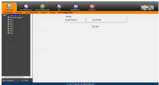
The only setting that appears on this page is the Occupy Timeout setting. This setting controls the amount of inactivity time before a port that is set to Occupy (see Port Property section on the following page for details) is opened for access by another user. Enter in a value from 0 to 255 seconds. The default is 3 seconds.
When a standard port is highlighted and the Port Configuration subsection is selected, a screen opens up that contains two sections; Port Property and Associated Link. The Port Property section is opened first by default.
Port Property
The Port Property page of this subsection lists status information about the selected port, and provides editable settings related to the connected computer and system macros. The contents of this page are described in the table below.
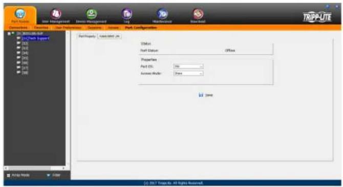
| Setting Description | |
| Status | Port Status – The status of the selected port is displayed here. If no computer/KVM is connected, or a computer/KVM is connected but not powered on, the port status will show up as Offline. If a computer is connected via B055-001-USB-V2 and powered on, the port status will show up as Online Mountable. If a computer is connected via any other SIU and powered on, the port status will show up as Online. |
| Properties | Port OS – Selects the OS of the computer connected to the port. The options are Win, Mac1, Sun and Mac2.Access Mode – Selects how the port is to be accessed when multiple users are logged onto the same port at the same time.Choices are Exclusive, Occupy and Share.Exclusive – The first user to access the port has exclusive control over it, and no other users can access the port. The Occupy Timeout function does not apply to ports that are set to Exclusive.Occupy – As with Exclusive, the first user to access the port has control over it; however, users that log on at the same time can view the ports video. If the user who controls the port is inactive for longer than the time set in the Occupy Timeout function, port control is transferred to the next user to access it.Share – In this mode, users simultaneously share control over the port. Input from the users is placed in a queue and executed chronologically. Under these circumstances, users can take advantage of the Message Board feature on the Control Panel (see Message Board section under Control Panel in Remote Session Operation for details). |
When you are done editing, click the Save icon to save the changes.
Associated Link
This page allows you to associate links to other ports in the installation with the highlighted port. When an associated link is made, it is displayed in the Associated Link table of the port's Connections screen (see Connections section under OSD Operation for details). To add an associated link, click the Add button, enter the desired port number in the box that appears, and click the OK button. It will then appear in the list of associated links. To remove a link, simple highlight it and click the Remove button.
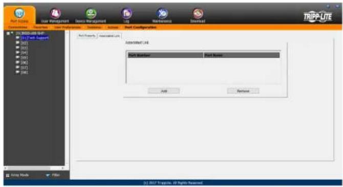
7. Administration (continued)
7.2.10 User Management
The User Management section allows Super Administrators, and Administrators and Users who have been given User Management permission, to add/edit accounts on the KVM switch. If an account has not been given User Management permission, the User Management icon will not show up in the OSD when they log in. The User Management section is displayed differently when accessing the OSD via web browser or one of the non-browser clients.
Note: Administrators with User Management permission can only add/edit Administrator and User accounts. Users with User Management permission can only add/edit User accounts. Super Administrators can add/edit all account types.
Adding User Accounts
There is a default Super Administrator account on the KVM switch that can be used to set up the KVM switch. The default Super Administrator username is administrator, and the default password is password. It is strongly recommended that you update this default accounts username and password to something unique. To add a new user account, do the following:
- Highlight Users from the list on the left side of the page, and then click the Add button at the bottom of the screen. The user information page opens.
- Enter in the appropriate information for the account you are creating, and click the Save button when you are done. The contents of the user information screen and their meanings are described in the table below.
- Upon clicking Save, a prompt appears to inform you that the operation succeeded. Click the OK button to exit.
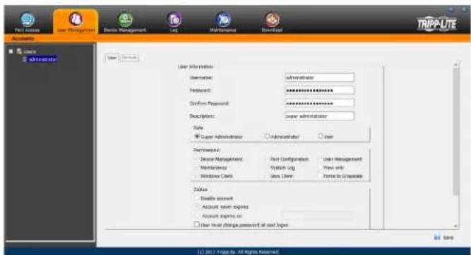
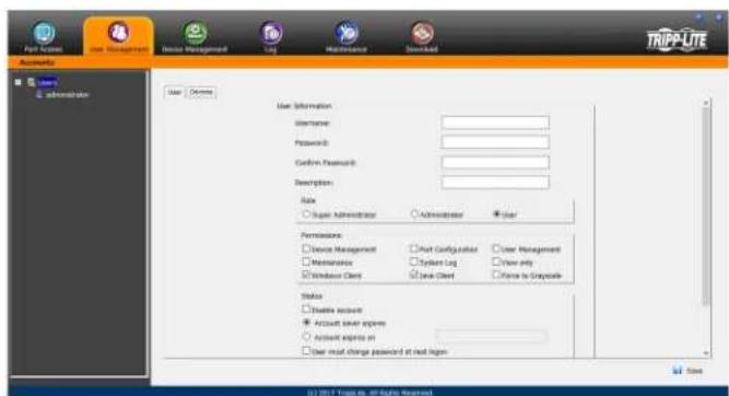
7. Administration (continued)
| Field Description | |
| Username | Enter a username for the account here. The username can contain up to 16 characters, and must meet the Account Policy requirements set in the Security sub-section. (See Security section under Device Management for details.) |
| Password | Enter a password for the account here. The password can contain up to 16 characters, and must meet the Account Policy requirements set in the Security sub-section. (See Security section under Device Management for details.) |
| Confirm Password | For security purposes you must re-enter the password. If the password does not match the password you just entered in the previous field, you will not be allowed to save the account information. |
| Description | Enter any additional information that you want to describe the account. This is an optional field. |
| Role | Select the type of account that you will be creating; Super Administrator, Administrator or User. There is no limitation on the number of each type of account that can be created, only a limit on the number of total accounts. You can create up to 64 accounts on the KVM switch.• Super Administrator – This account type has full access to all aspects of the KVM switch. They can fully access all computers/ devices connected to the KVM, change any and all settings, and add/edit any account type.• Administrator – This account type defaults at full access to the KVM switch, the same as a Super Administrator; however, which ports the account has Configuration access to is determined by a Super Administrator or Administrator that creates/edits the account.. Also, Administrators with User Management permission are limited to adding/editing Administrator and User accounts.• User – This account type defaults at no access to the KVM switch, and is only given the initial permissions of Windows Client, Java Client and SSH Client. Super Administrators and Administrators can customize a User profile however they like. If a User is given User Management permission, they are only allowed to add/edit other User accounts. |
| Permissions | The permission settings in this section of the user information page determine what functionality the account is able to use. Check the checkbox next to the permission to enable it for the account. Leave it unchecked to deny the account access to that functionality.• Device Management – Gives an account to access to the KVM settings found in the Device Management section, such as network and advanced network management (ANMS) settings. (See Device Management section under OSD Operation for details.) If this checkbox is not checked, the Device Management icon will not appear when the account logs into the OSD.• Port Configuration – Allows an account to edit the Port Configuration settings for individual KVM ports. (See Port Configuration section for details.) Note: The Port Configuration setting simply allows for an account to be given Configuration access to the connected ports. Configuration permission for each port must still be given via the Access sub-section of the Port Access section, or via the Devices tab in the Adding/Editing Users section.• User Management – Allows an account to add/edit other accounts. Administrators can add/edit Administrator and User accounts. Users can add/edit other User accounts. Super Administrators can add/edit all account types. If this checkbox is not checked, the User Management icon will not appear when the account logs into the OSD.• Maintenance – Gives the account access to the settings and functionality found in the Maintenance section, which includes upgrading the KVM and SIU firmware, and backing up and restoring the KVM settings, in addition to other features. (See Maintenance section for details.) If this checkbox is not checked, the Maintenance icon will not appear when the account logs into the OSD.• System Log – Gives the account access to the Log section of the OSD, where they can view events that have taken place on the installation and customize notification settings. (See Log section for details.) If this checkbox is not checked, the Log icon will not appear when the account logs into the OSD.• View Only – Limits the account to viewing the video of connected computers only. They will not be able to perform keyboard and mouse functions.• Windows Client – Gives the account access to the browser and non-browser versions of the Windows client.• Java Client – Gives the account access to the browser and non-browser versions of the Java client.• Force to Grayscale – Forces the account to view remote video in black and white. |
| Status | This section determines how long an account or password has until it expires or needs to be changed.• Disable Account – Disables an account, preventing it from accessing the KVM switch. This gives you an alternative to deleting the account, in which you can disable the account, and then reinstate it in the future without having to re-enter the account settings.• Account Never Expires – If this option is checked, the account will stay active forever, or until deactivated manually.• Account Expires On – To set a date for the account to be disabled on, check this checkbox and enter in a date in the corresponding field.• User Must Change Password at Next Logon – To force the account to change their password the next time they logon, check this checkbox. The next time the account logs on, they will be prompted to enter in a new password.• User Cannot Change Password – Check this checkbox to prevent the user from changing their password on their own.• Password Never Expires – If this option is checked, the account's password will stay active forever, or until manually forced to be changed.• Password Expires After – To force an account to change their password after a certain number of days, check this checkbox and enter in the number of days until the password expires. |
7. Administration (continued)
At this point you can do any of the following:
- Assign port access rights for a user by selecting the Devices tab.
- Add more users and/or create groups and finish configuring the user account later.
Modifying User Accounts
To modify a user account, do the following:
- Select the desired user's name from the User List or the Main Panel and click Modify.
- The same as when creating an account, make any necessary changes to the user account and click Save.
Deleting User Accounts
To delete a user account, do the following:
- Select the desired user's name from the Main Panel and click Delete.
- A confirmation dialog box will appear asking if you are sure you want to delete the selected user account. Click OK.
Device Assignment
When a user logs onto the KVM switch, the ports that they are allowed to access are displayed in the port list. Ports that they are not allowed to access are not displayed. Port access rights are assigned on a port-by-port basis in the user Device tab. To access the Device tab, you must pull up the user information page, and then click on the Device tab at the top-right of the page.
The Device tab page includes a list of the master KVM switch and its ports on the left, and three permission columns to the right of the list.
- Access – Determines if the account can access the port, and if so, whether they have View Only or Full access.
- Config – If the box is checked next to a port, the account is given access to edit the Port Configuration settings. (See Port Configuration section under OSD Operation for details.)
Note: For Configuration access to take effect, the account must also have been given Port Configuration permission. (See the Adding User Accounts section under User Management for details.)
To assign device permissions, do the following:
- Select the user name from the user list, or select the user name in the main panel. Click the Modify button.
- In the user notebook page that appears, click on the Device tab.
- Click on the Access or Config checkbox next to the desired port to toggle through the permission options. For the Access column, you can choose between full access, view only access or no access. For the Config column, you can choose between enabled or disabled. The permission types are exactly the same as those described in the Access sub-section. (See Access section for details.)
- When you have finished assigning permissions, click the Save button.
Note: You can simultaneously assign port access to multiple ports using the [Shift] or [Ctrl] keys. To highlight a group of consecutive ports, start by highlighting the first port, hold down the [Shift] key, and then highlight the last port that you wish to highlight. All ports from the first one you highlighted to the last will be highlighted. You can then click on any of the permission checkboxes to change that permission for all of the highlighted ports. To highlight multiple non-consecutive ports, start by highlighting the first port, hold down the [Ctrl] key, and then highlight each additional port one by one while continuing to hold down the [Ctrl] key. When all of the desired ports are highlighted, click on any checkbox to change that permission for all of the highlighted ports.
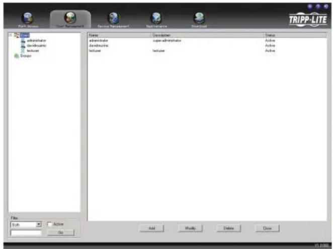
![Part Access User Management Device Management Log Maintenance Download TRIPP-LITE Accesses Users Administrator User Devices Name Accounts Check [0] BC35-1008-23-IP [10] [0] 202202022 [10] [04] [05] [06] [07] [08] Access X X X X X X X X X X X X X X X X X X X X X X X X X X X X X X X X X X X X X X X X X X X X Years ©) 2017 Topkite. All rights reserved.](/content/2026/04/591621/images/3f084fce633c6a389ec474928893f02acc72bae15199d00bc989fccfcf5e3c40.jpg)
7. Administration (continued)
7.2.11 Device Management
The Device Management section allows Super Administrators, and Administrators/Users who have been given permission, to configure and control the KVM switch. When the Device Management icon is selected, it opens with the Device Information page displayed.
Note: If you do not have permission to configure the KVM switch, the Device Management icon will not appear when you log onto the KVM.
7.2.12 Device Information
The Device Information page displays general information about the settings of the KVM switch, and allows you to configure settings related to the KVM's dual power supplies and temperature sensors.
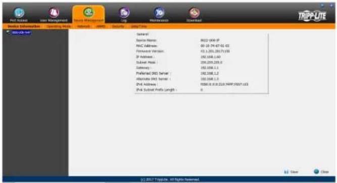
The following table describes the contents of the Device Information page.
| Item Description | |
| Device Name | To make it easier to manage installation that have more than one KVM connected to the network, you are given the option of entering a unique device name. To assign a device name for the KVM switch, simply type the desired name in this field (16 characters max). By default, the device name is the model name of the KVM. |
| MAC Address | The KVM's MAC address displays here. A MAC address label can also be found on the bottom panel of the console. |
| Firmware Version | Indicates the current IP firmware version. This firmware controls the IP functionality of the KVM switch, whereas a separate version, upgradeable via the Local Console OSD, controls the basic KVM and console functionality. New firmware files can be downloaded from triplite.com/support as they become available. You can reference this number to see if the version on the website is newer than that on your KVM. |
| IP Address The IPv4 address | s of the network interface is displayed here. |
| Subnet Mask The IPv4 Subnet | Mask of the network interface is displayed here. |
| Gateway The IPv4 Gateway | of the network interface is displayed here. |
| Preferred DNS Server The IPv4 Preferred DNS Server of the network interface is displayed here. | |
| Alternate DNS Server The IPv4 Alternate DNS Server of the network interface is displayed here. | |
| IPv6 Address The IPv6 address | of the network interface is displayed here. |
| IPv6 Subnet Prefix Length | The IPv6 Subnet Prefix Length of the first network interface is displayed here. |
7.2.13 Operating Mode
The Operating Mode sub-section allows the working parameters of the KVM to be set. The settings in this sub-section are described in the table below.
| Item Description | |
| Force All to Grayscale | When this checkbox is checked, all of the accounts in the installation will be forced to view the remote video in black and white. This can help improve keyboard and mouse response time on slower networks. |
| Enable Device List | When this checkbox is checked, the KVM switch will appear in the device list of the non-browser Windows and Java client main pages. If this checkbox is not checked, you will still be able to access the KVM via the non-browser clients, but you will have to manually type in the IP address instead of selecting it from the device list. |
| Console Keyboard Language | Select from the drop-down list the language of the keyboard that is connected to the KVM console port. This defaults at English US. |
7. Administration (continued)
7.2.14 Network
The Network sub-section is where the KVM's network settings are entered.
![Run Access User Management Service Information Operating Disk Networks JAPR Security Data/Time TRIPP-LTE WOLUB-ISP IP Provider ○ Invested ○ View Only ○ Insulated Service Port: Program: 3008 HTTPS: 361 HTTPS: 443 Prot Settings IP Address: ● Close IP Address automatically [SIN27] ○ Set IP Address manually (Set IP) IP Address: 0.0000 Subnet Mask: 0.0000 Default Gateway: 0.0000 Unit Server: ● Close DNS server address automatically ○ Set DNS server subset manually Preferred DNS server: 0.0000 Alternate DNS server: 0.0000 © 2017 TRIPP-LTE All Rights Reserved.](/content/2026/04/591621/images/a417739fdf8a7ae547f9dd8b71aebdf9eb0577b49b0c586d3a8ddc34e48ed603.jpg)
The settings in this sub-section are described in the table below.
Item Description
| IP Installer | The B020-Series KVM switch comes with an IP Installer application that allows Windows computers to easily view and edit the KVM's network settings. This section determines what access the IP Installer has to the KVM switch. Enabled - When selected, the IP Installer can locate the KVM switch on the network and display its current IP address. It also allows the IP Installer to be used to change the IP address of the KVM switch.View Only - When selected, the IP Installer can locate the KVM switch on the network and display its current IP address, but it cannot be used to change the IP address of the KVM switch disabled - When selected, the IP Installer cannot locate the KVM switch on the network, nor can it be used to change the IP address of the KVM switch. |
| Service Ports | This section allows you to set up port numbers that will be allowed by a firewall. If the port numbers on this page are not allowed access by the firewall, you will not be able to access the KVM switch. Valid entries for all of the service ports are from 1 to 65535. Note: You must enter a different port number for each field. If the KVM is connected to a network without a firewall, it doesn't matter what these ports are set to, as they will have no effect.Program - This is the port number that is used when accessing connected computers via the browser and non-browser Windows and Java clients. It is also the port number that is used when accessing virtual media. The default value is 9000. Note: This port number must match the port number in the non-browser Windows and Java clients when using them to connect to the KVM switch.HTTP - This is the port that is used for a browser login. The default value is 80.HTTPS - This is the port that is used for a secure browser login. The default is 443. |
| IPv4 Settings | The B020-Series KVM switch supports both IPv4 and IPv6. If you wish to use an IPv6 IP address, ignore this section.Obtain an IP Address Automatically (DHCP) - When this option is checked, the KVM switch will have its IP address assigned to it by a DHCP server upon booting up, and the remaining fields in this section will be grayed out. This option is checked by default.Set IP Address Manually (Fixed IP) - Check this option if you wish to assign an IP address to the KVM yourself. When checked, the settings fields below will be activated for you to edit.IP Address - Enter in the desired IP address here.Subnet Mask - Enter in the desired Subnet Mask here.Default Gateway - Enter in the desired Default Gateway here.Obtain DNS Server Address Automatically - When this option is checked, the KVM switch will have its DNS Server address assigned to it by a DHCP server upon booting up, and the remaining fields in this section will be grayed out. If you selected to set the IP address manually above, this option will be grayed out, and you will be required to enter the DNS Server address manually as well.Set DNS Server Address Manually - Check this option if you wish to assign a DNS Server address to the KVM yourself. When checked, the settings fields below will be activated for you to edit.Preferred DNS Server - Enter in the preferred DNS Server address here.Alternate DNS Server - Enter in the alternate DNS Server address here. This is an optional field. |
| IPv6 Settings | The B020-Series KVM switch supports both IPv4 and IPv6. If you wish to use an IPv4 IP address, ignore this section.Obtain IPv6 Address Automatically (DHCP) - When this option is checked, the KVM switch will have its IP address assigned to it by a DHCP server upon booting up, and the remaining fields in this section will be grayed out. This option is checked by default.Set IPv6 Address Manually (Fixed IP) - Check this option if you wish to assign an IP address to the KVM yourself. When checked, the settings fields below will be activated for you to edit.IPv6 Address - Enter in the desired IP address here.Subnet Prefix Length - Enter in the desired Subnet Prefix length here.Default Gateway - Enter in the desired Default Gateway here.Obtain DNS Server Address Automatically - When this option is checked, the KVM switch will have its DNS Server address assigned to it by a DHCP server upon booting up, and the remaining fields in this section will be grayed out. If you selected to set the IP address manually above, this option will be grayed out, and you will be required to enter the DNS Server address manually as well.Set DNS Server Address Manually- Check this option if you wish to assign a DNS Server address to the KVM yourself. When checked, the settings fields below will be activated for you to edit.Preferred DNS Server - Enter in the preferred DNS Server address here.Alternate DNS Server - Enter in the alternate DNS Server address here. This is an optional field. |
| Network Transfer Rate | This setting allows you to set the size of the data transfer stream to match your network, by setting the rate at which the KVM transfers data to remote computers. The range is from 4 to 99,999 KBps. The default is 99999. |
7. Administration (continued)
7.2.15 Advanced Network Management Settings
The ANMS sub-section is used to set up login authentication and authorization management from external sources. It is split up into two pages; Event Destination and Authentication, which are explained in the sections that follow.
Event Destination
The Event Destination page allows the KVM to be set up to record and send notifications of events that take place on the system. It allows you to enable and set up notification via SMTP, SNMP, Syslog Server and the Log Server.
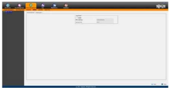
Log Server
In addition to the log that is built into the OSD, the KVM comes with an external Windows-based log server that can be installed on a computer. (See The Log Server section for details.) The Log Server section on this page is where the external log server can be enabled and set up for use. To do this, follow the steps below.
- Check the Enable checkbox in the Log Server section.
- In the MAC Address field, enter the MAC address of the computer that the log server resides on.
- In the Service Port field, enter in a port that the firewall will allow to be used to access the log server. The valid port range is between 1 and 65535. The default port number is 9001.
Note: The port number entered here must not be the same as any of the ports entered into the Network sub-section. (See Network section under Device Management for details.)
Authentication
The Authentication page allows remote authentication to be set up via RADIUS and LDAP/S.
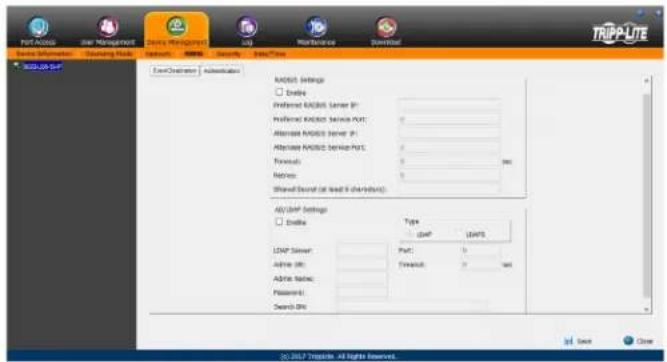
RADIUS Settings
To allow authentication and authorization for the B020-Series KVM Switch through a RADIUS server, do the following:
- Check the Enable check box in the RADIUS section.
- Fill in the IP addresses and port numbers for the Preferred and Alternate RADIUS servers.
- In the Timeout field, set the time in seconds that the B020-Series KVM Switch waits for a RADIUS server reply before it times out.
- In the Retries field, set the number of allowed RADIUS retries.
- In the Shared Secret field, key in the character string that you want to use for authentication between the B020-Series KVM Switch and the RADIUS Server.
- On the RADIUS server, set the entry for each user as su/xxxx, where xxxx represents the username assigned to the user in the KVM switch. User access rights will be the same as those that were assigned to them in the KVM switch. (See User Management section for details.)
7. Administration (continued)
LDAP / LDAPS Authentication and Authorization Settings
To allow authentication and authorization for the B020-Series KVM Switch via LDAP / LDAPS, refer to the information in the table, below:
| Character Meaning | |
| Enable | Put a check in the Enable checkbox to allow LDAP / LDAPS authentication and authorization. |
| LDAP / LDAPS Click to specify whether to use LDAP or LDAPS. | |
| LDAP Server IP and Port | Fill in the IP address and port number for the LDAP or LDAPS server. For LDAP, the default port number is 389; for LDAPS, the default port number is 636. |
| Timeout | Set the time in seconds that the B020-Series KVM Switch waits for an LDAP or LDAPS server reply before it times out. |
| Admin DN | Consult the LDAP / LDAPS administrator to ascertain the appropriate entry for this field. For example, the entry might look like this: ou=b020-u08-19-ip,dc=tripplite,dc=com |
| Admin Name Key in the LDAP administrator's username. | |
| Password Key in the LDAP administrator's password. | |
| Search DN Set the distinguished name of the search base. This is the domain name where the search starts for user names. | |
Note: If the LDAP Setting is enabled, the LDAP schema for MS Active Directory must be extended, or an OpenLDAP server must be installed and configured. (See LDAP Server Configuration, in the following section for details.)
LDAP Configuration — Active Directory
To allow authentication and authorization for the B020-Series KVM Switch via LDAP or LDAPS, the Active Directory's LDAP Schema must be extended so that an extended attribute name for the B020-Series KVM Switch – AccessRight – is added as an optional attribute to the person class (LDAP attribute example: B020-U08-19-IP-AccessRight).
- Authentication refers to determining the authenticity of the person logging in.
- Authorization refers to assigning permission to use the device's various features.
In order to configure the LDAP server, you will have to complete the following procedures: 1) Install the Windows 2003 Support Tools;
2) Install the Active Directory Schema Snap-in; and 3) Extend and Update the Active Directory Schema.
Install the Windows 2003 Support Tools
- On your Windows Server CD, open the Support → Tools folder.
- In the right panel of the dialog box that comes up, double click SupTools.msi.
- Follow along with the Installation Wizard to complete the procedure.
Install the Active Directory Schema Snap-in
- Open a Command Prompt.
- Key in regsvr32 schmmgmt.dll to register schmmgmt.dll on your computer.
- Open the Start menu. Click Run and key in mmc /a. Click OK.
- On the File menu of the screen that appears, click Add/Remove Snap-in, then click Add.
- Under Available Standalone Snap-ins, double click Active Directory Schema, click Close and click OK.
- On the screen you are in, open the File menu and click Save.
- For Save in, specify the C:\Windows\system32 directory.
- For File name, key in schmmgmt.msc.
- Click Save to complete the procedure.
Creating a Start Menu Shortcut Entry
To create a shortcut entry on the Start Menu for the Active Directory Schema, do the following:
- Right click Start; select: Open all Users → Programs → Administrative Tools.
- On the File menu, select New → Shortcut
- In the dialog box that comes up, browse to or key in the path to schmmgmt.msc (C:\Windows\system32\schmmgmt.msc) and click Next.
- In the dialog box that comes up, key in Active Directory Schema as the name for the shortcut, then click Finish.
7. Administration (continued)
Extend and Update the Active Directory Schema
Step 1 - Create a New Attribute:
a) Open Control Panel → Administrative Tools → Active Directory Schema.
![schemingmt - [Console Root\Active Directory Schema [LDAP.fra.com] \Classes] Console Root Active Directory Schema [LDAP.fra.com] Classes Attributes Name Sirtus Status acumPort Unicode String Active accountExport Large Integer/Interval Active accountInventory Unicode String Active aCSAggregatFokR... Large Integer/Interval Active aCSAbstaplerGDPEn... Large Integer/Interval Active aCSCacheTimeout Integer Active aCSDirection Integer Active aCDSBIDeadTime Integer Active aCDSBIPriority Integer Active aCDSBIPRefresh Integer Active aCDBEnableACSService Boolean Active aCDBEnablePSIPAccess... Boolean Active aCDBEnablePSIPAccess... Boolean Active aCDBEventLogLevel Integer Active aCDIIdentName Unicode String Active aCDIMaxAggregateAccess... Large Integer/Interval Active aCDIForDurationPerRow Integer Active aCDIFarureSUDUse Large Integer/Interval Active aCDIFarNoAccount... Integer Active](/content/2026/04/591621/images/d336353be63688cc2aca180cf032b5b7b3da305fae5645f53e85ff64d94dc387.jpg)
b) In the left panel of the screen that comes up, right-click Attributes:
c) Select New -Attribute.
d) In the warning message that appears, click Continue to bring up the Create New Attribute dialog box.
e) Fill in the dialog box according to the example below and click OK to complete step 1 of the procedure.
- Common Name – accessright
- LDAP Display Name - accessright
- Syntax – Unicode String
- Minimum - 1
• Maximum - 255
Note: The Unique X500 Object ID uses periods, not commas.
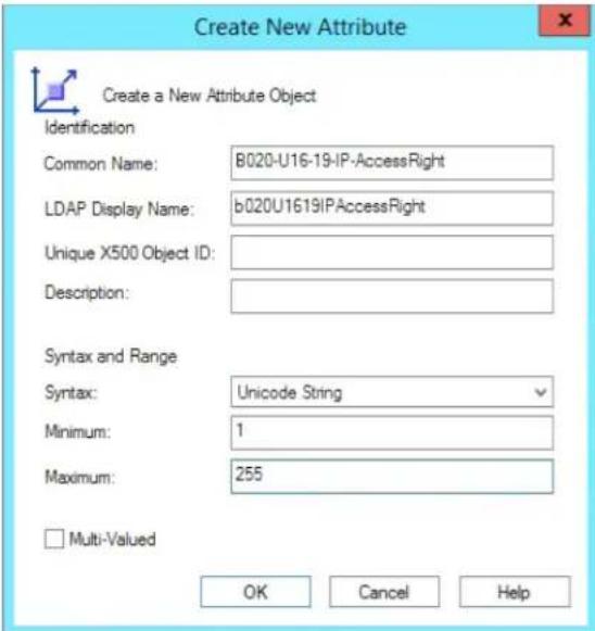
Window may appear different, depending on operating system.
Step 2 - Extend the Object Class With the New Attribute:
a) Open Control Panel → Administrative Tools → Active Directory Schema.
b) In the left panel of the screen that comes up, select Classes.
c) In the right panel, right-click person:
![schammgmt - [Console Root\Active Directory Schema [LDAP.tr.com] Classes] File Action View Favorites Window Help Console Root Active Directory Schema [LDAP.tr.com] Classes Attributes Name Type Status De organizationalPerson Type 88 Active Or organizationalRole Structural Active Or organizationUnit Structural Active Or packageRegistration Structural Active Pac person Type 88 Active Per physicallocation Structural Active Ph pKICertificateTemplate Structural Active PK1 pKEnrollmentService Structural Active PK1 posixAccount Auxiliary Active Abr posixGroup Auxiliary Active Abr printQueue Structural Active Prr postDelay Structural Active On](/content/2026/04/591621/images/3af0082010e852134bf4600768b092a35b5cbd4bb394e7df07d42661b9851923.jpg)
d) Select Properties; the person Properties page comes up with the General tab displayed. Click the Attributes tab.
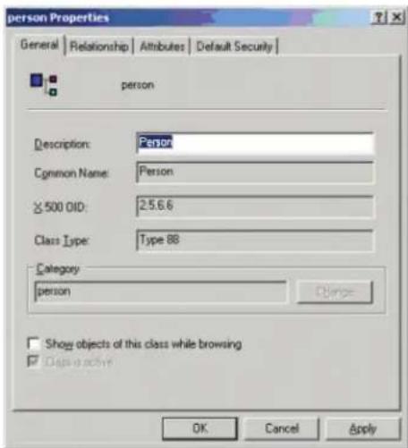
e) Select the Attributes tab and click the Add button:
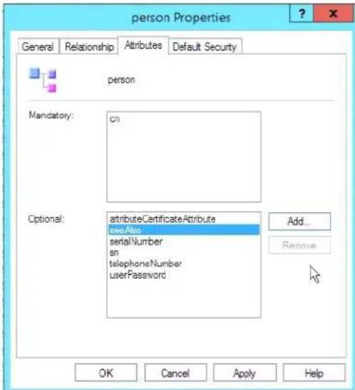
Window may appear different, depending on operating system.
7. Administration (continued)
f) In the list that comes up, select b020U1619IPAccessRight, then click OK to complete step 2 of the procedure.
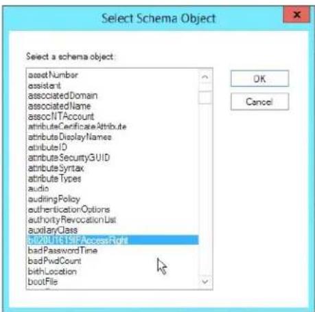
Window may appear different, depending on operating system.
Step 3 - Edit Active Directory Users With the Extended Schema:
a) Run ADSI Edit. (Installed as part of the Support Tools.)
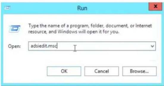
Window may appear different, depending on operating system.
b) Open Domain, and navigate to the cn=users dc=tripplite dc=com node.
c) Locate the user you wish to edit.
![Schroger - [ADSL E&R] D:\Users\123\100\100.hk123\DC-EndDC-Club (C:\Users) File Edit View Favorites Window Help Name Class Networked Name Chiconstrator user Chiconstrator, ChIcon, DC-End, DC-Club Chicon-Part Publishers group Chicon-Part Publishers, ChIcon, DC-End, DC-Club Chiconset13 user Chiconset13, ChIcon, DC-End, DC-Club Chiconset123 user Chiconset123, ChIcon, DC-End, DC-Club Chiconset466 user Chiconset466, ChIcon, DC-End, DC-Club ChiconSetAire group ChiconSetAire, ChIcon, DC-End, DC-Club ChiconSetAlphaire group ChiconSetAlphaire, ChIcon, DC-End, DC-Club ChiconSetAdmins group ChiconSetAdmins, ChIcon, DC-End, DC-Club ChiconSetComputer groups ChiconSetComputer, ChIcon, DC-End, DC-Club ChiconSetControls group ChiconSetControls, ChIcon, DC-End, DC-Club ChiconSetSuisse groups ChiconSetSuisse, ChIcon, DC-End, DC-Club ChiconSetUser groups ChiconSetUser, ChIcon, DC-End, DC-Club ChiconEnterprise Admins group ChiconEnterprise Admins, ChIcon, DC-End, DC-Club ChiconGroup Policy Creator On... group ChGroup Policy Creator Onors, ChIcon, DC-End, DC-Club ChiconPoint user group ChiconPoint User, ChIcon, DC-End, DC-Club ChiconServiceGroup group ChiconServiceGroup, ChIcon, DC-End, DC-Club ChiconH158 user ChiconH158, ChIcon, DC-End, DC-Club ChiconMgt user ChiconMgt, ChIcon, DC-End, DC-Club ChiconStudent star user ChiconStudent star, ChIcon, DC-End, DC-Club ChiconEdit and UI Servers group ChIconEdit and UI Servers, ChIconEdit, DC-End, DC-Club ChiconScheme Admins group ChonScheme Admins, ChIcon, DC-End, DC-Club ChIconStar user ChIconStar, ChIconStar, ChIconStar, DC-End, DC-Club ChiconProject_388966ab user ChOnProject_388966ab, ChIcon, DC-End, DC-Club ChiconData Centers group ChIconData Centers, ChIconData Centers, DC-End, DC-Club](/content/2026/04/591621/images/622cd0818d303f87b41e69be9151ddc921ec0ba47ad6ec09e9d324195e3eb33c.jpg)
d) Right-click on the user's name and select Properties.
e) On the Attribute Editor page of the dialog box that appears, select b020U1619IPAccessRight from the list.
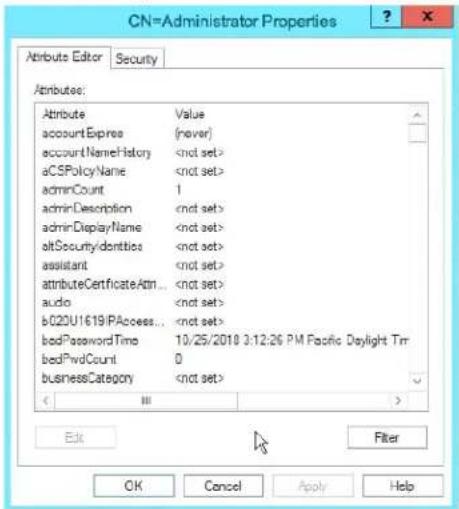
Window may appear different, depending on operating system.
f) Click Edit to bring up the String Attribute Editor:
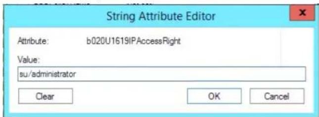
Window may appear different, depending on operating system.
g) Replace the value shown with su/xxxx, where xxxx represents the username assigned to the user in the KVM switch. User access rights will be the same as those that were assigned to them in the KVM switch. (See User Management section for details.)
h) Click OK. When you return to the Attribute Editor page, the b020U1619IPAccessRight entry now reflects the new permissions:
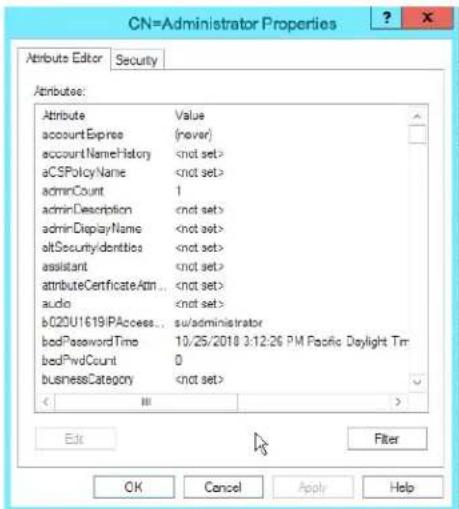
Window may appear different, depending on operating system.
i) Click Apply to save the change and complete the procedure.
j) Repeat Step 3 (Edit Active Directory Users With the Extended Schema) for any other users you wish to add.
7. Administration (continued)
OpenLDAP Server
OpenLDAP is an Open source LDAP server designed for UNIX platforms. A Windows version can be downloaded from: http://download.bergmans.us/openldap/openldap-2.2.29/openldap-2.2.29-db-4.3.29-openssl-0.9.8awin32_Setup.exe.
OpenLDAP Server Installation
After downloading the program, launch the installer, select your language, accept the license and choose the target installation directory. The default directory is:
c:\Program Files\OpenLDAP.
When the Select Components dialog box appears, select install BDB-tools and install OpenLDAP-slapd as NT service, as shown in the diagram, below:
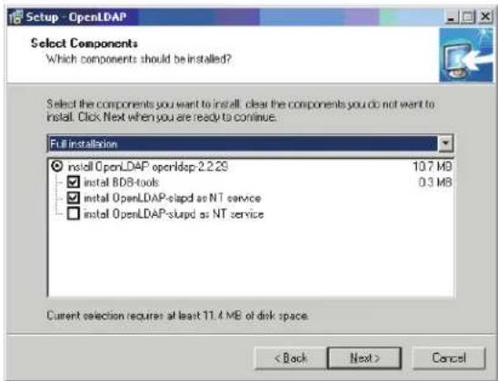
OpenLDAP Server Configuration
The main OpenLDAP configuration file, slapd.conf, has to be customized before launching the server. The modifications to the configuration file will do the following:
- Specify the Unicode data directory. The default is ./ucdata.
- Choose the required LDAP schemas. The core schema is mandatory.
- Configure the path for the OpenLDAP pid and args start up files. The first contains the server pid, the second includes command line arguments.
- Choose the database type. The default is bdb (Berkeley DB).
- Specify the server suffix. All entries in the directory will have this suffix, which represents the root of the directory tree. For example, with suffix dc=tripplite,dc=com, the fully qualified name of all entries in the database will end with dc=tripplite,dc=com.
- Define the name of the administrator entry for the server (rootdn), along with its password (rootpw). This is the server's super user. The rootdn name must match the suffix defined above. (Since all entry names must end with the defined suffix, and the rootdn is an entry)
An example configuration file is provided in the figure, below:
ucdata-path /ucdata
include ./schema/core.schema
pidfile /run/slapd.pid
argsfile ./run/slapd.args
database bdb
suffix "dc=tripplite, dc=com"
rootdn "cn=Manager, dc=tripplite, dc=com"
rootpw secret
directory /data
Starting the OpenLDAP Server
To start the OpenLDAP Server, run slapd (the OpenLDAP Server executable file) from the command line. slapd supports a number of command line options, the most important option is the d switch that triggers debug information. For example, a command of slapd -d 256 would start OpenLDAP with a debug level of 256, as shown in the following screenshot:
Note: For details about slapd options and their meanings, refer to the OpenLDAP documentation.
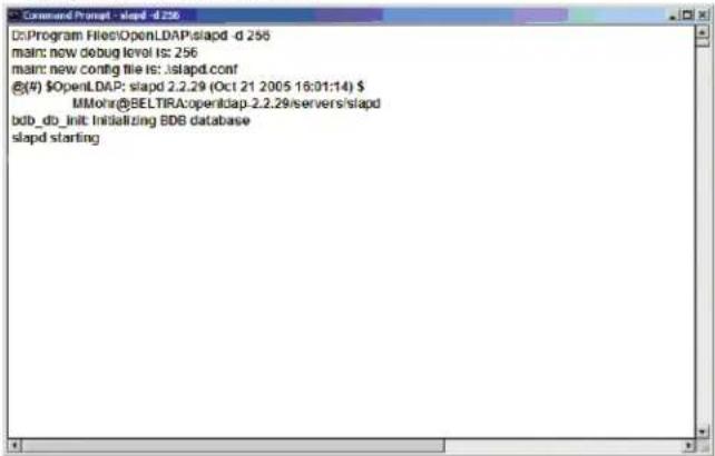
Customizing the OpenLDAP Schema
The schema that slapd uses may be extended to support additional syntaxes, matching rules, attribute types, and object classes. In the case of the B020-Series KVM Switch, the B020-Series KVM Switch User class and the permission attribute are extended to define a new schema. The extended schema file used to authenticate and authorize users logging in to the B020-Series KVM Switch is shown in the figure, below:

antibuzetype (1361412131711422
NAME 'permission'
EQUALITY case[ignore Match
SUBSTR caseignoreSubstringsMatch
SYNTAX 1.3.6 14 1.1466 115.121 1 15
SINGLE-VALUE(
objectclass (1.3.6.14.1.21317.11.4.12
NAME 'User'
SUP organizationalPerson
STRUCTURAL
MAY (permission)'s user Certification
7. Administration (continued)
LDAP DIT Design and LDIF File
LDAP Data Structure
An LDAP Directory stores information in a tree structure known as the Directory Information Tree (DIT). The nodes in the tree are directory entries, and each entry contains information in attribute-value form. An example of the LDAP directory tree for the B020-Series KVM Switch is shown in the figure below:

flowchart
graph TD
    A["dc = com"] --> B["dc = triplite"]
    B --> C["cn = Manager"]
    B --> D["ou => Users"]
    D --> E["cn = steve"]
    D --> F["cn = judy1"]
    D --> G["cn = aaa"]
DIT Creation
The LDAP Data Interchange Format (LDIF) is used to represent LDAP entries in a simple text format (please refer to RFC 2849). The figure below illustrates an LDIF file that creates the DIT for the B020-Series KVM Switch directory tree (shown in the figure in the previous section).

do: de=tripplite, de=rcn objectclass: top objectClass: doObject objectClass: organization
dn: cn=Manager, dc=ingspike, dc=com objectclass: top objectclass: person objectclass: organizationalPerson cn: Manager cn: Manager
dn: cu=Users, de=tripplito, de=com objectclass: top objectclass: organizationalUnit out: Users
dn: cn=store,ou=Users, dc=txipplate, dc=com objectclass: top objectclass: person objectclass: organizationalPerson objectclass: User cn: store sn: store pumission w,v,p,i,c,l userPassword password on: Users
The following figure illustrates an LDIF file that defines the OpenLDAP group for the B020-Series KVM Switch.
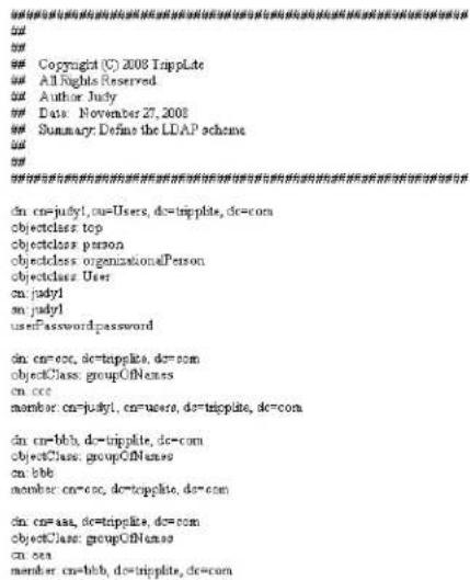
Using the New Schema
To use the new schema, do the following:
-
Save the new schema file (e.g., B020-Series KVM switch. schema) in the /OpenLDAP/ schema/ directory.
-
Add the new schema to the slapd.conf file, as shown in the figure:
-
Restart the LDAP server.
-
Write the LDIF file and create the database entries in init.Idif with the Idapadd command, as shown in the following example: Idapadd -f init.Idif -x -D "cn=Manager,dc=tripplite,dc=com" -w secret
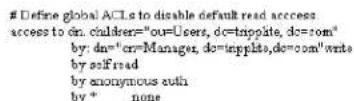


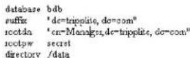
7. Administration (continued)
7.2.16 Security
The following section describes the settings found in the Security sub-section.
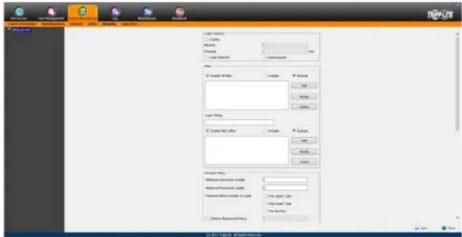
Login Failures
The Login Failures section allows you to set up the parameters for what occurs when an account fails to login successfully. To enable the settings entered here, check the Enable checkbox. The table below describes the settings found in this section.
Note: When the Login Failures settings are disabled, there is no restriction on the number of login failures. It is strongly recommended that you enable these features, and that both the Lock Client PC and Lock Account settings are enabled.
| Setting Description | |
| Allowed | Determines the number of failed login attempts an account gets before they are prevented from accessing the KVM switch. |
| Timeout | Determines the amount of time that the user is prevented from accessing the KVM switch after exceeding the maximum number of failed login attempts. |
| Lock Client PC | When this checkbox is checked, the computer used to unsuccessfully access the KVM will be locked out after exceeding the maximum number of failed login attempts. Note: This feature blocks the computer using its IP address. If the computer IP address is changed, it will be able to access the KVM in spite of this setting. |
| Lock Account | When this checkbox is checked, the account used to unsuccessfully access the KVM will be locked out after exceeding the maximum number of failed login attempts. |
Filtering
To enable IP and/or MAC filtering, click the IP Filter Enable and/or MAC Filter Enable checkbox. There are a maximum of 100 filters allowed for each.
- If the include button is checked, all the addresses within the filter range are allowed access to the B020-Series KVM Switch; all other addresses are denied access.
- If the exclude button is checked, all the addresses within the filter range are denied access to the B020-Series KVM Switch; all other addresses are allowed access.
IP Filtering
To add an IP filter:
- Check the IP Filter Enable check box.
- Click Add. A dialog box similar to the one below appears:
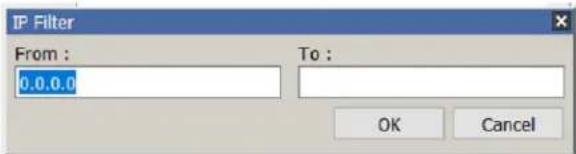
- To filter a range of IP addresses, enter the starting IP address in the From field, and the ending IP address in the To field.
- After filtering in the addresses, click OK.
- Repeat these steps for any additional IP addresses you want to filter.
To delete an IP filter:
Select the desired IP filter from the list and click Delete.
To modify an IP filter:
- Select the desired IP filter from the list and click Modify. A Modify dialog box similar to the Add dialog box will appear.
- Delete the old start IP address and replace it with the new one.
- Delete the old end IP address and replace it with the new one. Click OK.
Note: To block a computer from accessing the B020-Series KVM Switch, you do not need to filter both its IP address and its MAC address. Any computer blocked by an IP filter will be denied access to the KVM switch, even if the computer is allowed to access the KVM switch under the MAC filters that are set up.
7. Administration (continued)
Login String
The Login String allows the KVM's IP address to be more secure by adding extra text to the end of it. When text is entered into the Login String field, users will need to include a forward slash (/) and the Login String at the end of the URL to access the KVM switch. For example, if a Login String of abcdefg is entered, the user must enter a URL such as 192.168.0.126/abcdefg.
The following characters are allowed in the login string:
0 through 9, a through z, A through Z, \~ ! @\$^&*()_+'<>,.|
The following characters are not allowed:
%":/?#[Space]
Note: If a Login String is not entered, anyone can access the KVM switch using the IP Adress alone, making the installation less secure.
MAC Filtering
To add a MAC filter:
- Click Add. A dialog box similar to the one below appears:
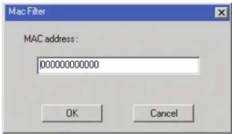
- Type in the desired MAC address and click OK.
- Repeat these steps for any additional MAC addresses you want to filter.
To delete a MAC filter:
Select the desired MAC filter from the list and click Delete.
To modify a MAC filter:
- Select the desired MAC filter from the list and click Modify. A Modify dialog box box appears.
- Delete the old address and replace it with the new one. Click OK.
Note: To block a computer from accessing the B020-Series KVM Switch, you do not need to filter both its IP address and its MAC address. Any computer blocked by a MAC filter will be denied access to the KVM switch, even if the computer is allowed to access the KVM switch under the IP filters that are set up.
If any filters have been configured, they appear in the IP Filter and/or MAC Filter list boxes.
Account Policy
The Account Policy section allows rules for usernames and passwords to be regulated. The settings in this section are described in the table below.
| Item Description | |
| Minimum Username Length | Sets the minimum number of characters required for each username. Values from 1 to 16 can be entered. |
| Minimum Password Length Sets | the minimum number of characters required for each password. Values can be from 0 to 16. |
| Password Must Contain at Least | One Uppercase – Checking this box will require that each password contain one uppercase letterOne Lowercase – Checking this box will require that each password contain one lowercase letterOne Number – Checking this box will require that each password contain one numberNote: Current usernames and passwords are not affected when these settings are changed. Only usernames and passwords that are created after these settings have been changed must follow the rules. |
| Enforce Password History | This policy setting determines the number of unique new passwords that must be associated with a user account before an old password can be reused. User-specified number from 0 through 24. |
Encryption
This section allows you to set different encryption settings for the Keyboard/Mouse, Video and Virtual Media functions of the KVM switch. You can choose any combination of encryption methods (DES, 3DES, AES and/or RC4), you can choose to randomly switch between them or you can choose no encryption at all. Although enabling encryption will add more security to you installation, it can also slow down system performance (mouse, keyboard, video), with the following having the most impact:
- RC4 impacts performance the least out of the four encryption methods. DES is second to least in impact, followed by 3DES and AES.
- Of all the possible combinations, a combination of RC4 and DES impacts performance the least.
7. Administration (continued)
Working Mode
The Working Mode section allows you to enable/disable operation features of the KVM switch. The table below describes the available settings.
| Setting Description | |
| Enable ICMP When this box is checked, the KVM switch can be pinged. If it is not checked, the KVM cannot be pinged. | |
| Enable Multiuser Operation | When this box is checked, multiple accounts can log onto the same bus at the same time (see Bus Info section under Control Panel in Remote Session Operation for details). If not selected, the KVM switch can only be simultaneously accessed by the number of users the unit has buses for. B020-U08-19-IP and B020-U16-19-IP have 2 buses each (1 local, 1 remote). |
| Browser Service | When this box is checked, browser access to the KVM switch can be limited by selecting one of the three options in the drop-down menu.· Disable Browser – Browser access is disabled completely.· Disable HTTP – Browser access is permitted, but only when using a HTTPS URL.· Disable HTTPS – Browser access is permitted, but only when using a HTTP URL. |
Private Certificate
When logging into the KVM switch over a secure (SSL) connection, a certificate is required to ensure you are logging into a secure site. If a certificate is not recognized as secure, you will be prompted each time you log in to verify you want to continue to the website. This section allows you to import an Encryption Key and Certificate. To import an Encryption Key and Certificate, follow the steps below.
- Click the Browse button to the right of Private Key, browse to where your private encryption key file is located, and then select it.
- Click the Browse button to the right of Certificate, browse to where your certificate file is located, and then select it.
- Click the Upload button to complete the procedure.
Note: Both the Private Key and Certificate must be imported at the same time. Clicking the Restore Default button returns the KVM to the default certificate that came installed on it.
Certificate Signing Request
The Certificate Signing Request section provides an automated way of obtaining and installing a CA signed SSL server certificate. To perform this operation, follow the steps below.
- Click the Create CSR button. The following dialog box appears.
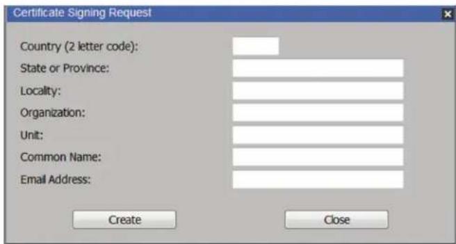
7. Administration (continued)
- Fill in the form with the appropriate information for your company. The table below is an example of a filled out form.
| Field Example | |
| Country (2 letter code) TW | |
| State or Province Taiwan | |
| Locality Taipei | |
| Organization Your Company, Ltd. | |
| Unit Techdoc Department | |
| Common Name | www.mycompany.com Note: This entry must be the exact domain name of the site that you want the certificate to be valid for. If the site's domain name is www.mycompany.com, and you enter mycompany.com, the certificate will not be valid. |
| Email Address administrator@yourcompany.com | |
- When all fields have been filled out (all fields are required), click the Create button.
- Click the Get CSR button, and then save the certificate file to a convenient location on your computer. This is the file that you give to the third party CA to apply for their signed SSL certificate.
- After you have received the certificate from the third party CA, save it to a convenient location on your computer. In the Certificate Signing Request section of the Security page, click the Browse button and navigate to and select the certificate.
- Click the Upload button.
Note: When uploading the file, the KVM checks to make sure the specified information still matches. If it does, the file is accepted. If it does not match, the file will be rejected. If you want to remove the certificate (e.g. to replace it with a new one because of a domain name change), click the Remove CSR button.
7.2.17 Date/Time
The Date/Time page allows the user to set the date and time parameters for the KVM switch. The following section describes the settings on this page.
![Time Zone [OMT-12:00] Enhvetak Kwajaalen Daylight Savings Time Data February < 2009 > February 2009 Su Mo Tu Wa Th Fr Sg 1 2 3 4 5 6 7 8 9 10 11 12 13 14 15 16 17 18 19 20 21 22 23 24 25 26 27 28 Time 15 : 59 : 02 Set Network Time Enable sure adjustment Preferred time server AU | mtp1.oss.mu.02.AU Preferred custom server IP 0.0.0.0 Alternate time server AU | mtp1.oss.mu.02.AU Alternate custom server IP 0.0.0.0 Adjust time every: days SELECT TIME/NAVY](/content/2026/04/591621/images/d52d4b18da7b6f0ef8a21319b463eed41d45e825a9f8b636a1efd9517bfda32d.jpg)
Time Zone
- Select the Time Zone and City that most closely resembles where the KVM switch is in using the drop-down menu at the top of this section.
- If your area uses Daylight Savings Time, check the Daylight Savings Time checkbox.
To manually set the date and time, do the following:
- In the Date section, select the current month using the dropdown menu.
- If needed, click the < or > buttons in the Date section to move backward or forward to the correct year.
- In the calendar in the Date section, click on the current day.
- In the Time section, enter in the current time using the 24 hour HH:MM:SS format.
- Click the Set button in the Time section to apply your changes.
Network Time
To have the time automatically synchronized to a network time server, do the following:
- Check the Enable Auto Adjustment checkbox.
- Select a time server from the Preferred Time Server drop-down list; or, check the Preferred Custom Server IP checkbox and enter in the IP of your preferred time server.
- If desired, repeat step two to enter an Alternate Time Server.
- Key in the desired number of days between synchronization in the Adjust Time Every _ Days field.
- Click the Adjust Time Now button to synchronize immediately.
7. Administration (continued)
7.2.18 Log
The B020-Series KVM switches log all the events that take place and writes them to a log file. The Log section is split into two sub-sections; Log Information and Notification Settings.
Log Information
The Log Information sub-section is where you can view the contents of the built-in log file. When opened, a page similar to the one below appears.
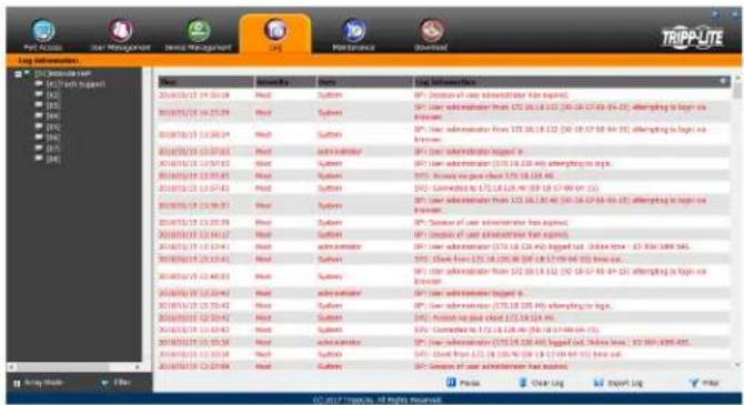
The Log Information page can store up to 512 events, at which time the oldest files are deleted and replaced with newer files. The records it displays show the Time, Severity, User and Log Information associated with the event. At the bottom of the screen are four icons, whose functionality is described below.
- Pause – Clicking the Pause button stops new events from being displayed in the Log Information page. When clicked, the icon changes to Resume. Click Resume to allow events to be displayed again.
- Clear Log – Clicking the Clear Log button will clear the records displayed in the Log Information page.
- Export Log – Clicking the Export Log button will allow you to export and save the log file to your computer.
- Filter – Clicking the Filter button opens the Filter settings, shown below, which allow you to display only records that match the filter settings entered. The filter settings are described in the table below.
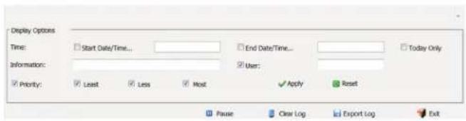
Field Example
| Time | The Time filter settings allow you to display only those records that occurred at a specific time. Below are the options.Today Only – Check the Today Only checkbox and click the Apply button to display only those events that occurred on today's date.Start Date/Time – Check the Start Date/Time checkbox and click in the field to the right of it to bring up a calendar that allows you to select a desired date and time. Click the Apply button to display all of the events that occurred between the date/time entered into the Start Date/Time field and the present date/time.End Date/Time – This setting works in conjunction with the Start Date/Time field. Check the Start Date/Time checkbox and click in the field to the right of it to bring up a calendar that allows you to select a desired date and time. Check the End Date/Time checkbox and click in the field to the right of it to bring up a calendar that allows you to select a desired date and time. Click the Apply button to display all of the events that occurred between the date/time entered into the Start Date/Time field and the date/time entered into the End Date/Time field. |
| Information | The Information field allows you to type in a key word or string, and display only those records that contain the search term. Simply type in a search term and click the Apply button. |
| User | The User field allows you to type in a user name, and display only those records that contain the text that you entered in the User field. To filter by User, you must check the User checkbox, type in a search term, and then click the Apply button. |
| Priority | The Priority fields allow you to filter by the Priority of the event being recorded; Least, Less or Most. To filter by Priority, check the Priority checkbox, then check the Priority level checkbox(es) that you wish to filter by, and then click the Apply button. |
| Reset | Click the Reset button at any time to clear any filter settings that were entered and display all events. |
| Exit | Click the Exit button to close the Filter settings. |
7. Administration (continued)
7.2.19 Maintenance
The Maintenance section is used to upgrade the B020-Series KVM Switch's firmware.
Note: Super Administrators are the only users who are guaranteed access to the Maintenance section of the KVM. Administrators and Users can only access this function if they are given permission.
The Main Screen
The Maintenance section can be used to upgrade the KVM, backup/ restore system configuration and account information, ping network devices, and restore the KVM's default values. When selected, the Maintenance section opens with the Upgrade Main Firmware subsection displayed.
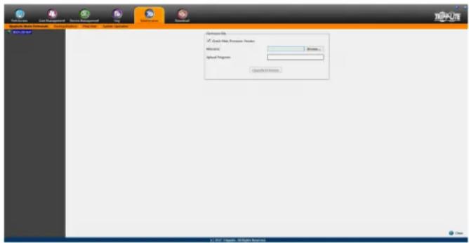
Upgrade Main Firmware
The Upgrade Main Firmware sub-section is used to upgrade the firmware of the KVM switch. As firmware upgrades become available, they can be found on tripplite.com/support. To upgrade the KVM firmware, follow the steps below.
- Go to tripplite.com/support to download the most current firmware and save it to a computer that is not connected to the KVM switch.
- Logon to the OSD, and navigate to the Maintenance section, which will open with the Upgrade Main Firmware sub-section page displayed.
- By default, the Check Main Firmware Version box is checked, which causes the KVM to check to see if the current firmware is newer than that of the firmware file you are using to upgrade the KVM. If the current version is newer, you will not be allowed to continue with the upgrade. If you wish to perform a firmware upgrade without checking to see if the current firmware version is newer than the upgrade file, simply uncheck this checkbox.
- Click the Browse button, and then navigate to and select the firmware upgrade file you downloaded from the Tripp Lite website. When selected, the Upgrade Firmware button becomes active.
- Click the Upgrade Firmware button to begin the firmware upgrade. As the upgrade proceeds, progress is shown in the Upload Progress bar.
- When the upload is complete, a pop-up appears stating System will reboot in a few seconds. The KVM switch will reboot (this may take a few minutes), and the upgrade will be complete. In the event of a firmware upgrade failure, see the Main Firmware Upgrade Recovery section below.
Main Firmware Upgrade Recovery
Should the KVM firmware upgrade procedure fail, and the switch becomes unusable, follow the steps below to restore the KVM.
- Power off the KVM.
- Press and hold the Reset switch on the front of the unit.
- Power on the KVM while holding down the Reset switch.
- The KVM will be restored to the originally installed firmware version. You will now be able to access the KVM switch and try upgrading the firmware again.
Backup/Restore
The Backup/Restore subsection allows you to backup and restore the KVM switch configuration and user profile information.
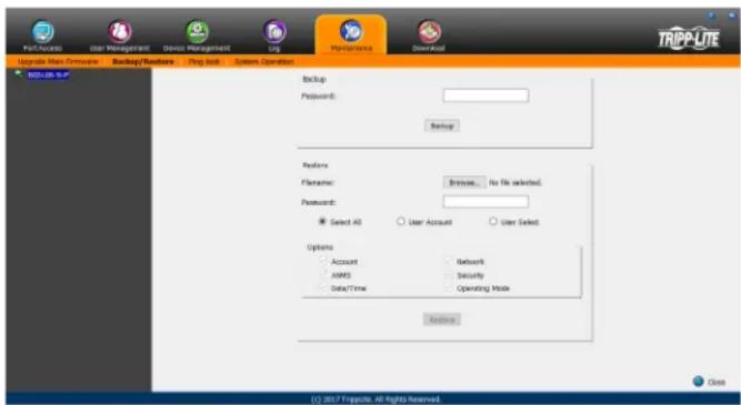
Backup
To create a backup of the KVM switch, follow the steps below.
- Key in a password in the Password field. Note: Setting a password is optional. If you do not wish to use a password, you can skip this step.
- Click the Backup button.
- A pop-up appears asking you to save the backup file. Browse to a desired location on your computer to save the file to.
Restore
To restore the KVM switch using a backup file, follow the steps below.
- Click on the Browse button to the right of the filename field, and then navigate to and select the backup file.
- If you set up a password when creating the backup file, enter it in the Password field.
- Select as many of the options that are presented as you wish to restore, and then click the Restore button. Once complete, a message appears to inform you that the procedure succeeded.
7. Administration (continued)
Ping Host
The Ping Host subsection lets you check the network status of devices on the KVM installation.
To ping a device, follow the instructions below.
- Key in the IP address or Host Name of the device into the IP address/Host Name field.
- Click the Ping button. The ping results will be displayed in the Results section.
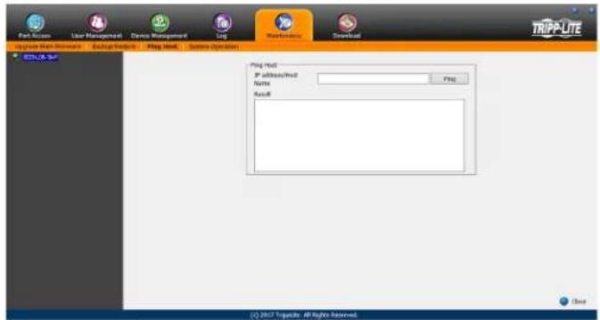
System Operation
The System Operation sub-section allows you to clear port names, and reset the KVM configuration settings to their default values.
The functions available in the System Operation page are explained in the table below.
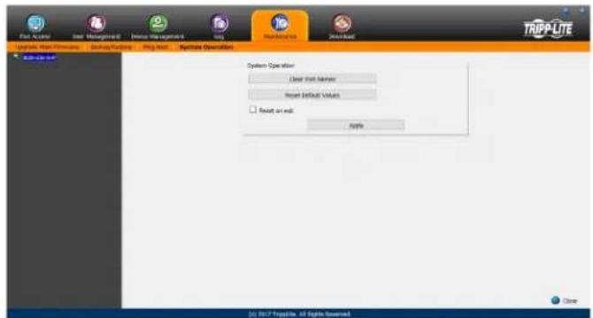
Field Example
| Clear Port Names | Click this button to clear all of the port names on the installation and restore them to their default values. Upon clicking this button, you will be prompted to confirm that you wish to clear all port names. Click Yes to proceed. |
| Reset Default Values | Click this button to undo all configuration changes that have been made to the KVM, and restore them to the factory default settings. This does not affect port names, account information or network information. Upon clicking this button, you will be prompted to confirm that you wish to proceed. Click Yes to proceed. |
| Reset on Exit | Check this box and click the Apply button to have the KVM switch reset itself and implement all new settings upon logging out. (Following the reset, allow approximately 30 to 60 seconds before logging back into the KVM.)If you change the IP address of the KVM, the Reset on Exit checkbox is automatically checked. To prevent the KVM from resetting and saving the new IP address, uncheck this box. Note: Un-selecting this checkbox will only cause the new network settings to be ignored for one logout. When you log back in, the changes you made still appear in the Network settings fields, and the Reset on Exit checkbox is once again checked. To ensure that these settings don't get changed to something you don't want, always make sure that you leave the Network settings page with the correct information entered in. |
7.2.20 Download
The Download icon is used to download non-browser AP versions of the Windows and Java Clients, as well as the Log Server. Selecting this tab will open a drop-down list of the programs that are available for download.
Note: If you have not been given access to one of these applications, you will not be able to download it.
Click on the Download icon and select the program you want to download. Save it to a convenient location on your hard disk and run it from there.
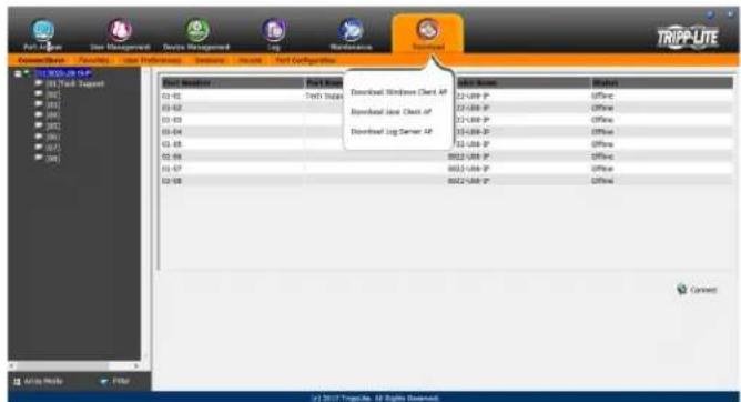
7. Administration (continued)
7.3 Log Server
The Windows-based Log Server is an administrative utility that records all the events that take place on selected KVM switch units and writes them to a searchable database. This chapter describes how to install and configure the Log Server.
Note: The Log Server requires the Microsoft Jet OLEDB v4.0 or higher driver in order to function properly.
To install the Log Server, do the following:
- From the computer that you want to use to host the Log Server, open the CD that came with the KVM switch and open the Log Server Installer file. If any security warning dialog boxes appear, ignore them and click Run or Open. A Log Server setup screen appears.
-
Click the Next button, and then follow the on-screen instructions to complete the installation and have the Log Server program icon placed on your desktop.
-
After installation, and before opening the Log Server for the first time, go to the ANMS page in the Web Management Interface or Remote OSD and enter the MAC address of the computer you installed the Log Server on and an access port that can be used to get through a firewall. (See page 49 for the Web Management Interface ANMS or page 34 for the Remote OSD ANMS.)
-
Double-click the Log Server desktop icon. The first time you open the Log Server, a screen similar to the one below appears:
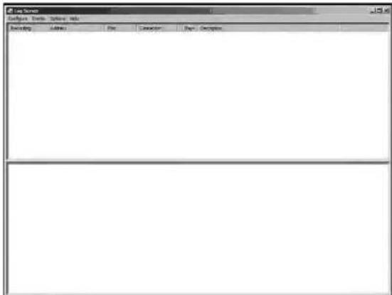
The screen is divided into three components:
• A Menu Bar at the top.
- A panel that will contain a list of all KVM switch units in the middle.
- A panel that will contain an Events List at the bottom.
Menu Bar
The Menu bar consists of four drop-down menus:
- Configure
- Events
- Options
- Help
Configure
The Configure menu consists of three functions; Add, Edit and Delete.
Add
Select the Add function when you need to add a new KVM switch to the list of units that the Log Server records events for.
Note: You must first add a KVM switch via the Add function before the Log Server can start recording its events.
When you open the Add function the following dialog box will appear:
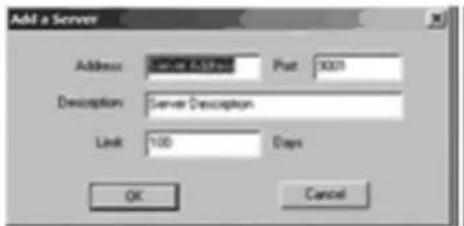
Descriptions of the fields in this dialog box are shown in the table:
| Field Description | |
| Address This can either be the IP address of the KVM switch or its DNS name (if the network administrator has assigned it a DNS name). This value must be entered into the ANMS settings screen in order for the KVM switch to communicate with the Log Server. (See page 49 for the Web Management Interface ANMS or page 34 for the Remote OSD ANMS.) | |
| Port Key in the port number that was specified in the Log Server portion of the ANMS settings screen. If this differs from the port entered in the ANMS settings screen, the Log Server will not be able to communicate with the KVM switch. | |
| Description This field is provided so that you can enter in additional information that will help differentiate this KVM switch from all other KVMs that the Log Server is recording information for. | |
| Limit This specifies the number of days that an event is kept in the database before it can be deleted. To remove all events that have passed the expiration date set in this field, use the Maintenance function in the Events menu. (See page 53 for details on the Maintenance function.) |
Edit
Select the Edit function when you need to change the information for an existing KVM switch. To edit an existing KVM, simply highlight it in the Log Server list and open the Edit function from the Configure menu. A dialog box will appear that shows the exact information that was entered for the KVM when it was added using the Add function. Edit this information and click OK.
Delete
To delete a KVM switch, simply highlight it in the Log Server list and open the Delete function from the Configure menu. A dialog box will appear which will display the KVMs information and ask you to click OK to delete it. If you want to remove it from the list of KVMs being tracked by the Log Server, click OK.
7. Administration (continued)
Events
The Events menu consists of two items; Search and Maintenance.
Search
Search allows you to search for events containing specific words or strings. When you access this function, a screen similar to the one that follows appears:
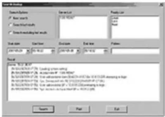
A description of the items from the Search screen is given in the table:
| Item Description | |
| Search Options | New search: When selected, the search is performed on all the events in the database for the selected KVM.Search last results: This is a secondary search performed on the events that resulted from the last search.Search excluding last results: This is a secondary search performed on all the events in the database for the select-ed KVM excluding the events that resulted from the last search. |
| Server List KVM switches are listed in the Log Server list according to their IP address. Select the unit that you want to perform the search on from this list. You can select more than one unit for the search. If no units are selected, the search is performed on all of them. | |
| Priority List Determines what types of search results are displayed, according to their level of importance to the security of the installation; Most, Medium or Least. If nothing is selected, all results will display, and they will be color-codes according to level of importance:Most important: Entries highlighted in red are the most relevant to the security of the installation.Medium importance: Entries highlighted in blue are somewhat relevant to the security of the installation.Least importance: Entries highlighted in black are least relevant to the security of the installation. | |
| Start Date Select the date that you want the search to start from. The format follows the MM/DD/YYYY convention (e.g. 11/04/2005). | |
| Start Time Select the time that you want the search to start from. | |
| End Date Select the date that you want the search to end. The format follows the MM/DD/YYYY convention (e.g. 11/04/2005). | |
| End Time Select the time that you want the search to end. | |
| Pattern Key in text here that you want the search to filter the events by. | |
| Results The events that matched your search terms are listed here. | |
| Search After you have entered in all of your search terms, click this button to start the search. | |
| Print Click this button to print the search results. | |
| Export Click this button to export search results as a text file. | |
| Exit | Click this button to exit the Search dialog box. |
Maintenance
This function allows the Administrator to remove all records that have passed their expiration limit. (See Limit on page 52 for details.) In order to delete old files from the log server, the maintenance function must be performed.
Options
The Options menu consists of only one function; Network Retry.
Network Retry
Network Retry allows you to set the number of seconds that the Log Server should wait before attempting to connect in the event that the previous connection attempt failed. When you click this item, a dialog box appears:
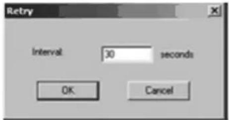
Key in the desired number of seconds and click OK to finish.
Help
The Help menu consists of two options; Contents and About Log Server.
Contents
Selecting the Contents function will bring up an online help file. The help file contains instructions about how to setup, operate and troubleshoot the Log Server.
About Log Server
Selecting the About Log Server option will pull up a dialog box that gives you the version number of the Log Server.
The Log Server Main Screen
The Log Server Main Screen is divided into two main panels; an upper (List) panel that displays all of the KVM switches that have been added to the Log Server and a lower (Event) panel that displays the log events for the currently selected KVM. To select a KVM from the list, simply click on it.
7. Administration (continued)
The List Panel
The List panel contains the following fields:
| Field Description | |
| Recording | Determines whether the Log Server records log events for the corresponding KVM switch. If this checkbox is checked, the field displays Recording, and log events are recorded. If this checkbox is not checked, the field displays Paused, and log events are not recorded for the corresponding KVM.Note: Even if a KVM is not currently selected, if its Recording checkbox is checked, the Log Server will still record its log events. |
| Address | This is the IP address or DNS name that was given to the KVM switch when it was added to the Log Server. |
| Port | This is the port number that was assigned to the KVM switch when it was added to the Log Server. |
| Connection | If the Log Server is connected to the corresponding KVM switch, this field displays Connected. If it is not connected, this field displays Waiting. A connection status of Waiting means that the Log Server is not communicating with the KVM, and will not record its events. This occurs when the Log Server's MAC address and/or port number have not been set properly. The MAC address and port for the Log Server computer must be entered into the KVM's ANMS settings screen. In addition, the KVM's IP address and port must be entered when adding it to the Log Server. If the port numbers in the ANMS menu and the Log Server do not match, the two will not be able to communicate. |
| Days | This field displays the number of days that the KVM's log events are to be kept in the database before it is eligible for deletion. |
| Description | This field displays the descriptive information entered for the corresponding KVM switch when it was added to the Log Server. |
The Event Panel
The lower panel displays event information for the currently selected KVM switch.
8. Specifications
| Specification B020-U08-19-IP B020-U16-19-IP | ||
| Computer Ports HD18 Female (8) HD18 Female | (16) | |
| KVM Cable Kit Model P778-Series P778-Series | ||
| KVM Cable Kit Connectors KVM Side: HD18 Male | Computer Side: HD15 Male, USB-A Male, PS/2 Male (2) | KVM Side: HD18 MaleComputer Side: HD15 Male, USB-A Male, PS/2 Male (2) |
| Included Cable Kits P778-006 6 ft. Cables (2) P778-006 6 ft. Cables (2) | ||
| Port Selection OSD, Hotkey, Pushbutton (Local Console Only) OSD, Hotkey, Pushbutton (Local Console Only) | ||
| External Console Ports HD18 Male, USB-A Female HD18 Male, USB-A Female | ||
| External Console Cable Yes | Yes | |
| External Console Cable Connectors | KVM Side: HD18 FemaleComputer Side: HD15 Female, USB-A Female (2), PS/2 Female (2) | KVM Side: HD18 FemaleComputer Side: HD15 Female, USB-A Female (2), PS/2 Female (2) |
| Additional USB Ports | 1 | 1 |
| Additional USB Port Version | 1.1 | 1.1 |
| Daisy-Chain Port | DB25 Male | DB25 Male |
| Max Connections via Daisy-Chain | 256 | 264 |
| LAN Port | RJ45 Female | RJ45 Female |
| Firmware Upgrade Port | RJ11 Female | RJ11 Female |
| Pushbuttons | Station: Up/Down (2)Port: Up/Down (2) | Station: Up/Down (2)Port: Up/Down (2) |
| Reset Button | Semi-Recessed Pushbutton Semi-Recessed Pushbutton | |
| Max Resolution Supported by Built-In Monitor | 1280 x 1024 @ 75 Hz, DDC2B | 1280 x 1024 @ 75 Hz, DDC2B |
| Power ON/OFF Switch | Yes | Yes |
| Included Power Cord | C13 to 5-15P | C13 to 5-15P |
| Power Consumption | 120V/60 Hz, 21W | 120V/60 Hz, 23W |
| Power I/P Rating | 100-240V, 50/60 Hz, 1A | 100-240V, 50/60 Hz, 1A |
| Operating Temperature | 32 to 122 °F / 0 to 50 °C | 32 to 122 °F / 0 to 50 °C |
| Storage Temperature | -4 to 140 °F / -20 to 60 °C | -4 to 140 °F / -20 to 60 °C |
| Humidity | 0 to 80% RH, Non-Condensing | 0 to 80% RH, Non-Condensing |
| Dimensions (H x W x D) | 1.73 x 18.9 x 27 in. / 44 x 480 x 686 mm | 1.73 x 18.9 x 27 in. / 44 x 480 x 686 mm |
| Weight | 30.6 lb. / 13.9 kg | 31 lb. / 14 kg |
| Maximum Rack Depth Supported | 38 in.* / 965 mm* | 38 in.* / 965 mm* |
| Minimum Rack Depth Supported | 26 in.* / 660 mm* | 26 in.* / 660 mm* |
*This measurement is the distance from the rack-mount brackets on the front of the unit to those on the back of the unit. The protrusion of the KVM cables from the back of the unit, and the protrusion of the console handle from the front of the unit need to be considered in the rack installation.
8.1 OSD Default Settings
| Setting | Default |
| OSD Language | English |
| OSD Hotkey | [Scroll Lock] [Scroll Lock]* |
| Port ID Display Position | Upper Left Corner |
| Port ID Display Duration | 3 Seconds |
| Port ID Display Mode | The Port Number plus the Port Name |
| Scan Duration | 5 Seconds |
| Scan/Skip Mode | All |
| Screen Blanker | 0 (Disabled) |
| Logout Timeout 0 (Disabled) | |
| Accessible Ports | F (Full) for all users on all ports |
| Beeper | Y (Activated) |
| IP Address | Obtain Automatically (DHCP) |
| IP Installer | Enabled |
| Working Mode | Enable ICMP, Enable Device List, Enable Browser and Enable Multiuser |
| Mouse Sync Mode | Manual |
*Use of the [Scroll Lock] key requires the [Fn] key to be held down.
8. Specifications (continued)
8.2 Keyboard Emulation
Mac Keyboard
The PC compatible (101/104 key) keyboard can emulate the functions of the Mac keyboard. The emulation mappings are listed in the table:
| PC Keyboard Mac Keyboard | |
| [Shift] [Shift] | |
| [Ctrl] [Ctrl] | |
 |  |
| [Ctrl] [1] |  |
| [Ctrl] [2] |  |
| [Ctrl] [3] |  |
| [Ctrl] [4] |  |
| [Alt] [Alt] | |
| [Print Screen] [F13] | |
| [Scroll Lock] [F14] | |
 | [=] |
| [Enter] [Return] | |
| [Backspace] [Delete] | |
| [Insert] [Help] | |
Note: When using key combinations, press and release the first key, and then press and release the second key.
Sun Keyboard
The PC compatible (101/104 key) keyboard can emulate the functions of the Sun keyboard when the [Ctrl] key is used in conjunction with other keys. The corresponding functions are shown in the table:
| PC Keyboard Sun Keyboard | |
| [Ctrl] [T] [Stop] | |
| [Ctrl] [F2] [Again] | |
| [Ctrl] [F3] [Props] | |
| [Ctrl] [F4] [Undo] | |
| [Ctrl] [F5] [Front] | |
| [Ctrl] [F6] [Copy] | |
| [Ctrl] [F7] [Open] | |
| [Ctrl] [F8] [Paste] | |
| [Ctrl] [F9] | [Find] |
| [Ctrl] [F10] [Cut] | |
| [Ctrl] [1] |  |
| [Ctrl] [2] |  |
| [Ctrl] [3] |  |
| [Ctrl] [4] | ( |
| [Ctrl] [H] [Help] | |
 | [Compose] |
| ◆ | |
Note: When using key combinations, press and release the first key and then press and release the second key.
9. Warranty and Product Registration
1-YEAR LIMITED WARRANTY
TRIPP LITE warrants its products to be free from defects in materials and workmanship for a period of one (1) year from the date of initial purchase. TRIPP LITE's obligation under this warranty is limited to repairing or replacing (at its sole option) any such defective products. To obtain service under this warranty, you must obtain a Returned Material Authorization (RMA) number from TRIPP LITE or an authorized TRIPP LITE service center. Products must be returned to TRIPP LITE or an authorized TRIPP LITE service center with transportation charges prepaid and must be accompanied by a brief description of the problem encountered and proof of date and place of purchase. This warranty does not apply to equipment which has been damaged by accident, negligence or misapplication or has been altered or modified in any way. EXCEPT AS PROVIDED HEREIN, TRIPP LITE MAKES NO WARRANTIES, EXPRESS OR IMPLIED, INCLUDING WARRANTIES OF MERCHANTABILITY AND FITNESS FOR A PARTICULAR PURPOSE. Some states do not permit limitation or exclusion of implied warranties; therefore, the aforesaid limitation(s) or exclusion(s) may not apply to the purchaser. EXCEPT AS PROVIDED ABOVE, IN NO EVENT WILL TRIPP LITE BE LIABLE FOR DIRECT, INDIRECT, SPECIAL, INCIDENTAL OR CONSEQUENTIAL DAMAGES ARISING OUT OF THE USE OF THIS PRODUCT, EVEN IF ADVISED OF THE POSSIBILITY OF SUCH DAMAGE. Specifically, TRIPP LITE is not liable for any costs, such as lost profits or revenue, loss of equipment, loss of use of equipment, loss of software, loss of data, costs of substitutes, claims by third parties, or otherwise.
PRODUCT REGISTRATION
Visit tripplite.com/warranty today to register your new Tripp Lite product. You'll be automatically entered into a drawing for a chance to win a FREE Tripp Lite product!*
* No purchase necessary. Void where prohibited. Some restrictions apply. See website for details.
Regulatory Compliance Identification Numbers
For the purpose of regulatory compliance certifications and identification, your Tripp Lite product has been assigned a unique series number. The series number can be found on the product nameplate label, along with all required approval markings and information. When requesting compliance information for this product, always refer to the series number. The series number should not be confused with the marketing name or model number of the product.
WEEE Compliance Information for Tripp Lite Customers and Recyclers (European Union)

Under the Waste Electrical and Electronic Equipment (WEEE) Directive and implementing regulations, when customers buy new electrical and electronic equipment from Tripp Lite they are entitled to:
- Send old equipment for recycling on a one-for-one, like-for-like basis (this varies depending on the country)
- Send the new equipment back for recycling when this ultimately becomes waste
Warning
Use of this equipment in life support applications where failure of this equipment can reasonably be expected to cause the failure of the life support equipment or to significantly affect its safety or effectiveness is not recommended.
Tripp Lite has a policy of continuous improvement. Specifications are subject to change without notice. Photos and illustrations may differ slightly from actual products.


1111 W. 35th Street, Chicago, IL 60609 USA • tripplite.com/support
1111 W. 35th Street, Chicago, IL 60609 USA • tripplite.com/support
Slide/rail-mounted equipment is not to be used as a shelf or a workspace.
5. Installation (suite)
natural_image
Technical line drawing showing two mechanical assembly steps: one with a vertical rod and dashed lines, the other with a horizontal plate and directional arrow (no text or symbols)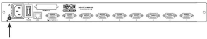
5. Installation (suite)
5. Installation (suite)
5. Installation (suite)
Compose Panel (Panneau composer)
7. Administration (suite)
7. Administration (suite)
7. Administration (suite)
7. Administration (suite)
7. Administration (suite)
7. Administration (suite)
Plage principale de client AP
7. Administration (suite)
7.2.4 Connexions
7. Administration (suite)
7. Administration (suite)


Filtre
7. Administration (suite)
7.2.5 Favoris
7. Administration (suite)
7. Administration (suite)
7.2.8 Accès
7. Administration (suite)
7.2.9 Configuration du port
7. Administration (suite)

7. Administration (suite)
Champ Description
7. Administration (suite)
7. Administration (suite)
7. Administration (suite)
7.2.14 Réseau
7. Administration (suite)
Paramètres RADIUS
7. Administration (suite)
7. Administration (suite)
7. Administration (suite)
7. Administration (suite)
Serveur OpenLDAP
7. Administration (suite)
dn: de=tripalite, de=con
object class top
objectClass doObject
objectClass organization
dn: cn=Manager, dc=triplice, de=com
objectclass top
obje oclia: person
objectclass: organizational person
cn: Manager
sn Manager
obiectcleas: organizational Unit
ou: Users
dn: cn=store,ou=Users,dc=trippite,dc=com
objectclass top
objectclass person
obje etclass organization of person
objectclass: User
cm: 87476
sm Steve
emission w. v. o. c.
UserPassword:
or [ ]sens
cn en=juéyl, ou=Users, de=triplate, de=com
objectclass top
objectclass person
objectclass organizationalPerson
objectless User
cm: jadzyl
go, anded
usePasswordpassword
dn: cn=acc, dc=tripalito, dc=com
objectClass groupOfNames
cn cre
member: cn=justyl, cn=users, dc=triplate, dc=com
in cn-bbb, de-trippite, de-com
objectClass: groupOfNames
cn:bbk
member cn=cc, dc=topplate, dc=com
cn: cn=asa, dc=tripposite, dc=com
objectClass: groupOfName
(四) 50%
member cn=bbb, dc=tripplate, dc=com
access to cn. children="ou=Users, dc=tripposite, dc=com"
by: dn="cr=Manager.de=insplits.de=com" write
by selfread
by spontaneous auth
by+ none

The image contains no legible text or symbols. According to Rule 4 (Edge Noise Strategy), since the ground truth is not clearly visible, the OCR should output nothing.
Therefore, the corrected OCR text is:
```text [No text detected]
database.bdb
cuffig "dc=triplate, dc=com"
toctdo "cn-Monakes de-tripolite, dc-com"
voclow secret
directory /data
7. Administration (suite)
7.2.16 Sécurité
Échecs de connexion
7. Administration (suite)
Chaîne de connexion
7. Administration (suite)
7. Administration (suite)
7. Administration (suite)
7.2.18 Journal
7. Administration (suite)
7.2.19 Entretien
Sauvegarde
7. Administration (suite)
Hôte Ping
7. Administration (suite)
7.3 Log Server
7. Administration (suite)
Événements
7. Administration (suite)
Le List Panel

1111 W. 35th Street, Chicago, IL 60609 USA • tripplite.com/support


- Console KVM Switch with IP Access
- WARRANTY REGISTRATION
- Table of Contents
- FCC Information 3
- User Notice 3
- Package Contents 3
- Introduction 3
- Installation 7
- KVM Operation 12
- Logging Into the KVM over IP 16
- Remote Session Operation 19
- Administration 27
- OSD Operation 32
- Log Server 59
- Specifications 62
- Warranty and Product Registration 64
- FCC Information
- User Notice
- Package Contents
- Introduction
- Overview
- Introduction (continued)
- Features
- System Requirements
- Optional External Console 4.3.3 Remote Console
- Computers
- Supported Browsers
- Cables
- Operating Systems
- Components
- Front View
- Rear View
- Installation
- General Safety Instructions
- Rack Mounting Safety Instructions
- CAUTION!
- Installation (continued)
- Standard Rack Mounting
- Standard Rack Mounting
- Grounding
- LCD OSD Configuration
- 2-Post Rack Mounting
- Single-Station Installation
- Multiple Station (Daisy-Chained) Installation
- To set up a daisy-chained installation:
- Network Setup-IP Address Configuration
- Local Console
- IP Installer
- Browser/Non-Browser Client
- Changing the Super Administrator Login
- KVM Operation
- Sharing USB Peripheral Devices
- Powering Off and Restarting
- Local Console Login
- KVM Operation (continued)
- Local Console Port Access
- Local Console OSD Invocation Sequence
- Local Console OSD Navigation
- Local Console OSD F1 GOTO Function
- Local Console OSD F5 Skip Function
- Local Console OSD F6 Broadcast Mode (BRC)
- Local Console OSD F7 Auto Scan Function
- Local Console OSD F8 Logout Function
- Local Console Pushbuttons
- Local Console Hotkey Commands
- Port Control Hotkeys
- Other Hotkeys
- Invoking the Hotkey Mode
- Num Lock and Minus (-) keys
- Control and F12 keys
- When Hotkey Mode has been invoked:
- Port ID Numbering
- Selecting the Active Port
- Auto Scan Mode
- Skip Mode
- Note:
- Hotkey Beeper Control
- Computer Keyboard/Mouse Reset
- Hotkey Mode Invocation Sequence
- OSD Invocation Sequence
- Port OS Control
- Restore Default Values
- Hotkey Summary Table
- Logging Into the KVM over IP
- Browser Login
- AP Windows Client Login
- Notes:
- The Connection Screen
- The File Menu
- AP Java Client Login
- Remote Session Operation
- Control Panel
- Hotkeys
- Gamma Adjustment
- Button Function
- User List Panel
- Compose Panel
- Message Display Panel
- Mac and Linux Considerations
- Manual Mouse Synchronization
- Windows 2000:
- Windows XP and later:
- Sun / Linux:
- Mouse Synchronization Procedures
- The OSD Toolbar
- Toolbar Hotkeys
- Panel Array Mode
- Auto Scanning
- Setting the Scan Interval
- Invoking Auto Scan
- Panel Array Toolbar
- Pausing Auto Scan
- Exiting Auto Scan
- Administration
- Administration (continued)
- Local Console OSD
- Local Console OSD F2 LIST Function
- Local Console OSD F3 Settings (SET) Page
- Local Console OSD F4 Administration (ADM) Page
- Local Console Firmware Upgrade
- Firmware Upgrade Recovery
- OSD Operation
- The OSD Main Page
- Web Browser Main Page
- AP Client Main Page
- OSD Tab Bar
- Port Access
- Connections
- Internet Explorer
- Non-Windows Browser
- The Port Selection List
- Port Configuration
- Port Naming
- Scan Scan
- Array Mode Panel Array Mode
- Filter Filter
- Interactive Display Panel
- Device Level
- Port Level
- Favorites
- Adding a Favorite
- Modifying a Favorite
- User Preferences
- Sessions
- Access
- Port Configuration
- Port Property
- Associated Link
- User Management
- Adding User Accounts
- Modifying User Accounts
- Deleting User Accounts
- Device Assignment
- Device Management
- Device Information
- Operating Mode
- Network
- Advanced Network Management Settings
- Event Destination
- Log Server
- Authentication
- RADIUS Settings
- LDAP / LDAPS Authentication and Authorization Settings
- LDAP Configuration — Active Directory
- Install the Windows 2003 Support Tools
- Install the Active Directory Schema Snap-in
- Creating a Start Menu Shortcut Entry
- Extend and Update the Active Directory Schema
- OpenLDAP Server
- OpenLDAP Server Installation
- OpenLDAP Server Configuration
- Starting the OpenLDAP Server
- Customizing the OpenLDAP Schema
- LDAP DIT Design and LDIF File
- DIT Creation
- Using the New Schema
- Security
- Login Failures
- Filtering
- IP Filtering
- To delete an IP filter:
- To modify an IP filter:
- Login String
- MAC Filtering
- To add a MAC filter:
- To delete a MAC filter:
- To modify a MAC filter:
- Account Policy
- Encryption
- Working Mode
- Private Certificate
- Certificate Signing Request
- Date/Time
- Time Zone
- Network Time
- Log
- Log Information
- Maintenance
- The Main Screen
- Upgrade Main Firmware
- Main Firmware Upgrade Recovery
- Backup/Restore
- Backup
- Restore
- Ping Host
- System Operation
- Download
- Log Server
- Menu Bar
- Configure
- Add
- Edit
- Delete
- Events
- Options
- Help
- The Log Server Main Screen
- The List Panel
- Specifications
- Specifications (continued)
- Keyboard Emulation
- Mac Keyboard
- Sun Keyboard
- Warranty and Product Registration
- 1-YEAR LIMITED WARRANTY
- PRODUCT REGISTRATION
- Regulatory Compliance Identification Numbers
- WEEE Compliance Information for Tripp Lite Customers and Recyclers (European Union)
- Warning
- Installation (suite)
- Compose Panel (Panneau composer)
- Administration (suite)
- Plage principale de client AP
- Connexions
- Filtre
- Favoris
- Accès
- Configuration du port
- Réseau
- Paramètres RADIUS
- Serveur OpenLDAP
- Sécurité
- Échecs de connexion
- Chaîne de connexion
- Journal
- Entretien
- Sauvegarde
- Hôte Ping
- Événements
- Le List Panel
Brand : Tripp Lite
Model : B020U0819IP
Category : Switch