
NPOEI90W1G - PoE Injector Tripp Lite - Free user manual and instructions
Find the device manual for free NPOEI90W1G Tripp Lite in PDF.

| Product Type | Industrial Gigabit PoE Injector, compliant with IEEE 802.3bt (PoE++) |
| Model | NPOEI90W1G (also includes NPOEI60W1G) |
| Brand | Tripp Lite |
| Dimensions (L x W x H) | 2.4 x 10.9 x 7.4 cm (0.9 x 4.3 x 2.9 in) |
| Weight | 385 g (0.85 lb) |
| Housing Material | Metal, IP30 rating |
| Input Power | Dual input 24-57 V DC via terminal block, up to 4 A DC |
| PoE Output Voltage | 48-57 V DC, 960 mA per pair |
| Maximum PoE Power | 90 W (total budget) |
| RJ45 Ports | 2 ports: 1 input 10/100/1000Base-T, 1 PoE++ output (RJ45) |
| Supported PoE Modes | Mode A, Mode B, 4-pair; support for classes 1 to 8 |
| Diagnostic Features | LEDs: PWR, RPS, ALM, PoE, NBT, PoE Usage (15/30/60/90 W) |
| Configurable DIP Switches | PWR (main alarm), RPS (redundant alarm), NBT (legacy/standard) |
| Operating Temperature Range | -40 to 75 °C |
| Operating Humidity Range | 5 to 95% RH non-condensing |
| Mounting | DIN rail (included) or wall-mount (optional) |
| Safety and Compliance Standards | IEEE 802.3af/at/bt, RoHS 3, FCC, IEC 61000-4-2/3/4/5/6/8, EN 60068-2-6/27/32 |
| Warranty | 3-year limited warranty |
| Package Contents | PoE injector, DIN rail kit, quick start guide |
| Typical Applications | IP cameras, VoIP phones, outdoor kiosks, PoE LED lighting, Wi-Fi 6 access points |
| Cooling | Passive (fanless) |
Frequently Asked Questions - NPOEI90W1G Tripp Lite
User questions about NPOEI90W1G Tripp Lite
0 question about this device. Answer the ones you know or ask your own.
Ask a new question about this device
Download the instructions for your PoE Injector in PDF format for free! Find your manual NPOEI90W1G - Tripp Lite and take your electronic device back in hand. On this page are published all the documents necessary for the use of your device. NPOEI90W1G by Tripp Lite.
USER MANUAL NPOEI90W1G Tripp Lite
Register your product today and be automatically entered to win an ISOBAR ^® surge protector in our monthly drawing!
tripplite.com/warranty


Manufacturing Excellence.
1111 W. 35th Street, Chicago, IL 60609 USA • tripplite.com/support
Copyright © 2021 Tripp Lite. All rights reserved.
Product Features
- Deliver power and data up to 328 ft. (100 m) through existing cabling
- Extend power and data to any PoE or PoE+ device installed where no AC outlet is available
- Support Gigabit Ethernet data transfer speeds up to 1000 Mbps (1 Gbps)
- Maximum output of 57V can compensate for voltage drop on long cable runs
- PD detection function determines whether devices connected to the system are compatible
- Compact, hand-sized metal housings ready for mounting on any DIN rail
- Plug-and-play operation with no configuration required for easy, immediate installation
Package Contents
• NPOEI-60W-1G or NPOEI-90W-1G PoE Injector
- DIN Rail Kit
- Quick Start Guide
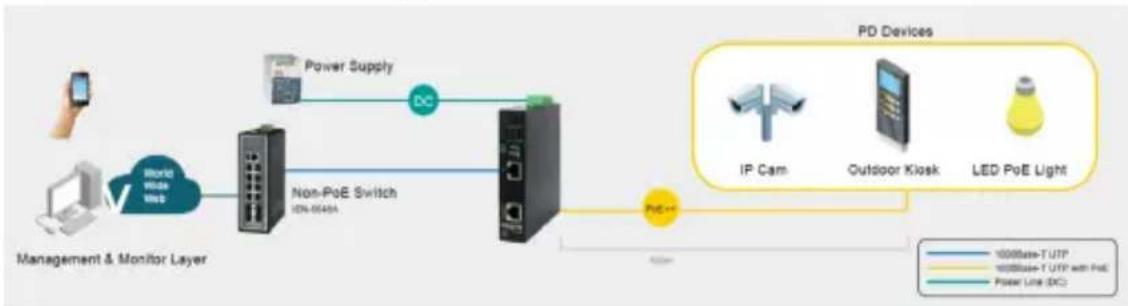
Applications
The PoE Injectors provide power up to 60W (NPOEI-60W-1G) or 90W (NPOEI-90W-1G) to use power more efficiently on PoE devices, including surveillance cameras, VoIP phones, outdoor kiosks and smart PoE lights.
flowchart
graph LR
    A["Management & Monitor Layer"] --> B["Non-PoE Switch"]
    B --> C["Power Supply"]
    C --> D["PC"]
    D --> E["PD Devices"]
    E --> F["IP Cam"]
    E --> G["Outdoor Kiosk"]
    E --> H["LED PoE Light"]
    style A fill:#f9f,stroke:#333
    style B fill:#ccf,stroke:#333
    style C fill:#cfc,stroke:#333
    style D fill:#fcc,stroke:#333
    style E fill:#cff,stroke:#333
    style F fill:#ffc,stroke:#333
    style G fill:#ffc,stroke:#333
    style H fill:#ffc,stroke:#333
Notes:
- NPOEI-60W-1G is recommended for Wi-Fi applications that require more than 30W of power.
- NPOEI-90W-1G is recommended for outdoor applications to supply power to LED lights, 360° cameras and heater elements.
Mounting and Dismounting Instructions
Notes:
- These open-type devices shall be DIN-rail mounted or wall mounted (optional) in a cabinet or enclosure where the ambient temperature shall not exceed 75°C.
- Caution: Hot surface! Do not touch. Please wear protective equipment before coming into contact.
- A corrosion-free mounting rail is advisable. When installing, allow enough space between devices to properly install cabling and provide room for proper airflow.
To mount, place the PoE injector on the DIN rail using the slot. Push the front of the unit toward the mounting surface until it snaps into place with a “click” sound.
To dismount, press the unit from the top, and pull out the lower edge of it. Remove the unit from the DIN rail.
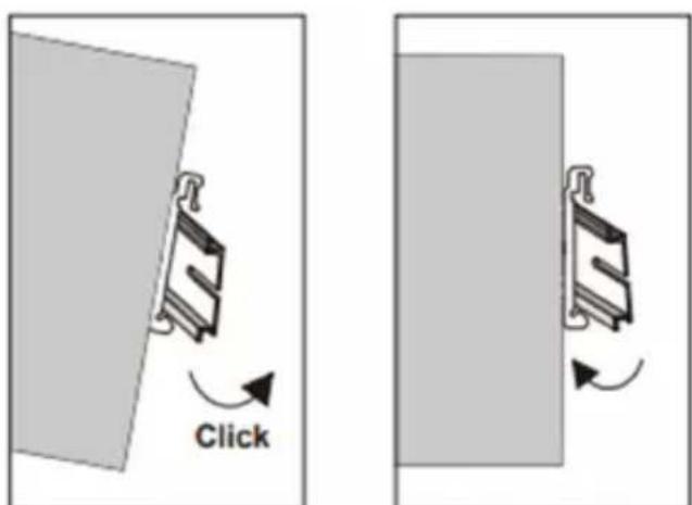
Mounting the Injector Removing the Injector
Grounding the PoE Injector
Note: These PoE injectors are intended to be mounted to a well-grounded mounting surface, such as a metal panel.
Grounding and wire routing help limit the effects of line noise due to electromagnetic interferences (EMI). Run the ground connection from the ground screw to the grounding surface before connecting.
Wiring Requirements
Note: Safety measures should be taken before connecting the power cable. Please turn off the power before connecting any modules or wires. The correct power supply voltage is listed on the product label. Check the voltage of your power source to make sure you are using the correct voltage. DO NOT use a voltage greater than what is specified on the product label. If the current exceeds the maximum rating, the wiring can overheat and cause serious damage to your equipment.
- Use separate paths to route wiring for power and devices. If the power wiring and device wiring paths must cross, make sure the wires are perpendicular at the intersection point.
Note: Do not run signal or communications wiring and power wiring through the same wire conduit. To avoid interference, wires with different signal characteristics should be routed separately. - You can use the type of signal transmitted through a wire to determine which wires should be kept separate. The rule of thumb is that wiring that shares similar characteristics can be bundled together.
- You should separate input wiring from output wiring.
- It is recommended that you label the wiring to all system devices.
Wiring Requirements
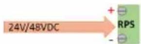
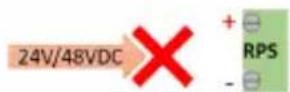
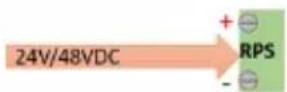
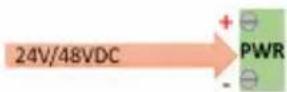
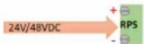
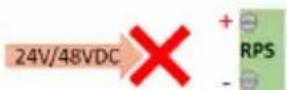
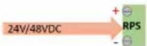
Wiring Power Input
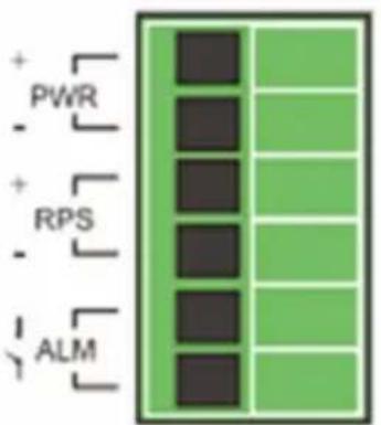
Terminal Block

24\~57VDC
You can use “Terminal Block (PWR)” for Primary Power Input and “Terminal Block (RPS)” for secondary power source for Redundant Power Input.
Caution:
• Use copper conductors only
- Wiring cable temperature should support at least 105^ C
- Tighten the wire to a torque value of 4.5 lb./in.
- Wire gauge for the terminal block should range between 14 AWG and 20 AWG
Wiring Requirements
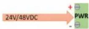
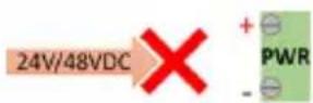
Connecting to Terminal Block
To insert power wire and connect the 24-57VDC at a maximum of 4A DC power to the power terminal block, please follow the steps below:
- Use a flat-head screwdriver to loosen the wire-clamp screws.
- Insert the negative/positive DC wires into the PWR-/PWR+ terminals.
- Tighten the wire-clamp screws to prevent the wires from loosening.
Wiring Requirements
Wiring the Relay Contact (ALM)
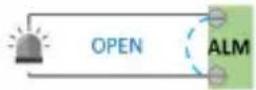
The NPOEI-60W-1G and NPOEI-90W-1G have one set of relay alarm outputs. This relay contact uses two contacts of the terminal block on the top panel of the unit. The two contacts of the 6-pin terminal block connector are used to detect user-configured events. The two wires attached to the fault contacts form an open circuit when a user-configured event occurs. If a user-configured event does not occur, the fault circuit will remain closed. Therefore, in the event of a power loss by main power or aux power or system overload, an external signal can be detected.
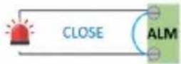
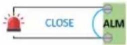
See the chart below:
ALM LED
In normal case

If RPS of DIP Switch is ON

If PWR of DIP Switch is ON

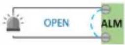
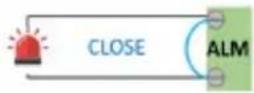
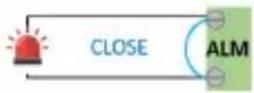

for system overloading
Wiring Requirements
RJ45 Cabling
Connect one end of a user-supplied RJ45 cable to an Ethernet port and the other end to the PoE Injector.
Note: Cat5e cable or above is recommended for best results.
DIP Switch Settings
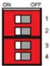
| PWR ON | Primary power | alarm reporting enabled |
| OFF Primary power alarm reporting disabled | ||
| RPS ON | Redundant power alarm reporting enabled | |
| OFF Redundant power alarm reporting disabled | ||
| NBT ON | Legacy mode enabled; 2-pair detection support | |
| OFF 802.3bt Standard mode enabled; 4-pair detection support | ||
| RSV | Reserved | |
Specifications
| General Specifications | ||
| Product Name | NPOEI-60W-1G NPOEI-90W-1G | |
| Product Type | PoE Injector PoE Injector | |
| Housing | Metal Metal | |
| Housing Rating | IP-30 IP-30 | |
| Weight | 0.85 lb. (385 g) 0.85 lb. (385 g) | |
| Dimensions | 1 x 4.6 x 4 in.(2.5 x 11.6 x 10 cm) | 0.9 x 4.3 x 2.9 in.(2.4 x 10.9 x 7.4 cm) |
| Port 1 | 10/100/1000Base-T RJ45 10/100/1000Base-T RJ45 | |
| Port 2 | 10/100/1000Base-T 60W PoE++ | 10/100/1000Base-T 90W PoE++ |
| Operating Temperature Range | -40° to 75°C -40° to 75°C | |
| Operating Humidity Range | 5 to 95% RH, Non-Condensing 5 to 95% RH, Non-Condensing | |
| Storage Temperature Range | -40° to 85°C -40° to 85°C | |
| Storage Humidity Range | 5 to 95% RH, Non-Condensing 5 to 95% RH, Non-Condensing | |
| MTBF Calculated @ 25 | 645,827 hours 645,827 hours | |
| MTBF Calculated @ 75 | 81,636 hours 81,636 hours | |
| LED Panel | PWR, RPS, ALM, PoE, NBT,63~66W PoE Usage(15, 30, 60) | PWR, RPS, ALM, PoE, NBT,93~96W PoE Usage(15, 30, 60, 90) |
| Cooling Fan | N/A N/A | |
| DIP Switch Settings | PWR, RPS, NBT, RSV PWR, RPS, NBT, RSV | |
| Electrical Specifications | ||
| Max PoE Budget | 60W 90W | |
| Input Power | Dual 24 ~ 57 VDC,Terminal Block | Dual 24 ~ 57 VDC,Terminal Block |
| Output Voltage | 48 – 57 VDC 48 – 57 VDC | |
| Max Current | 600 ma/pair | 960 ma/pair |
| Supported Modes | Mode A, Mode B, 4-Pair Mode | 4-Pair Mode Mandatory |
| Power Management | 6 power class levels (1-6) | 8 power class levels (1-8) |
Specifications
| Specification Conformance | ||
| Normal Specification IEEE 802.3af (Type1),802.3at (Type 2),802.3bt (Type 3) | IEEE 802.3af (Type1),802.3at, 802.3btType 3, 4) | |
| MDI/MDX Yes Yes | ||
| Plug and Play Yes Yes | ||
| PD Detection Function Yes Yes | ||
| Overload Protection Yes Yes | ||
| Meets RoHS 3 Specifications Yes Yes | ||
| Meets FCC Requirements Yes Yes | ||
| Vibration Specification EN 60068-2-6 | EN 60068-2-6 | |
| Shock Specification EN-60068-2-27 | EN 60068-2-27 | |
| Free Fall Specification EN 60068-2-3 | 2 EN 60068-2-32 | |
| Meets IEC 61000-4-2 (ESD) Yes, Air | 15KV /Contact 8KV | Yes, Air 15KV /Contact 8KV |
| Meets IEC 61000-4-3 (RS) | Yes Yes | |
| Meets IEC 61000-4-4 (EFT) Yes Yes | ||
| Meets IEC 61000-4-5 (Surge) | Yes Yes | |
| Meets IEC 61000-4-6 (CS) | Yes Yes | |
| Meets IEC 61000-4-8 (PFMF) Yes Yes | ||
| Supports Cisco UPoE Standard | Yes Yes | |
| Supports Type 1 Devices (15.4W) | Yes Yes | |
| Supports Type 2 Devices (30W) | Yes Yes | |
| Supports Type 3 Devices (60W) | Yes Yes | |
| Supports Type 4 Devices (90W) | No Yes | |
| Supports 802.11ax Wi-Fi 6 | Yes Yes | |
| Supports IEEE 802.bt IPCameras from Bosh and Axis | Yes Yes | |
LED Indicators
| NPOEI-60W-1G | ||
| PWR(Green) | Illuminated Primary Power on | |
| Off Primary Power off or failure | ||
| RPS(Green) | Illuminated Redundant Power on | |
| Off Redundant Power off or failure | ||
| ALM(Red) | Illuminated Alarm for following conditions (when DIP switches are turned on):Primary Power lostSecondary Power lostPoE overload | |
| Off Normal operation | ||
| PoE(Green) | Illuminated PoE in use & <15W if w/o illumination of PoE Usage LEDs | |
| Off No PoE in use | ||
| NBT(Green) | Illuminated 2-pair detection mode enabled | |
| Off Default 4-pair detection mode enabled | ||
| 63~66W(Red) | Blinking Overload (>=63W, <=66W) | |
| Off No power delivery or <63W or >66W of PoE max loading (PoE power cutting) | ||
| PoE Usage(Green) | 15 Injector provides PoE power range 15W~<30W | |
| 30 Injector provides PoE power range 30W~<60W | ||
| 60 Injector provides PoE power range >60W | ||
LED Indicators
| NPOEI-90W-1G | ||
| PWR(Green) | Illuminated Primary Power on | |
| Off Primary Power off or failure | ||
| RPS(Green) | Illuminated Redundant Power on | |
| Off Redundant Power off or failure | ||
| ALM(Red) | Illuminated Alarm for following conditions (when DIP switches are turned on):Primary Power lostSecondary Power lostPoE overload | |
| Off Normal operation | ||
| PoE(Green) | Illuminated PoE in use & <15W if w/o illumination of PoE Usage LEDs | |
| Off No PoE in use | ||
| NBT(Green) | Illuminated 2-pair detection mode enabled | |
| Off Default 4-pair detection mode enabled | ||
| 93~96W(Red) | Blinking Overload (>=93W, <=96W) | |
| Off No power delivery or <93W or >96W of PoE max loading (PoE power cutting) | ||
| PoE Usage(Green) | 15 Injector provides PoE power range 15W~<30W | |
| 30 Injector provides PoE power range 30W~<60W | ||
| 60 Injector provides PoE power range 60W~<90W | ||
| 90 Injector provides PoE power range >90W | ||
Warranty and Product Registration
3-Year Limited Warranty
Seller warrants this product, if used in accordance with all applicable instructions, to be free from original defects in material and workmanship for a period of three (3) years from the date of initial purchase. If the product should prove defective in material or workmanship within that period, Seller will repair or replace the product, at its sole discretion.
THIS WARRANTY DOES NOT APPLY TO NORMAL WEAR OR TO DAMAGE RESULTING FROM ACCIDENT, MISUSE, ABUSE OR NEGLECT. SELLER MAKES NO EXPRESS WARRANTIES OTHER THAN THE WARRANTY EXPRESSLY SET FORTH HEREIN. EXCEPT TO THE EXTENT PROHIBITED BY APPLICABLE LAW, ALL IMPLIED WARRANTIES, INCLUDING ALL WARRANTIES OF MERCHANTABILITY OR FITNESS, ARE LIMITED IN DURATION TO THE WARRANTY PERIOD SET FORTH ABOVE; AND THIS WARRANTY EXPRESSLY EXCLUDES ALL INCIDENTAL AND CONSEQUENTIAL DAMAGES. (Some states do not allow limitations on how long an implied warranty lasts, and some states do not allow the exclusion or limitation of incidental or consequential damages, so the above limitations or exclusions may not apply to you. This warranty gives you specific legal rights, and you may have other rights which vary from jurisdiction to jurisdiction.)
WARNING: The individual user should take care to determine prior to use whether this device is suitable, adequate or safe for the use intended. Since individual applications are subject to great variation, the manufacturer makes no representation or warranty as to the suitability or fitness of these devices for any specific application.
PRODUCT REGISTRATION
Visit tripplite.com/warranty today to register your new Tripp Lite product. You'll be automatically entered into a drawing for a chance to win a FREE Tripp Lite product!*
*No purchase necessary. Void where prohibited. Some restrictions apply. See website for details.
WEEE Compliance Information for Tripp Lite Customers and Recyclers (European Union)

Under the Waste Electrical and Electronic Equipment (WEEE) Directive and implementing regulations, when customers buy new electrical and electronic equipment from Tripp Lite, they are entitled to:
- Send old equipment for recycling on a one-for-one, like-for-like basis (this varies depending on the country)
- Send the new equipment back for recycling when this ultimately becomes waste
Use of this equipment in life support applications where failure of this equipment can reasonably be expected to cause the failure of the life support equipment or to significantly affect its safety or effectiveness is not recommended.
Tripp Lite has a policy of continuous improvement. Specifications are subject to change without notice. Photos and illustrations may differ slightly from actual products.


1111 W. 35th Street, Chicago, IL 60609 USA • tripplite.com/support
16
21-04-051 · 93-3E83_RevA

24\~57VDC
If RPS of DIP Switch is ON
If PWR of DIP Switch is ON


1111 W. 35th Street, Chicago, IL 60609 EE UU • tripplite.com/support
32
21-04-051 · 93-3E83_RevA
1111 W. 35th Street, Chicago, IL 60609 USA • tripplite.com/support

24\~57VDC
If RPS of DIP Switch is ON
If PWR of DIP Switch is ON


1111 W. 35th Street, Chicago, IL 60609 USA • tripplite.com/support
48
21-04-051 · 93-3E83_RevA
- Product Features
- Package Contents
- Applications
- Notes:
- Mounting and Dismounting Instructions
- Grounding the PoE Injector
- Wiring Requirements
- Wiring Power Input
- Caution:
- Connecting to Terminal Block
- Wiring the Relay Contact (ALM)
- ALM LED
- RJ45 Cabling
- DIP Switch Settings
- LED Indicators
- Warranty and Product Registration
- 3-Year Limited Warranty
- PRODUCT REGISTRATION
- WEEE Compliance Information for Tripp Lite Customers and Recyclers (European Union)
Brand : Tripp Lite
Model : NPOEI90W1G
Category : PoE Injector