Energion Nuos Plus 250 - Boiler Atag - Free user manual and instructions
Find the device manual for free Energion Nuos Plus 250 Atag in PDF.
| Product type | Thermodynamic boiler (heat pump + electric resistance) |
| Brand | Atag |
| Model | Energion Nuos Plus 250 |
| Nominal tank capacity | 250 L |
| Height | 1997 mm |
| Width / Diameter | 680 mm |
| Depth | 680 mm |
| Empty weight | 95 kg |
| Electrical power supply | 220-240 V ~ 50 Hz, single-phase |
| Maximum electrical power consumption (heat pump) | 900 W |
| Electric resistance power | See rating plate (up to 1,500 W) |
| Maximum water temperature (resistance) | 75 °C |
| Maximum water temperature (heat pump) | 62 °C |
| COP (according to EN 16147) | 3.35 |
| Load profile | XL |
| Refrigerant fluid | R134a (1.3 kg) |
| Global warming potential (GWP) | 1,430 (CO2 eq. 1.859 t) |
| Maximum working pressure (tank) | 0.6 MPa (6 bar) |
| Tank protection | Enameled + impressed current titanium anode + magnesium anode |
| Protection index | IPX4 |
| Operating modes | Green, Comfort, Fast, Auto (I-Memory), HC-HP (off-peak hours), Boost, Holiday |
| Special functions | Antibacterial (legionella), Silent, Frost protection, PV (photovoltaic), SG (Smart Grid) |
| Time program | 4 time slots per day, customizable per day |
| Periodic maintenance | Annual cleaning of evaporator filter; monthly inspection of safety group |
| Draining | Essential in case of frost risk; detailed procedure in the manual |
| Certifications | CE, NFC 15-100, EN 16147, REACH, WEEE |
Frequently Asked Questions - Energion Nuos Plus 250 Atag
User questions about Energion Nuos Plus 250 Atag
0 question about this device. Answer the ones you know or ask your own.
Ask a new question about this device
Download the instructions for your Boiler in PDF format for free! Find your manual Energion Nuos Plus 250 - Atag and take your electronic device back in hand. On this page are published all the documents necessary for the use of your device. Energion Nuos Plus 250 by Atag.
USER MANUAL Energion Nuos Plus 250 Atag
natural_image
Line drawing of a rectangular industrial machine with mounting holes and control panel (no text or symbols)200 - 250 250 SYS - 250 TWIN SYS
CONSIGNES GÉNÉRALES DE SÉCURITÉ
text_image
A C M B D N L E I G H F CEtext_image
Technical diagram of a mechanical device with numbered components for identificationtext_image
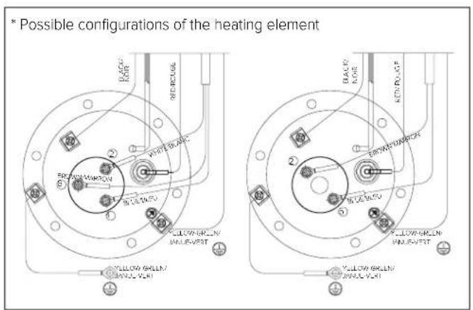
Electrical wiring diagram with labeled components and connections, including color-coded wires, connectors, and indicator lights.FONCTION ANTI-LÉGIONELLE
text_image
AUX BUS SG2 SG1 N L A NRACCORDEMENT ELECTRIQUE AVEC TARIF BI-HORAIRE ET SIGNAL HC-HP
text_image
AUX BUS SG2 SG1 N L EDF B N LCONNEXION AUXILIAIRE
ATTENTION: signal 230 V.
text_image
AUX SG2 SG1 N L D C A N IS-A• SYSTEM = YES Cascade = YES
text_image
AUX BUS SG2 SG1 N L A BUS 16 A N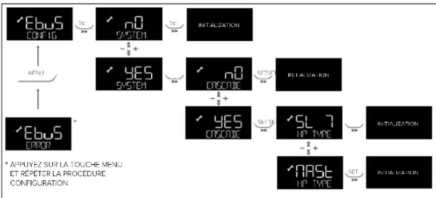
flowchart
graph TD
    A["EBuS CONFIG"] -->|SET >>| B["n0 SYSTEM"]
    B -->|-x +| C["YES SYSTEM"]
    C -->|SET >>| D["n0 CASCADE"]
    D -->|-x +| E["YES CASCADE"]
    E -->|SET SE >>| F["SL 7 HP TYPE"]
    F -->|-x +| G["NASL HP TYPE"]
    G -->|SET >>| H["INITIALIZATION"]
    I["MENU"] --> J["EBuS ERROR"]
    J --> K["* APPUYEZ SUR LA TOUCHE MENU ET REPETER LA PROCEDURE CONFIGURATION"]
TYPOLOGIES D'INSTALLATION AVEC D'AUTRES GÉNÉRATEURS THERMIQUES
natural_image
Pure electrical circuit lines without any symbols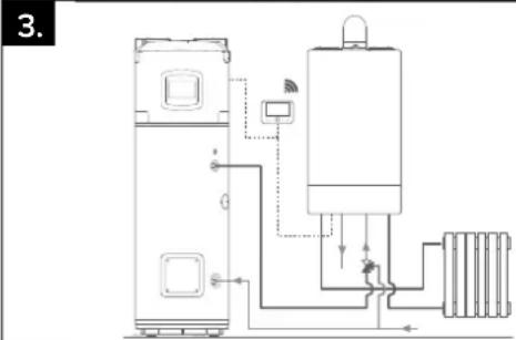
natural_image
Technical line drawing of a mechanical or electrical device with no visible text, numbers, or symbols.MISE EN SERVICE

ATTENTION!
DOUCHES DISPONIBLE "
[START1] = 8:00; [STOP1] = 12:00;
[START2] = 16:00; [STOP2] = 20:00;
[START3] = 00:00; [STOP3] = 00:00;
[START4] = 00:00; [STOP4] = 00:00;
natural_image
Industrial machine with transparent sheet metal components and a worker operating it (no visible text or symbols)
natural_image
Close-up of a hand holding a flat object over a surface, possibly a tool or device (no visible text or symbols)GENERAL SAFETY INSTRUCTIONS
-
Read the instructions and warning in this manual carefully, they contain important information regarding safe installation, use and maintenance. This manual is an integral part of the product. Hand it on to the next user/owner in case of change of property.
-
The manufacturer shall not liable for any injury to people, animals or damage to property caused by improper, incorrect or unreasonable use or failure to follow the instructions reported in this publication.
-
Installation and maintenance must be performed by professionally qualified personnel as specified in the relative paragraphs. Only use original spare parts. Failure to observe the above instructions can compromise the safety of the appliance and relieves the manufacturer of any liability for the consequences.
-
DO NOT leave the packaging materials (staples, plastic bags, expanded polystyrene, etc.) within the reach of children they can cause serious injury.
-
The appliance may not be used by persons under 8 years of age, with reduced physical, sensory or mental capacity, or lacking the requisite experience and familiarity, unless under supervision or following instruction in the safe use of the appliance and the hazards attendant on such use. DO NOT permit children to play with the appliance. User cleaning and maintenance may not be done by unsupervised children.
-
DO NOT touch the appliance when barefoot or if any part of your body is wet.
-
Before using the device and after routine or extraordinary maintenance, we recommend filling the appliance's tank with water and draining it completely to remove any residual impurities.
-
If the appliance is equipped with a power cord, the latter may only be replaced by an authorised service centre or professional technician.
-
It is mandatory to screw o the water inlet pipe of the unit a safety valve in accordance with national regulations. In countries which have enacted EN 1487, the safety group must be calibrated to a maximum pressure of 0,7 MPa and include at least a cock, check valve and control, safety valve and hydraulic load cut-out.
-
Do not tamper with the overpressure safety device (valve or safety group), if supplied together with the appliance; trip it from time to time to ensure that it is not jammed and to remove any scale deposits.
-
It is normal water drips from the overpressure safety device when the appliance is heating. For this reason, the drain must be connected, always left open to the atmosphere, with a drainage pipe installed in a continuous downward slope and in a place free of ice.
-
Make sure you drain the appliance and disconnect it from the power grid when it is out of service in an area subject to subzero temperatures.
-
Water heated to over 50 °C can cause immediate serious burns if delivered directly to the taps. Children, disabled persons and the aged are particularly at risk. We recommend installing a thermostatic mixer valve on the water delivery line, marked with a red collar.
-
Do not leave fl ammable materials in contact with or in the vicinity of the appliance.
-
Do not place anything under the water heater which may be damaged by a leak..
-
The water heating heat pump is supplied with a sufficient amount of R134a or R513a refrigerant for its operation. This refrigerant fluid does not damage the atmosphere's ozone layer, is not flammable and does not cause explosions; however any maintenance activities or work on the refrigerant circuit must only be carried out by authorised personnel and with the use of suitable equipment.
SAFETY REGULATIONS
Key to symbols:
Failure to comply with this warning implies the risk of personal injury, in some circumstances even fatal.
Failure to comply with this warning may result in serious damage to property, plants or animals. The manufacturer is not liable for damage resulting from improper use of the product or failure to install it as instructed herein.
Install the appliance on a solid basement which is not subject to vibration.
△ Noisiness during operation.
When drilling holes in the wall for installation purposes, take care not to damage any electrical wiring or existing piping.
Electrocution caused by contact with live wires. Damage to existing installations.
Flooding caused by water leaking from damaged pipes.
Perform all electrical connections using wires which have a suitable section. The connection product must be carried out following the instructions provided in the relative paragraph.
⚠️ Fire caused by overheating due to electrical current passing through undersized cables.
Protect all connection pipes and wires in order to prevent them from being damaged.
Electrocution caused by contact with live wires. Flooding caused by water leaking from damaged piping.
Make sure the installation site and any systems to which the appliance must be connected comply with the applicable norms in force.
Electrocution caused by contact with live wires which have been installed incorrectly.
△ Damage to the appliance caused by improper operating conditions.
Use manual tools and equipment that are suitable for the intended use (in particular, ensure that the tool is not worn and that the handle is intact and securely fixed); use them correctly and prevent them falling from a height. Put them safely back in place after use.
Personal injury caused by flying splinters or fragments, inhalation of dust, knocks, cuts, puncture wounds and abrasions.
△ Damage to the appliance or surrounding objects caused by falling splinters, knocks and incisions.
Use electrical equipment that is suitable for the intended use; use the equipment correctly, keep passages clear of the power supply cable, prevent the equipment falling from a height, disconnect and put back in place after use.
Personal injury caused by flying splinters or fragments, inhalation of dust, knocks, cuts, puncture wounds and abrasions.
△ Damage to the appliance or surrounding objects caused by falling splinters, knocks and incisions.
Make sure that any portable ladders are securely positioned, that they are sufficiently resistant, that the steps are intact and not slippery, that these do not move around when someone climbs on them and that someone supervises at all times.
Personal injury caused by falling from a height or cuts (stepladders shutting accidentally).
Make sure that the work area has adequate hygiene and health conditions in terms of lighting, ventilation and the solidity of relevant structures.
Personal injury caused by knocks, stumbling etc.
Protect the appliance and all areas in the vicinity of the work place using suitable material.
△ Damage to the appliance or surrounding objects caused by falling splinters, knocks and incisions.
Handle the appliance with suitable protection and with care..
△ Damage to the appliance or surrounding objects from shocks, knocks, incisions and squashing.
During all work procedures, wear individual protective clothing and equipment. It is forbidden to touch the product installed, without shoes or with parts of the body are weti.
△ Personal injury caused by electrocution, falling splinters or fragments, inhalation of dust, shocks, cuts, puncture wounds, abrasions, noise and vibration.
Reset all safety and control functions affected by any work performed on the appliance and make sure that they operate correctly before restarting the appliance.
△ Damage or shutdown of the appliance caused by out-of-control operation.
Before handling, empty all components that may contain hot water, carrying out any bleeding if necessary.
⚠️ Necessary. Personal injury caused by burns.
Descale the components, in accordance with the instructions of the safety data sheet included with the product used, while ventilating the room and wearing protective clothing; avoid mixing different products and protect the appliance and surrounding objects.
Personal injury caused by acidic substances coming into contact with skin or eyes; inhaling or swallowing harmful chemical agents.
△ Damage to the appliance or surrounding objects due to corrosion caused by acidic substances.
Instructions and technical norms
The purchaser pays for the appliance's installation, which must be carried out by qualified personnel only, in conformity with national regulations in force and any provisions emitted by local authorities or bodies responsible for public health, and in accordance with the specific manufacturer indications contained in this manual. The manufacturer is responsible for the product's conformity to the relevant construction directives, laws and regulations in force at the time the product is first commercialised. The designer, installer and user are each exclusively responsible, in their respective fields, for knowing and observing the legal requirements and technical regulations concerning the design, installation, operation and maintenance of the appliance.
Any reference to laws, regulations or technical specifications contained in this manual is purely for information purposes; any new laws introduced or modifications to existing laws are not in any way binding on the manufacturer towards third parties. It is necessary to ensure that the power supply network to which the product is connected complies with the EN 50160 norm (under penalty of warranty invalidation). Relative to France, ensure that installation complies with the NFC 15-100 norm. The tampering of product integral parts and/or supplied accessories invalidates the warranty.
Field of application
This appliance is intended for hot water production for domestic use or similar, at temperatures below boiling point.
The appliance must be hydraulically connected to a domestic water supply line and to a power supply network.
Air ducts may be used for the entry and discharge of processed air.
It is forbidden to use of the appliance for uses other than those specified. Any alternative use of the appliance constitutes improper use and is prohibited; in particular, the appliance may not be used in industrial cycles and/or installed in environments exposed to corrosive or explosive materials. The manufacturer shall not be held liable for any damage due to faulty installation, improper use or uses deriving from behaviour that is not reasonably predictable, and incomplete or careless implementation of the instructions contained in this manual.
Operating principle
The efficiency of a heat pump operation is measured by the Coefficient of Performance (COP), i.e. the ratio between the energy supplied to the appliance (in this case, the heat transferred to the water to be heated) and the electrical energy used (by the compressor and the appliance's auxiliary devices). The COP varies according to the type of heat pump and to its relative conditions of operation.
For example, a COP value equal to 3 indicates that for every 1 kWh of electrical energy used, the heat pump supplies 3 kWh of heat to the medium to be heated, of which 2 kWh are extracted from the free source.
Packaging and supplied accessories
The appliance is anchored to a wooden pallet and is protected with polystyrene top cover, wooden edge protectors, and external cardboard; all the materials are recyclable and eco-compatible.
The following accessories are included:
- Connection pipe for condensation water.
- 2 ^3/4 " dielectrics joints.
- Instruction manual and warranty document.
- Energy label and product fiche.
- 2 adapters for ∅150 and ∅160 ducts.
Product certifications
The CE marking of the appliances attests its conformity to the following EC Directives, of which it satisfies the essential requisites:
- 2014/35/EU on electrical safety LVD (EN/IEC 60335-1; EN/IEC 60335-2-21; EN/IEC 60335-2-40);
- 2014/30/EU on electromagnetic compatibility EMC (EN 55014-1; EN 55014-2; EN 61000-3-2; EN 61000-3-3);
- RoHS3 (2015/863) on restriction of use on certain hazardous substances in electrical and electronic equipment (EN 50581).
- Commission Regulation (UE) n. 814/2013 on ecodesign (n. 2014/C 207/03 - transitional methods of measurement and calculation)
Verification of performance is carried out through the following technical regulations:
- EN 16147;
This product complies with:
- REACH 1907/2006/EC regulation;
- (UE) n. 812/2013 (labelling) regulation
- D.M. 174 del 06/04/2004 implementing European Directive 98/83 on the quality of water.
- Radio Equipment Directive (RED): ETSI 301489-1, ETSI 301489-17.
Identification of the appliance
The main information for identifying the appliance is contained on the adhesive data plate located on the water heater casing.
| A C | ||
| M B D | ||
| N | ||
| L E | ||
| I G | ||
| H F CE | ||
| A Model | ||
| B Tank capacity | ||
| C Serial no. | ||
| D Power supply voltage. frequency. maximum absorbed power | ||
| E Max./min. pressure of the refrigeration circuit | ||
| F Tank protection | ||
| G Absorbed power – heating element mode | ||
| H Marks and symbols | ||
| I Max./min. power in heat pump mode | ||
| L Type of refrigerant and charge | ||
| M Maximum tank pressure | ||
| N global warming potential / Quantity of fluorinated greenhouse gases |
PRODUCT DESCRIPTION
The floor-standing water heating heat pump consists of a top block containing the heat pump unit and the bottom part of the with the storage tank. There is a control panel with a display on the front part.
Dimensions
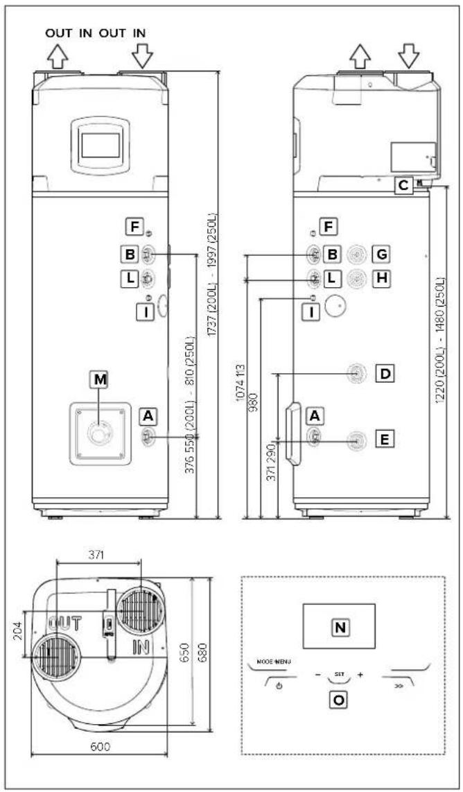
text_image
OUT IN OUT IN F B L I 376 550 (200L) - 810 (250L) 1737 (200L) - 1997 (250L) M A 1074 13 980 371 290 D A E 1220 (200L) - 1480 (250L) 371 204 OUT IN 650 680 600 N NODE MENU φ - SET + >> O| A Inlet cold water 3/4" connection |
| B Outlet hot water 3/4" connection |
| C Condensate drain connection with 14mm diameter |
| D Auxiliary circuit 3/4" inlet pipe (SYS and TWIN) |
| E Auxiliary circuit 3/4" outlet pipe (SYS and TWIN) |
| F Sheath for upper probe (S3) (SYS and TWIN) |
| G Auxiliary circuit 3/4" inlet pipe (TWIN SYS) |
| H Auxiliary circuit 3/4" outlet pipe (TWIN SYS) |
| I Sheath for upper probe (S4) (TWIN SYS) |
| L Recirculation 3/4" pipe (SYS and TWIN SYS) |
| M Sheath for bottom probe (S2) (SYS and TWIN SYS) |
| N Display |
| O Touch buttons. |
Main components
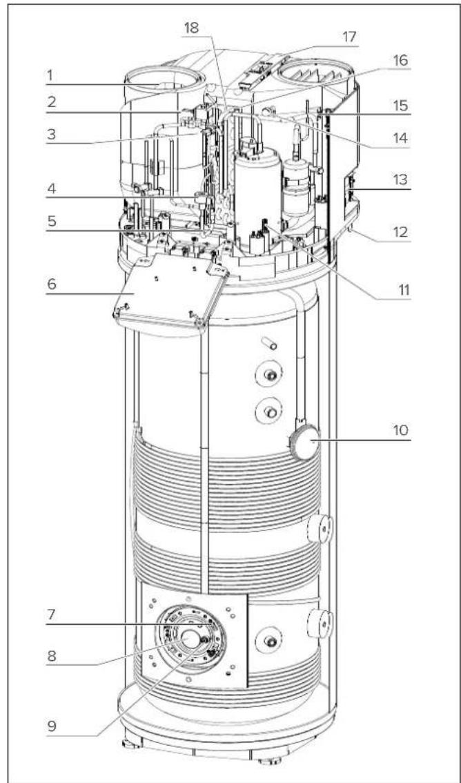
text_image
Technical diagram of a cylindrical mechanical device with numbered components for identification| 1 | Fan |
| 2 | Hot gas valve |
| 3 | Safety pressure switch |
| 4 | Electronic expansion valve |
| 5 | Evaporator inlet NTC temperature probe |
| 6 | Electronic box |
| 7 | Bottom NTC temperature probe (heating element zone) |
| 8 | Electric heating element |
| 9 | Impressed current anode |
| 10 | Top NTC temperature probe (hot water) |
| 11 | Hermetic rotary compressor |
| 12 | Condensate drain pipe |
| 13 | Lateral connections |
| 14 | Low pressure outlet |
| 15 | Air NTC temperature probe |
| 16 | Compressor suction NTC temperature probe |
| 17 | Evaporator filter |
| 18 | Evaporator |
TECHNICAL DATA TABLE
| DESCRIPTION | Unit 200 250 250 SYS | 250 TWIN SYS | |||
| Rated tank capacity | 1 200 250 245 240 | ||||
| Insulation thickness | mm = 50 | ||||
| Type of internal tank protection | Enamelling | ||||
| Type of corrosion protection | Titanium impressed current anode + disposable magnesium anode | ||||
| Maximum operating pressure | MPa 0,6 | ||||
| Diameter of hydraulic connections | II G 3/4 M | ||||
| Diameter of condensate drainage connection | mm 14 | ||||
| Diameter of air exhaust/intake pipes | mm 150-160-200 | ||||
| Minimum water hardness | °F 12 | ||||
| Minimum conductivity of the water | μS/cm 150 | ||||
| Weight when empty | kg 90 95 115 | 130 | |||
| Heating bottom circuit exchange surface | m2 | - | - | 0,65 | 0,65 |
| Heating top circuit exchange surface | m2 | - | - | - | 0,65 |
| Max water temperature with external integration | °C | - | - | 75 | 75 |
| HEAT PUMP | |||||
| Average electrical power consumption | W | 700 | |||
| Max. electrical power consumption | W | 900 | |||
| Quantity of refrigerant fluid (R134a) | kg | 1,3 | |||
| Quantity of fluorinated greenhauses gases (R134a) | Tonn. CO2 eq. | 1,859 | |||
| Global warning potential (R134a) | GWP 1430 | ||||
| Max. pressure of refrigerating circuit (low-pressure side) | MPa | 1 | |||
| Max. pressure of refrigerating circuit (high-pressure side) | MPa | 2,7 | |||
| Max. water temperature with heat pump | °C | 62 | |||
| EN 16147 (A) | |||||
| COP (°) | 3,10 3,35 | 3,14 | 3,21 | ||
| Heating time (A) | h:min | 03:59 | 05:23 | 05:24 | 05:15 |
| Heating energy consumption (°) | kWh | 2,478 | 3,346 | 3,264 | 3,224 |
| Max. amount of hot water in a single intake Vmax (°), delivered at 55°C | l | 256 | 336 | 333 | 325 |
| Pes (°) | W | 21 | 22 | 23 25 | |
| Tapping (°) | L | XL | XL | XL | |
| 812/2013 - 814/2013 (B) | |||||
| Qelec (°) | kWh | 3,72 | 5,66 | 6,04 | 5,86 |
| ηwh (°) | % | 130,0 | 138,0 | 129,0 | 133,0 |
| Mixed water at 40°C V40 (°) | l | 256 | 336 | 333 | 325 |
| Temperature setting (°) | °C 55 55 | 55 55 | |||
| Annual electricity consumption (average climatic condition) (°) | kWh/year | 790 | 1215 | 1299 | 1256 |
| Load prifile (°) | L | XL | XL | XL | |
| Indoor sound power level (°) | dB(A) 55 55 | 55 55 | |||
| HEATING ELEMENT | |||||
| Heating element power | V / W | Check product specification label | |||
| Max. water temperature with heating element | °C | 75 | |||
| Max. current consumption | A 1,48 | ||||
| POWER SUPPLY | |||||
| Voltage / max. power consumption | V / W | Check product specification label | |||
| Frequency | Hz | 50 | |||
| Protection rating | IPX4 | ||||
| AIR SIDE | |||||
| Standard air flow rate (automatic modulating control) | m3/h | 650 | |||
| Available static pressure | Pa | 230 | |||
| Minimum volume of room of installation (°) | m3 | 30 | |||
| Minimum ceiling height of room of installation (°) | m | 1,940 | 2,200 | 2,200 | 2,200 |
| Min. temperature of room of installation | °C | 1 | |||
| Max. temperature of room of installation | °C | 42 | |||
| Minimum air temperature (w.b. a 90% u.r.) (°) | °C 10 | ||||
| Maximum air temperature (w.b. a 90% u.r.) (°) | °C | 42 | |||
Further energy data is shown in the Product Data Sheet (Annex A) which is an integral part of this booklet. Products that are not provided with a label and corresponding product fiche for a combination of water heater and solar devices, as specified by Regulation 812/2013, are not intended to be used for these kind of combinations.
(A) Values obtained with outdoor air temperature of 7°C and relative humidity of 87%, inlet water temperature of 10°C and temperature set at 55°C (as per the provisions in EN 16147 and CDC 103-15/C 2018). Ducted product ∅200 mm.
(B) Values obtained with outdoor air temperature of 7°C and relative humidity of 87%, inlet water temperature of 10°C and temperature set at 55°C (as per the provisions of 2014/C 207/03 - transitional methods of measurement and calculation). Ducted product ∅200 mm.
(C) Values obtained from the average of the results as per the provisions in EN 12102-2. Ducted product ∅200 mm.
(D) Value that guarantees the correct operation and easy maintenance with non-ducted products. The correct operation of the product is nevertheless guaranteed up to a minimum height of 2.090 m.
(E) Beyond the heat pump temperature range of operation, heating of the water is ensured by integration (as per provisions of EN 16147).
ELECTRICAL WIRING
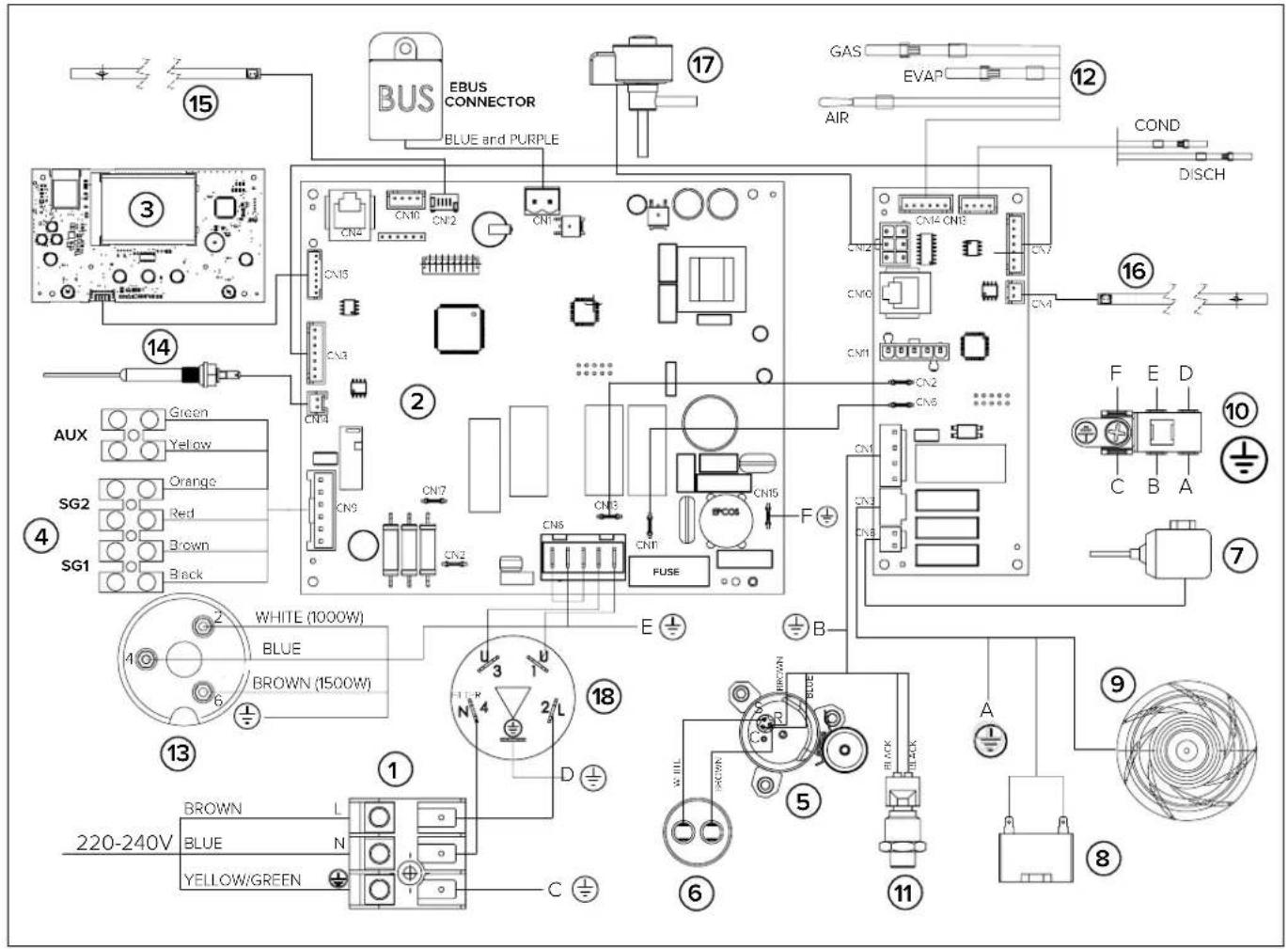
text_image
BUS EBUS CONNECTOR BLUE and PURPLE GAS EVAP AIR COND DISCH ③ ② ① ⑤ ⑪ ⑫ ⑬ ⑭ ⑮ ⑯ ⑰ ⑱ ⑲ ⑳ ㉑ ㉒ ㉓ ㉔ ㉕ ㉖ ㉗ ㉘ ㉙ ㉚ ㉛ ㉜ ㉝ ㉞ ㉟ ㉳ ㉻ ㉒ ㉓ ㉔ ㉕ ㉖ ㉗ ㉘ ㉙ ㉚ ㉛ ㉜ ㉝ ㉞ ㉟ ㉳ ㉟ ㉟ ㉟ ㉟ ㉟ ㉟ ㉟ ㉟ ㉟ ㉟ ㉟ ㉟ ㉟ ㉟ ㉟ ㉟ ㉟ ㉟ ㉟ ㉟ ㉟ ㉟ ㉟ ㉟ ㉟ ㉟ ㉟ ㉟ ㉟ ㉟ ㉟ ㉟ ㉟ ㉟| 1 | Power supply (220-230V 50Hz) |
| 2 | Mainboard (motherboard) |
| 3 | Interface board (display or HMI) |
| 4 | Connection board |
| 5 | Hermetic rotary compressor |
| 6 | Operation condenser (15μF 450V) |
| 7 | Hot gas valve |
| 8 | Condenser fan |
| 9 | Fan |
| 10 | Earth pole |
| 11 | Pressure transducer |
| 12 | Air/Evaporator/Suction NTC temperature probes |
| 13 | Electric heating element (°) |
| 14 | Impressed current anode |
| 15 | Bottom NTC temperature probe (heating element zone) |
| 16 | Top NTC temperature probe (hot water) |
| 17 | Electronic expansion valve |
| 18 | Filter |
INSTALLING THE APPLIANCE
WARNING!
The installation and initial start-up of the appliance must be performed by qualified personnel in compliance with the national regulations in force regarding installation, and in conformity with any regulations issued by local authorities and public health bodies. The installer is required to observe the instructions outlined in this manual. Once installation is complete, it is the installer's duty to inform and instruct the user on how to operate the water heater and carry out the main operations correctly.
Transport and handling
Upon delivery of the product, check that the latter has not been damaged during transport and that no signs of damage appear on the packaging. In the event of damages, immediately notify any claims to the forwarder.
WARNING!
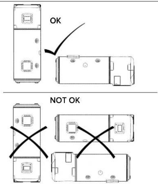
THE APPLIANCE SHOULD BE HANDLED AND STORED IN A VERTICAL POSITION.
The product may be handled in a horizontal position only for short distances, while resting on the rear end indicated; in this case, wait at least 3 hours before starting the appliance once it has been correctly repositioned in a vertical position and/or installed; this is to ensure that the lubricating oil inside the refrigeration circuit is suitably distributed and to avoid damages to the compressor.
text_image
OK NOT OKThe packaged appliance may be handled either manually or with the aid of a forklift truck, while ensuring that the above indications are observed. It is advisable to keep the appliance in its original packaging until installing it in its chosen location, particularly when construction work is under way on-site.
When transporting or handling the appliance after the initial installation, observe the aforementioned indication concerning the allowed tilt angle and ensure that all water has been drained from the tank. Should the original packaging be missing, provide an adequate protection for the appliance to prevent any damages, for which the manufacturer shall not be held liable.
Location of the appliance
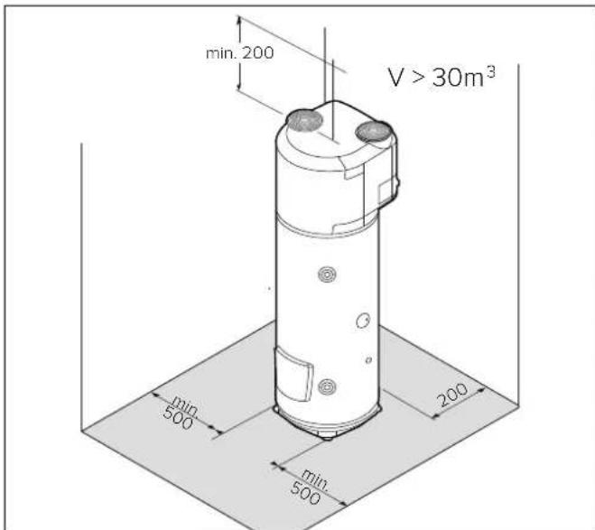
a) In the event of water heaters without an air exhaust duct, the room of installation should have a volume of no less than 30 m3 and must be adequately ventilated. Avoid installing the appliance in rooms which may favour frost build-up.
Do not install the product in a room containing an appliance that requires air to function (e.g. an open chamber gas boiler, open-chamber gas water heater, etc.) unless otherwise indicated by local law. The product's safety and performance levels are not guaranteed in the event of outdoor installation.
b) The appliance's air exhaust and/or extraction duct (if present) must have access to the outside from the point where the appliance is installed. The connections for the air exhaust and aspiration ducts are located on the upper part of the appliance;
c) Ensure that the installation site and the electrical and hydraulic systems to which the appliance must be connected fully comply with the regulations in force;
d) The chosen site must have, or must be suitable to house, a single-phase 220-240 V\~50 Hz power supply socket;
e) The chosen site must be suitable to house a condensate drainage outlet connected to the lateral of the appliance with a suitable siphon;
f) The chosen site must ensure that the appropriate safety distances observed;
g) Ensure that installation of the ducts allows maintenance operations on the evaporator filter;
h) Ensure that the plan allows a perfectly vertical operating position;
i) The chosen site must conform to the appliance's IP protection rating (protection against the penetration of liquids) as specified by the regulations in force;
j) The appliance must not be exposed to direct sunlight, even when windows are present;
k) The appliance must not be exposed to particularly aggressive substances such as acidic vapours, dust or gasfilled environments;
I) The appliance must not be directly installed on telephone lines that are unprotected against overvoltage;
m) The appliance must be installed as close as possible to the points of use to limit heat dispersion along the piping;
n) The air aspirated by the product must be free of dust, acicid vapours and solvents.
Leave adequate space around the appliance in order to ensure easy access and to facilitate maintenance operations. Leave a minimum distance of 500 mm on both sides of the appliance and the minimum height from the ceiling should be approximately 200 mm for operation without air ducts and 230 mm for the operation with air ducts.
Positioning on the ground
1) Once the suitable installation position has been located, remove the packaging and remove the fixings on the pallet where the product is based.
2) Using the handles provided, remove the product from the pallet.
3) Fix the feet on the ground (through the appropriate holes) using suitable screws and rawlplugs.
AIR SUPPLY CONNECTIONS
WARNING!
A type of canalization not suitable affects product performance and significantly increases the heating time!
Please bear in mind that using air from heated environments may hamper the building's thermal performance.
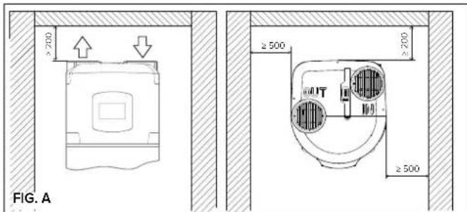
There is one connection for the air intake and one for the air exhaust on the top side of the appliance. Important: do not remove, break or tamper in any way with the air inlet and outlet grilles (Fig. A).
The outlet air may reach temperatures that are 5-10°C lower compared to that of the inlet air and, if not ducted, the temperature of the room of installation may drop sensibly.
If operation by exhaust or intake to the outside (or another room) of the treated air by the heat pump is foreseen, suitable ducting must be used for air passage.
IMPORTANT: we recommend using insulated pipes to avoid the formation of condensation.
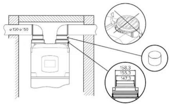
Ensure that the ducting is connected and fastened securely to the product to prevent accidental disconnections and annoying noises. Install the ducts by following all the heights as shown in (Fig. B). Leave a minimum distance between the product and the ducts to allow for the removal of the evaporator filter.
WARNING: Do not use outdoor grills resulting in high losses, such as anti-insect grilles.
The grids used should allow good air flow, the distance between the inlet and outlet air should not be less than 370 mm. Protect pipes from the external wind. The expulsion of air in the chimney is allowed only if the draft is appropriate, is also required periodic maintenance of the barrel, and chimney accessories.
For the maximum length of air ducts, including the terminal, please refer to the "Typical Configurations" table.
The total static pressure loss due to installation is calculated by adding the loss of the single installed components; this sum must be lower than the static pressure of the fan (Appendix)
TYPICAL CONFIGURATIONS
| Type | |||||
| Maximum piping lengthL1 exhaust + L2 intake | ø150(PVC) | 22 [m] 19 [m] 16 [m] 19 [m] | |||
| ø160(PEHD) | 28 [m] 24 [m] 20 [m] 24 [m] | ||||
When a curve is added:
- 90^ (PEHD) remove 4 m from the permitted length
- 45^ (PEHD) remove 2 m from the permitted length
- 90^ (PVC) remove 3 m from the permitted length
- 45° (PVC) remove 1.5 m from the permitted length
text_image
≥ 200 ≥ 500 ≥ 200 ≥ 500 FIG. AFIG. B
text_image
ø150ø150 158,3 155,3 147,3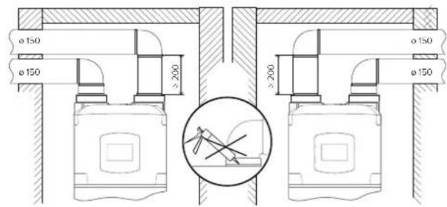
text_image
ø 150 ø 150 ≥200 ≥200 ø 150 ø 150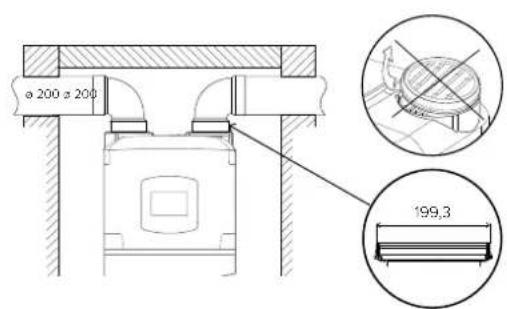
text_image
ø 200 ø 200 199,3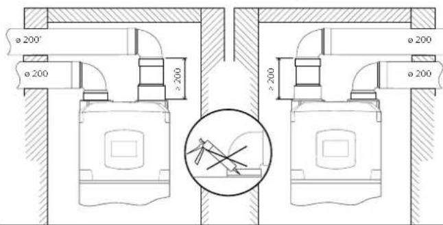
text_image
ø 200° ø 200 ≥200 ø 200 ≥200 ø 200Table with minimum ceiling heights for ducted installation
| Model | 200 l | 250 l |
| ø 150 mm | ≥2050 mm | ≥2310 mm |
| ø 160 mm (PEHD) | ≥2140 mm | ≥2400 mm |
| ø 200 mm | ≥2060 mm | ≥2320 mm |
HYDRAULIC CONNECTIONS
Before using the product, we recommend filling its tank with water and draining it completely so as to remove the residual impurities.
Connect the water heater inlet and outlet to pipes or pipe fittings that can withstand the operating pressure and temperature of the hot water, which may reach 75°C. It is not advisable to use materials that cannot withstand such temperatures. The dielectric union fitting with joint (supplied with the product) must be applied to the hot water outlet pipe, prior to performing the connection.
The appliance must not operate with water hardness levels below 12°F; on the other hand (>25°F), it is advisable to use a suitably calibrated and monitored water softener in the event of particularly hard water; in this event, the residual hardness must not fall below 15°F.
Screw a "T" fitting identified by a blue collar onto the appliance's water inlet pipe.
It is mandatory to screw on said fitting a cock for draining the product with a tool on one side, and a suitable device against overpressure on the other side.
SAFETY GROUP COMPLIES WITH THE EUROPEAN STANDARD EN 1487
Certain countries may require the use of specific safety devices (see next figure for the European Community countries), in line with local legal requirements; it is the responsibility of the qualified installer in charge of installing the product to assess the correctness and suitability of the safety device used.
The codes for these accessories are:
Hydraulic safety assembly 1/2" code 877084 (for products with 1/2" diameter inlet pipes)
Hydraulic safety assembly 3/4" code 877085 (for products with 3/4" diameter inlet pipes)
Trap 1" code 877086
Do not install any shut-off device (valve, cock, etc.) between the safety unit and the heater itself. The appliance's drain outlet must be connected to a drain pipe of diameter at least equal to the of the outlet itself, with a funnel to permit an air gap of at least 20 mm for visual inspection.
In addition, a water discharge tube on the outlet is necessary if the emptying tap is opened.
When installing the safety device, do not tighten it fully down, and do not tamper with its settings. It is necessary to connect the drain, which must always be left exposed to the atmosphere, with a drainage pipe that is installed sloping downwards in a place with no ice. If the network pressure is closed to the calibrated valve pressure, it will be necessary to apply a pressure reducer far away from the appliance. To avoid any possible damage to the mixer units (taps or shower) it is necessary to drain any impurities from the pipes.
The SYS and TWIN SYS versions have a 34 "G coupling for recirculation of the hydraulic system (if present).
The SYS version coil has two 34 "G couplings, upper (inlet) and lower (outlet), on which to connect an auxiliary source.
The TWIN SYS version has two coils on which to connect two different auxiliary generators. For the TWIN SYS version we recommend you connect any solar heating systems to the lower coil and the other heat generator to the upper one.
WARNING! It is advisable to carefully wash the system's pipes in order to remove any residues of screw thread, welding or dirt which may hamper the correct operation of the appliance.
LEGIONELLA BACTERIA FUNCTION
Legionella are small rod shaped bacteria which are a natural constituent of all fresh waters.
Legionaries' disease is a serious pneumonia infection caused by inhaling the bacteria Legionella pneumophilia or other Legionella species.
This bacterium is frequently found in domestic, hotel and other water systems and in water used for air conditioning or air cooling system. Hence the main intervention against the condition is prevention, through control of the organism in water systems.
The European standard CEN/TR 16355 gives recommendations for good practice concerning the prevention of Legionella growth in drinking water installations but existing national regulations remain in force.
This storage water heater is supplied with the thermal disinfection cycle deactivated by default. Each time the product is turned on and every 30 days, the system carries out a thermal disinfection cycle raising the temperature of the boiler to 60°C.
Warning: when this software has been carrying out the thermal disinfection treatment, water temperature can cause severe burns instantly. Children, disabled and elderly are at highest risk of being scalded. Feel water before bathing or showering.
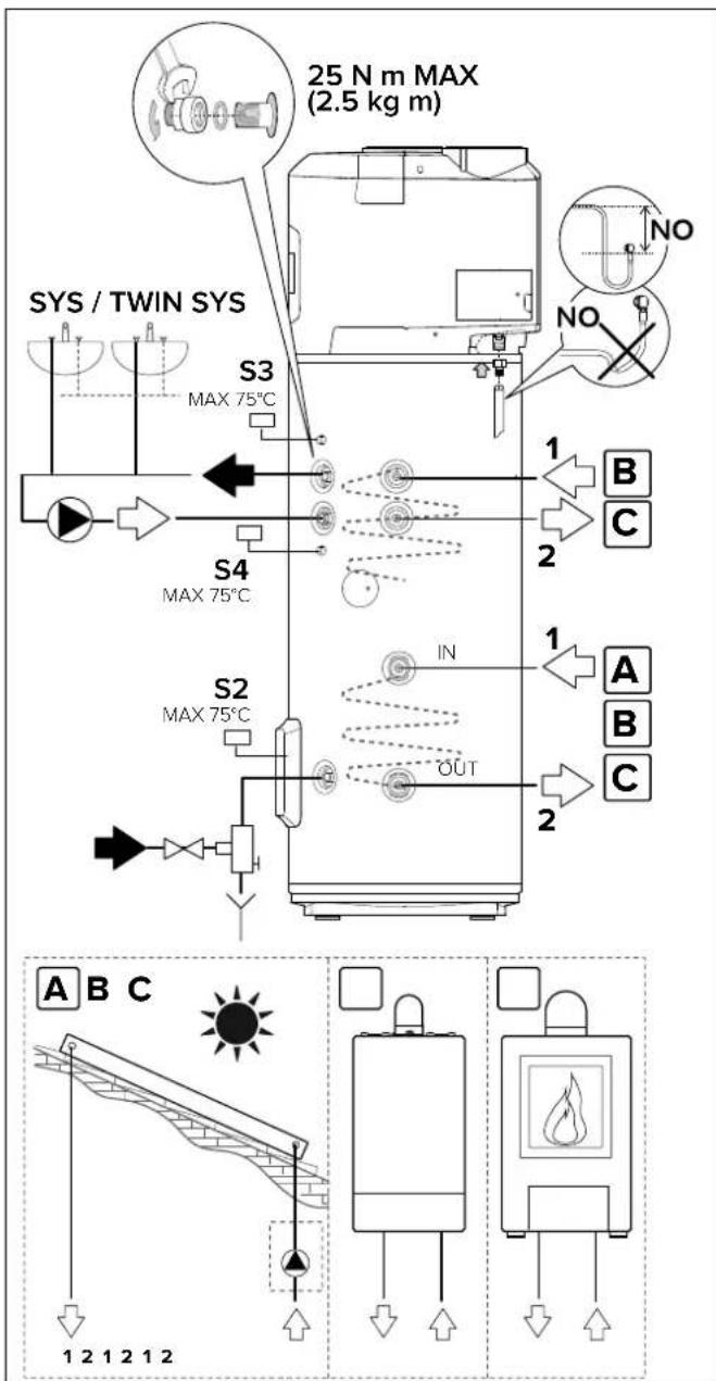
text_image
25 N m MAX (2.5 kg m) SYS / TWIN SYS S3 MAX 75°C S4 MAX 75°C S2 MAX 75°C IN OUT 1 2 B C 1 A B C A B C 1 2 1 2 1 2WARNING! (only for SYS and TWIN SYS versions)
Make sure that the temperature detected by the S2, S3 and S4 sensors of the auxiliary-source control unit inside the water heater, does not exceed 75°C.
ELECTRICAL CONNECTIONS
WARNING!
Before you get access to terminals, all supply circuits must be disconnected.
The appliance is supplied with a power supply cable (should the latter need to be replaced, use only original spare parts supplied by the manufacturer).
It is advisable to carry out a check on the electrical system to verify conformity to the regulations in force. Verify that the electrical system can suitably withstand the water heater's maximum power consumption values (refer to the data plate), in terms of the size of the cables and their conformity to the regulations in force.
It is forbidden to use multiple outlet sockets, extension cables or adaptors. It is forbidden to use piping from the water, heating and gas systems for earthing the appliance. Prior to operating the machine, make sure that the electricity mains voltage conforms to the value indicated on the appliance's data plate. The manufacturer of the appliance shall not be held liable for any damage caused by failure to earth the system or due to anomalies in the electric power supply. To disconnect the appliance from the mains, use a bipolar switch complying with all applicable CEI-EN regulations in force (minimum distance between contacts 3 mm, switch preferably equipped with fuses). The appliance must be connected in compliance with European and national standards (NFC 15-100 for France). The main circuit board on the appliance is fitted with an earth contact for operating purposes only, not for safety purposes.
Open the cover to access the connection board located on the right, rear side of the product and carry out the connections according to the chosen configuration:
PERMANENT ELECTRICAL CONNECTION (24h/24h)
Use this configuration whenever users do not have a two-tier electricity rate. The water heater will always be connected to the power supply network to ensure 24h operation.
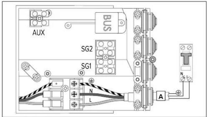
text_image
AUX BUS SG2 SG1 N L A NELECTRICAL CONNECTION WITH DUAL POWER SUPPLY AND HC-HP SIGNAL (power supply 24h/24h)
It offers the same cost advantages as the two-tier rate configuration but, additionally, it provides rapid heating thanks to the BOOST mode that activates the heating even with the HP rate.
1) Connect a bipolar cable to the appropriate signal contacts on the meter.
2) Connect the signal bipolar cable (B) to the appropriate EDF connector "SG1" which is inside the connection box (make a hole in the rubber plugs to create a suitable passage section).
WARNING: The EDF signal has a 230V voltage.
3) Activate the HC-HP function through the P1 parameter in the installer menu.
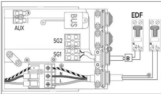
text_image
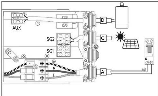
AUX BUS SG2 SG1 N L EDF B N 2 A N EAUXILIARY CONNECTION
If you have a PV system to be connected or an SG signal available, you can connect a bipolar cable from the inverter or the SG signal cable (alternatively, not both) to the connection box (secure the cable into the dedicated cabling sheath).
Connect this cable (C) to the connector called "SG2" and activate the PV (P11) or SG (P13) function via the installer menu.
WARNING: signal 230 V.
Only for SYS or TWIN SYS models, if you have an auxiliary heat generator (e.g. boiler) and you would like to use it instead of the integration carried out by the heating element, you can connect a bipolar cable (D) from the heat generator (if provided) to the product connection box (secure the cable into the dedicated cabling sheath).
Connect the cable to the connector called "AUX" and set the P14 parameter to 1 via the installer menu.
text_image
AUX SG2 SG1 N L D C A N (高电)If you connect the SYS version to the boiler/stove, it is advisable to use upper sensor slot S3.
If you connect the TWIN SYS version to the boiler/stove, it is advisable to use sensor slot S4 for the lower heat exchanger and S3 for the upper one).
If you connect the SYS or TWIN SYS versions to the solar control unit (lower heat exchanger), you can use the lower sensor slot on its own (S2) or both sensor slots (S2) and (S3/S4).
| CABLE FUSE | |||
| Permanent power supply (cable supplied with the appliance) | 3G min. 1.5 mm ^2 H05VV-F B 16A | ||
| Signal HC-HP (cable not supplied with the appliance) | 2G min. 1 mm ^2 H05VV-F | ||
| Signal AUX/PV/SG (cable not supplied with the appliance) | 2G min. 1 mm ^2 H05VV-F | ||
| Signal BUS* (cable not supplied with the appliance) | max. 50 m - 2G min. 1 mm ^2 | ||
* IMPORTANT: in the bus connection, to avoid interference problems, use a shielded cable or twisted pair cable.
Bus BridgeNet®
START WIZARD
This product is compatible with Bus BridgeNet®.
Set the SYSTEM and CASCADE parameters as indicated below for correct installation on BUS during the start phase:
- SYSTEM = NO
The product is not connected on BUS or is only connected to a remote control.
- SYSTEM = YES Cascade = NO
The product is installed on a system on bus with other compatible heat generators (solar heating, boiler, hybrid system or heat pump), at least one of which is powering the BUS. In presence of a Wi-Fi gateway on BUS (installed on remote control or on heat generator), the heating and domestic hot water services can be managed via a single app for smartphones.
- SYSTEM = YES Cascade = YES
The product is installed on a cascade system (max 8) for commercial or collective use. After setting the CASCADE option, confirm whether the product is the MASTER or one of the cascade SLAVES. The BUS allows you to align all the user operating parameters on the MASTER product with those on the SLAVE products.
The SYSTEM and CASCADE parameters affect the P33 and P34 parameters of the installer menu.
If the product is enabled to work on BUS in order to avoid risks of a power overload, the product will not power the BUS (P33 parameter of the installer menu set to OFF), except for when the product is a cascade MASTER. It is therefore necessary to have at least another generator which powers the BUS to complete the start phase.
When the product is installed on BUS, all the parameters for the management of domestic hot water, its special parameters and the system parameters are shared with all other products, allowing you to use just one remote control.
BUS CONNECTION
Connect a cable to the "BUS" connector to manage the heat pump water heater with a single remote control on BUS together with other compatible heat generators.
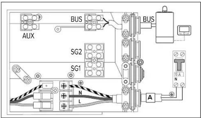
text_image
AUX BUS SG2 SG1 BUS T N A N
flowchart
graph TD
    A["EBuS CONFIG"] -->|SET >>| B["n0 SYSTEM"]
    B -->|- > +| C["YES SYSTEM"]
    C --> D["n0 CASCADE"]
    D -->|- > +| E["YES CASCADE"]
    E -->|SET SE >>| F["SL 7 HP TYPE"]
    F -->|- > +| G["NAST HP TYPE"]
    G -->|SET >>| H["INITIZATION"]
    H --> I["NITALIZATION"]
    I --> J["ERROR"]
    J --> K["↑ PRESS THE MENU BUTTON AND REPEAT THE CONFIGURATION PROCEDURE"]
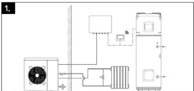
INSTALLATION TYPES WITH OTHER HEAT GENERATORS
1. Heat pump water heater and separate heat generator (boiler, heat pump or hybrid system).
The products have no integration but can be managed via a single remote control.
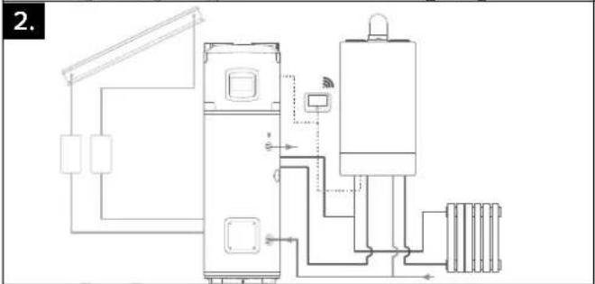
2. Heat pump water heater with auxiliary generator (boiler and/or solar system) with coil.
If the system is installed with a boiler acting as a support generator, in order for the heat pump water heater to call the boiler as opposed to the heating element via the BUS, you must set the P14 parameter to value 3 (consult INSTALLER MENU section).
Unless otherwise specified in the auxiliary generator manual, the auxiliary generator does not read the water heater sensors; therefore additional sensors are required depending on the hydraulic circuit diagram.
3. Heat pump water heater in pre-heating of combined heating generator (boiler or combi hybrid).
In order to enable the pre-heating management on the domestic hot water service, set the P14 parameter to 2. In this installation, the water heater and the combi generator share the same DHW temperature setting. The water heater temperature can be reduced in pre-set time slots using the T MIN parameter or increased using the PV SET parameter if there is a photovoltaic system.
The combi generator does not read the sensors of the water heater. Additional sensors are required, depending on the hydraulic circuit diagram.
text_image
1.
natural_image
Pure electrical circuit lines without any symbols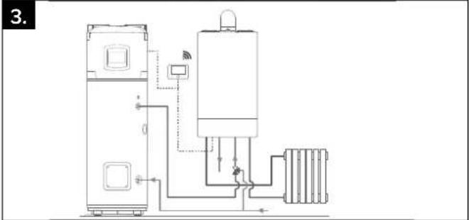
natural_image
Pure electrical circuit lines without any symbolsSTART-UP
WARNING!
The installation and initial start-up of the appliance must be performed by qualified personnel in compliance with the national regulations in force regarding installation.
CONTROL PANEL
The user interface has LCD display and 7 touch buttons. There are 2 blue leds: ON (when the product is power supplied) and BOOST (when BOOST has been activated).
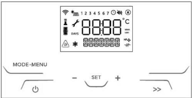
text_image
1 2 3 4 5 6 7 °C DAYS 88:00 Min W MODE+MENU - SET + >>List of the icons shown on the display:
| Changeable parameter | |
 | Wi-Fi enabled (only if present) |
 | Schedule programming enabled |
 | Day of the week (1 = Sunday) |
 | Heat pump active |
 | Heating element integration enabled |
 | ANTIBACTERIAL function is enabled |
 | PV or SG enabled (only if present)When the corresponding mode is active, the secondary string indicates it |
 | |
 | SILENT function is enabled |
 | ANTIFREEZE function is enabled |
 | Top temperature sensor > T SETPOINT + 6°C |
 | Hot water shower available |
 | Estimated Energy Content(based on the set temperature) |
 |
Once the appliance is connected to the hydraulic and electric systems, the water heater must be filled with water from the domestic water supply network. In order to fill the water heater, it is necessary to open the central tap of the domestic network supply and the nearest hot water tap, while making sure that all the air in the tank is gradually expelled. Visually inspect for possible water leaks from the flange and pipe fittings and gently tighten them, if necessary. The heat pump requires 5 minutes to become fully operational when starting it for the first time.
WARNING! Hot water at temperatures above 50 °C running from taps may immediately cause serious burns. Children, the disabled and the elderly run a greater risk in this regard. Therefore, it is advisable to use a thermostatic mixing valve connected to the appliance's water outlet pipe, which is identified by a red collar.
WARNING!
If the water temperature is higher than the set temperature by 6^ C,
the display shows the icon

INSTRUCTIONS FOR USE
Press the "button to turn the water heater on. The display shows the set temperature and operation mode, while the "HP symbol and/or " symbol indicate the operation of the heat pump and/or heating element respective. Press the "button for 1 second to switch off the water heater. The protection against corrosion is ensured. The product ensures that water temperature inside the tank does not fall below 5°C.
SETTING THE TEMPERATURE
Press the “+” and “-” to set the desired hot water temperature (T SET POINT, the display will temporarily flash).
Press "SET" button to display the temperature of the water in the tank; it will be shown for 3 seconds.
In heat pump mode the min/max temperatures achievable are 40^ C/55°C, by default settings. This range can be extended (min/max 40^ C/62°C) in the installer menu. The maximum achievable temperature with the heating element is 75 °C. Changing the settings on the installer menu this value can vary.
SHOWERS AVAILABLE

When the display shows the icon, it means that at least one shower is available. The available showers depend on the availability of hot water. One shower is calculated as: 40 l at 40°C.
MODE OF OPERATION
With the "MODE ←" button you can modify the operating mode used by the water heater to reach the set temperature. The selected mode will be displayed on the line below the temperature.
If the heat pump is active, this symbol appears "HP♣" If the electric heating element or integration is enabled, this symbol will appear "-W".
- GREEN
only the heat pump works, the priority is given to energy saving. The maximum achievable temperature depends on the value of the P7 parameter (40°C-62 °C) – (refer to Paragraph 7.7). Only for back-up or safety mode (errors, air temperature out of operating range, defrosting process in progress, antilegionnaire's disease), the heating element may turn on and work.
• COMFORT
the water heater reaches set temperature with the rational use of the heat pump and, only if necessary, of the heating element. The priority is given to comfort.
- FAST
permanent boost mode, the water heater uses both heat pump and heating element to reach set temperature. The priority is given to heating time.
- I-MEMORY
mode designed to optimize energy consumption and maximize comfort by monitoring the hot water needs of the user and the optimized use of the heat pump/heating element. The algorithm guarantees each daily need proposing the average of the profiles detected over the previous 4 weeks. In the first week of acquisition, the set point temperature entered by the user remain constant; from the second week onwards, the algorithm will automatically adjust the set point temperature to ensure daily needs. To reset the I-Memory profile use U9. (IMemory mode is visible when U1: PROGRAM is "OFF")
HC-HP
mode heating is performed within HC-HP signal detection in order to heat when low-tariff energy is available. The target temperature depend on the particular HC-HP mode selected:
- HC-HP: when signal EDF is detected, HP and HE can work (priority is given to HP). Antifreeze protection is guaranteed all day long.
- HC-HP_40: when signal EDF is detected it works as HC-HP, otherwise temperature is maintained at 40°C (HP only)
- HC-HP24h: when signal EDF is detected it works as HC-HP, otherwise set temperature is achieved with
HP only (min/max 40/62°C)
The mode can be activated via the installer menu with the P1 parameter.
- BOOST (button " >>")
both heat pump and heating element are used to reach the set temperature in the shortest possible time. Once set temperature is reached, previous working mode is reactivated.
• HOLIDAY
o be used during a period of absence. After the period chosen Holyday mode is deactivated and the product will automatically start to work according to previous setting. Holiday mode is set by User Menu. In this mode no heating is performed, antifreeze protection and antibacterial cycle are guaranteed.
USER MENU
To access the user menu, press "MENU".
The word INFO will appear on the display. Press the “+” and “-” buttons to scroll the parameters U1, U2, U3 ... U10, the description of the parameter is shown in the line below. Once you have chosen the parameter press the “SET” button to select it. To go back to the parameter selection, press the “MODE↔” button.
PARAMETER
NAME PARAMETER DESCRIPTION
| U1 PROGRAM | It selects different operating modesPROGRAM ON - TIME BASED:GREEN, COMFORT, FASTPROGRAM OFF - ALWAYS ACTIVE:GREEN, COMFORT, FAST, AUTO, HC-HP |
U2 PRGTIME User can select the desired time slots.
U3 PRG SET User can customize the time programming
| U4 HOLIDAY | To activate/deactivate the HOLIDAY modeWhen On is confirmed the user has to enter the number of days of absence as “Holiday Days” [1, 99] |
| U5 ANTBACT | Activated/deactivated status of the antibacterial function disease function (on/off). |
| U6 DATE | To set the date (Year, Month, Day) and time (hours and minutes). User can enable/disable the auto switch among solar/legal hour. |
| U7 REPORTS | It displays energy consumption (total). |
| U8 SILENT | To enable/disable the SILENT mode (On/Off)Recommended for unducted installation. |
| U9 I-MRESET | To reset the delivery profiles select On and press the SET button.The data saved in the memory is deleted and the learning starts from the current week. |
| U10 WIFI RS | WHERE AVAILABLETo reset the Wi-Fi data, select On and press the SET button. |
• TIME SCHEDULING
U2 PRGTIME parameter.
the user can set 4 different time slots for each day of the week in the operating modes GREEN, COMFORT e FAST.
[START] and [STOP] define the beginning and the end of a time slot. After the fourth time slot, to reset the time slot selected and the ones after, press " " - " until "OFF" is displayed and then press "SET". If a time slot is not set it remains as not defined.
Example: the water heating system is active from 8 am to 12 pm and from 4 pm to 8 pm.
[START1] = 8:00; [STOP1] = 12:00;
[START2] = 16:00; [STOP2] = 20:00;
[START3] = 00:00; [STOP3] = 00:00;
[START4] = 00:00; [STOP4] = 00:00;
If ALL_DAYS is selected the same time slots are assigned from Monday to Sunday. Then each day of the week can be customized
one by one, selecting the corresponding parameter.
Therefore, each day of the week can be customised one by one by selecting the corresponding parameter.
Warning: if the selected time period is too short, the desired temperature may not be reached.
• PROGRAM SETTINGS
U3 PRG SET parameter. Program Setting allows to customize the different working modes when U1 is ON.
| PARAMETER | NAME PARAMETER DESCRIPTION | |
| U3.1 | T MIN | Beyond the time slot, a minimum water temperature is guaranteed.Heat pump to pre-heat water:the set temperature is reached at the beginning of the selected time slots. |
| U3.2 | PREHEAT | Heat Pump pre-heat the water: set temperature is already achieved at the beginning of the selected time slots |
INSTALLER MENU
CAUTION!
THE FOLLOWING PARAMETERS MUST BE ADJUSTED BY QUALIFIED PERSONNEL
The main product settings can be modified via the installer menu. The changeable parameters are shown on the display together with the key symbol "√".
To enter the installer menu press the "MENU" button for 3 seconds, press the "+" and "-" buttons and enter the access code 234.
| PARAMETER | NAME PARAMETER DESCRIPTION | |
| P0 | CODE | Entering the code to access the installer menu. The display will show the number 222, press the “ + ” and “ - ” and enter the code 234, press the “SET” button to confirm.It will then be possible to access the installer menu. |
| P1 | HC-HP | Operation with two-tier power supply:0. HC-HP_OFF (disabled default)1. HC-HP2. HC-HP_403. HC-HP24h |
| P2 | ANTIBACT | To disable/enable the antibacterial functionON (function enabled)OFF (function disabled) |
| P3 | T ANTB | Gives the temperature to be achieved [60/75 °C] with the antibacterial cycle and to be maintained for 1 hour at least. |
| P4 | T MAX | Adjustment of the maximum obtainable temperature [65 / 75 °C]. A higher temperature value allows for using a greater amount of hot water. |
| P5 | T MIN | Adjustment of the minimum obtainable temperature [40 /50 °C]. A lower temperature setting allows for more energy-efficient operation in the event of limited hot water consumption. |
| P6 | I-M TMIN | Minimum temperature to be guaranteed in I-Memory mode when no withdrawals have been detected by the algorithm |
| P7 | TMAX HP | Maximum water temperature that can be achieved with the heat pump only. It can be set by the installer in the [40 / 62 °C] range. |
| P8 | TMINAIR | Minimum air temperature that ensures the heat pump working; if air temperature goes below this value the compressor is inhibited. It can be set by the installer in the [-10, 10°C] range |
| P9 | HYST HP | Hysteresis value that allows the heat pump to restart after having achieved the target temperature. It can be set by the installer in the [3 / 12°C] range. |
| P10 | TANKVOL | This parameter gives the capacity of the tank; it is useful in case of spare part customization. |
| P11 | PV MODE | Operation with PV:0. OFF (PV disabled - default)1. PV_HP (PV with HP only)2. PV_HE (PV with HP and HE1)3. PV_HEHP (PV with HP and HE1 + HE2) |
| P12 | PV TSET | This parameter gives the temperature to be achieved in PV mode. It can be set by the installer in the [55 / 75 °C] range. |
| P13 | SG MODE | Operation with SG:0. OFF (SG disabled - default)1. HP_ON (SG enabled with HP only) |
| P14 | SYSMODE | System Operation:0. STD (standard installation)1. OUT (The product is configured to operate with a coil auxiliary load controlled by the direct AUX contact)2. PRHE (The product is configured as a generator in pre-heating to operate with an auxiliary load and share the domestic hot water parameters)3. SYS (The product is configured to operate with a coil auxiliary load controlled via Bus) |
| P15 | BUZZER Buzzer beep at buttons pressure | |
| P16 | SILENT | Enable/disable the SILENT modeON (function enabled)OFF (function disabled) |
| P18 | FACT RS | Restoring the factory settingsAll the user settings will be reset to default values with the only exception of energy statistics, tank volume and Wi-Fi (if present) |
| P19 | MB SW HP-TOP-MB software version as MM.mm.bb. | |
| P20 | HMI S HP-MED-HMI software version as MM.mm.bb. | |
| P21 | T LOW | Gives the water temperature in °C read by the NTC placed at low position in the water tank.If the NTC is in error “-” is shown |
| P22 | T HIGH | Gives the water temperature in °C read by the NTC placed at high position in the water tank.If the NTC is in error “-” is shown |
| P23 | T DOME | Gives the water temperature in °C read by the NTC placed at dome position in the water tank.If the NTC is in error “-” is shown |
| P24 | T AIR | Gives the air temperature in °C read by the NTC placed on the outside unit.If the NTC is in error “-” is shown |
| P25 | T EVAP | Gives the gas temperature in °C read by the NTC placed before the evaporator on the outside unit.If the NTC is in error “-” is shown |
| P26 | T SUCT | Gives the gas temperature in °C read by the NTC placed before the compressor on the outside unit.If the NTC is in error “-” is shown |
| P27 | T COND | Gives the gas temperature in °C read by the NTC placed after the condenser on the outside unit.If the NTC is in error “-” is shown |
| P28 | T DISC | Gives the gas temperature in °C read by the NTC placed after the compressor on the outside unit.If the NTC is in error “-” is shown |
| P29 | T SH | Gives the superheating temperature in °C. If the NTC evap or suction are in error “-” is shown |
| P30 | ERRORS Allows navigation among last 10 errors that occurred | |
| P31 | WI-FISET | The Wi-Fi function (if available) can be set to:ON (function enabled)OFF (function disabled) |
| P32 | F ANTB | Repetition every [1-30] days for the antibacterial cycle if active |
| P33 | EBUS POWER | ON (function enabled) - OFF (function disabled) |
| P34 | HP-TYPE Cascade setting [Master-Slave1,......Slave7] | |

• P11 PARAMETER - PHOTOVOLTAIC MODE "
If you have a photovoltaic system, you can set the product to optimise use of the electricity produced. After having done the electrical connections as described in paragraph 4.11 fig. 14 and set the P11 parameter to other than "O".
The signal should be received at least for 5 minutes to enable the photovoltaic function (once the product starts a cycle, it will operate for at least 30 minutes).
When the signal is detected, the operating mode works as follow::
- OFF (value 0 - default)
PV mode disabled
- PV\_HP (value 1)
When the signal from the inverter is present. The product will reach the set temperature (the highest between T SET POINT and PV TSET) with only the heat pump (max 62°C).
- PV HE (value 2)
The product will reach the set temperature (the highest between T SET POINT and PV TSET) operating with only the heat pump up to 62°C and if needed with the heating element (1500 W).
- PV\_HEHP (value 3)
set temperature (the highest between T SET POINT and T W PV) is achieved with the heat pump and the heating element (1000 W) up to 62°C. For higher Temperatures than 62 °C the second heating element (1500 W) is activated.
• P13 PARAMETER - SG FUNCTION
If you have an SG signal, you can connect the signal cable as described in the "electrical connections" chapter when the function P13 is enabled the SG icon will be displayed.
Once the SIG2 signal has been received for at least 5 minutes (once the product starts a cycle, it will work for at least 30 minutes), the name of the selected mode alternates with the text SG ON and the current operating mode is automatically changed by thermostating the product at set temperature (the maximum between T SET POINT and PV TSET), operating only with the heat pump (max 62^ ).
• P16 PARAMETER - SILENT
This function reduces the sound level (performance can vary from those declared). It can be enabled via the P16 parameter on the installer's menu. Once activated, the symbol appears on the display

ANTI-FROST FUNCTION
If the temperature of the water in the tank falls below 5 °C while the appliance is powered, the heating element (1000 W) will be automatically activated to heat the water up to 16 °C.
DEFROST

The defrost function is activated when the heat pump has been working for at least 20 minutes, the detected air temperature is below 15^ and the evaporator temperature is decreasing rapidly. When the defrost cycle is running, the icon to the side is displayed.
DEFAULT SETTINGS
The appliance is manufactured with a series of default modes, functions or values, as indicated in the table below:
| PARAMETER | FACTORY DEFAULT SETTING |
| WORKING MODE | GREEN |
| DEFAULT SET TEMPERATURE | 55 °C |
| MAX. TEMPERATURE SETTABLE WITH THE HEATING ELEMENT | 75 °C |
| MINIMUM SETTABLE TEMPERATURE | 40 °C |
| MAX. TEMPERATURE SETTABLE WITH THE HEAT PUMP | 62 °C |
| ANTIBACTERIAL PROTECTION | DEACTIVATED |
| HOLIDAY MODE | DEACTIVATED |
| DEFROST (active defrost activation) | ACTIVATED |
| HC-HP (two-tier rate operation mode) | DEACTIVATED |
| HYSTERESIS | 12°C |
FAULTS
As soon as a fault occurs, the appliance enters into the fault mode while the display emits flashing signals and visualises the error code. The water heater will continue supplying hot water if the fault affects only one of two the heating units, by activating the heat pump or heating element. If the fault involves the heat pump, the symbol "HP" will flash on the screen, while the heating element symbol will flash if the fault involves it. If both components are affected, both symbols will flash.

CAUTION!
Before intervening on the product by following the indications below, check the correct electrical connection of the components to the mainboard and the correct position of the NTC sensors in their seats.
| Error code | Cause | Heating element operation | Heat pump operation | What to do |
| 007 | NTC Condenser: Open or Short Circuit ON OFF Verify NTC | Condenser proper functioning | ||
| 008 | NTC Discharge (Compressor Outlet):Open or Short Circuit | ON OFF Verify NTC Discharge proper functioning | ||
| 009 | NTC Air: Open or Short Circuit ON OFF Verify NTC Air proper functioning | |||
| 010 | NTC Evap: Open or Short Circuit ON OFF Verify NTC Evap proper functioning | |||
| 012 | NTC Suction (Compressor Inlet): Open or Short Circuit | ON | OFF | Verify NTC Suction proper functioning |
| 021 | Gas Leak ON OFF | Verify compressor inlet sensor proper functioning. If the error persists, recover residual gas; find the leak in the cooling circuit; repair it; make vacuum and recharge circuit with 1100g of refrigerant gas | ||
| 032 | Compressor Issue ON OFF Check power voltage on compressor connector. | |||
| 042 | Evaporator Obstructed ON OFF | Turn off the appliance.Check that the evaporator and the external unit casing is not obstructed. | ||
| 044 | Fan Issue ON OFF | Check power voltage on fan connector.Control the proper functioning of sensor at compressor inlet. | ||
| 051 | High Pressure ON OFF Check pressure switch wiring. Verify gas quantity. | |||
| 053 | Compressor Thermal Protector: KO | ON | OFF | Check compressor connector. |
| 081 | Electronic Expansion Valve Issue ON OFF | Verify expansion valve cables. Verify NTC suction and NTC Evap correct functioning. | ||
| 218 | Dome NTC sensor (hot water): Open or Short Circuit | ON | OFF | Verify NTC sensor (hot water) proper functioning |
| 230 | Water Temperature Sensor (Heating Element Zone): Open or Short Circuit | OFF | OFF | Check the correct assembly of sensor wiring on related mainboard connector.Verify sensor proper functioning. |
| 231 | Water Temperature sensor (Heating Element Zone): safety intervention (1st level). | OFF | OFF | Verify sensor proper functioning. |
| 232 | Water Temperature sensor (Heating Element Zone): safety intervention (2nd level). | OFF | OFF | Verify sensor proper functioning. |
| 233 | Relay blocked | OFF | OFF | Reset the appliance by pressing the ON/OFF button twice. If the error persists, replace the motherboard. |
| 241 | Impressed Current Anode: Open Circuit | OFF | OFF | Check the presence of water inside the product.If the error persists, verify the anode proper functioning. Check the correct assembly of anode wiring on related mainboard connector.If the error persists, replace mainboard. |
| 314 ON / OFF repeated OFF OFF Wait 15 minutes before unlocking the product with ON/OFF button | ||||
| 321 Corrupted data OFF OFF | Reset the product by pressing the ON / OFF button twice.If the error persists, replace the motherboard. | |||
| 331332 | Missing communication between Main Board and HMI OFF OFF | Reset the product by pushing the ON/OFF button twice. If the error persists, replace the mainboard-display communication wiring. | ||
| 333 Mainboard – WiFi board missing communication ON ON | If WiFi present:- Check cables between motherboard and HMI.- If the error persists, replace the HMI module.If WiFi not present:- Enter to the Installer Menu and set P31 OFF.- If the error occurs again, replace the Main Board. | |||
| 334 | Missing Communication between Inverter and main board | ON | OFF | Check the communication cable and the related motherboard and TDC cables.If the error persists, replace the TDC. |
| 335 Safety board communication failure OFF OFF | Reset the product by pressing the ON / OFF button twice.If the error persists, replace the motherboard. | |||
| 336 Touch screen not working ON ON | Reset the product by pressing the ON / OFF button twice.If the error persists, replace the HMI. | |||
| 337 Cascade master missing OFF OFF | Check that at least one of the products in the cascade is set as Master, otherwise set one. | |||
MAINTENANCE (for authorized personnel)
WARNING!
Observe the general warnings and safety instructions listed in the previous paragraphs and strictly adhere to the indications therein contained.
All maintenance operations and interventions should be performed by qualified personnel (i.e. with the necessary requirements as outlined in the applicable norms in force).
After routine or extraordinary maintenance, we recommend filling the appliance's tank with water and draining it completely to remove any residual impurities.
Use only original spare parts from technical assistance centres that are authorised by the manufacturer.
DRAINING THE APPLIANCE
The appliance must be drained if left inactive in a room subject to frost. When necessary, empty the appliance as follows:
- Permanently disconnect the appliance form the mains electricity;
- Close the shut-off valve, if installed, or the central tap of the domestic water supply network;
- Open the hot water tap (washbasin or bathtub);
- Open the cock on the safety device (in countries which acknowledge EN 1487) or the special cock installed on the "T" fitting, as described in paragraph "Hydraulic connection".
ROUTINE MAINTENANCE
Partial obstruction of the evaporator filter causes a reduction in product performance. We therefore recommend cleaning the filter to remove any dust or obstructions at least once a year.
natural_image
Interior view of a medical imaging machine with transparent plastic cover (no visible text or symbols)
natural_image
Close-up of a person opening a document or folder (no visible text or symbols)The filter can be extracted using the appropriate clip above the casings. Clean the filter with water and mild soap. Verify that the external terminal of the air exhaust duct, and the duct itself, are not obstructed or have not deteriorated. Ensure that the condensate water runs out in a suitable drain and make sure the discharge is made without hindrance.
Check and clean canalizations and grills.
ROUTINE MAINTENANCE PERFORMED BY USERS
It is advisable to rinse out the appliance after each routine or extraordinary maintenance intervention.
The pressure safety device must be operated regularly to verify that it is not clogged and to remove any limescale deposits.
Check that the condensate drainage pipe is not obstructed.
WATER HEATER DISPOSAL
The appliance contains refrigerant gas which must not be released into the atmosphere. In case of permanent decommissioning of the water heater, ensure that disposal procedures are carried out by qualified personnel only.
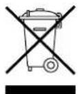
This product conforms to WEEE Directive 2012/19/EU.
The barred bin symbol on the appliance and its packaging indicates that the product must be scrapped separately from other waste at the end of its service
life. The user must therefore hand the equipment over to a sorted waste disposal facility for electro-technical and electronic equipment at the end of its service life. Alternatively, the equipment may be returned to the retailer at the time of purchase of a new equivalent type of appliance. Electronic equipment of size less than 25 cm can be handed over to any electronics equipment retailer whose sales area is at least 400 m² for disposal free of charge and without any obligation to purchase new product. Sorted waste collection for recycling, treatment and environmentally compatible scrapping contributes to the prevention of damage to the environment and promotes reuse/recycling. For more detailed information on the collection systems available, contact the local waste disposal service or the shop where the product was purchased.
TROUBLESHOOTING
| PROBLEM POSSIBLE CAUSE | WHAT TO DO | |
| The water delivered is cold or insufficiently hot | Temperature setting is low Raise the water temperature setting | |
| Machine malfunctioning | Check for errors on the display and follow the instructions on the "Errors" table | |
| No electrical connection, wires disconnected or damaged | Check the voltage on the power terminals, check the condition of the wires and connections | |
| HC/HP signal missing (if the product is installed with EDF signal cable) | To check the operation of the product start the "Boost" mode; if the outcome is positive check the presence of the HC/HP signal from the meter and check that the EDF cabling is intact | |
| Malfunctioning of the timer for the two-tier rate (if the product is installed with this configuration) | Check the operation of the day/night meter and that the set time is sufficient to heat the water | |
| Insufficient air flow to the evaporator Clean the grilles and ducts regularly | ||
| Product is switched OFF Check the mains power supply. Switch the product ON | ||
| Use of a significant amount of hot water when the product is in heating phase | ||
| Sensor error Check for NTC errors, even occasional ones. | ||
| The water is boiling (with possible steam on the taps) | High level of limescale build-up in the boiler and components | Unplug the power supply, empty the appliance, remove the heating element sheath and clean the limescale from the inside of the boiler, taking care not to damage the enamel on the boiler and the heating element sheath. Reassemble the product in its original configuration. We recommend replacing the flange gasket. |
| Sensor error Check for NTC errors, even occasional ones. | ||
| Reduced operation of the heat pump, electrical heating element is in almost continuous operation | "Time W" value too low Set a lower temperature parameter or a higher "Time W" parameter | |
| Installation performed with non-compliant electricity power supply (voltage too low) | Power the product with the correct voltage | |
| Evaporator obstructed or frozen Make sure that the evaporator is clean | ||
| Problems with the heat pump circuit Check the display for error messages | ||
| 8 days have not passed yet since:- Initial start-up- Time W parameter change.- Power failure. | wait 8 days | |
| Insufficient hot water flow | Leaks or obstructions in the hydraulic circuit | Check the circuit for leaks, check the condition of the deflector on the inlet cold water pipe and the integrity of the delivery hot water pipe |
| Water leaking from the pressure safety device | It is normal for some water to drip from the device during the heating phase | To prevent water from dripping, an expansion vessel must be installed on the delivery system. If the leak continues even after the heating phase, check the calibration of the device and the mains water pressure. Warning: Never obstruct the device's discharge outlet! |
| Increased noise level | Presence of an internal obstruction | Check the moving components of the unit, clean the fan and other moving parts which could cause noise |
| Some components are vibrating | Check the components connected using mobile clamps, ensuring the screws are well tightened | |
| Problems with viewing the display or the display turning off | Failure or electrical connection problems between the motherboard and the interface PCB | Check the connection status and the correct operation of the PCBs. |
| Power failure Check the power supply | ||
| A bad odour is coming from the product | No siphon or siphon is empty | Install a siphon. Ensure it contains the necessary amount of water |
| Abnormal or excessive consumption than expected | Leaks or partial obstruction in the refrigerant gas circuit | Switch the product ON in heat pump mode, use a leak detector for the specific type of gas to ensure there are no leaks |
| Unfavourable environmental or installation conditions | ||
| Evaporator is partially obstructed | Check the condition of the evaporator, grille and conduits to ensure they are clean | |
| Non-compliant installation | ||
| Other | Contact technical assistance | |
ALLGEMEINE
text_image
A C M B D N L E I G H F CEtext_image
Technical diagram of a cylindrical device with numbered components for identificationtext_image
Electrical wiring diagram with labeled components and connections, including color-coded wires, connectors, and indicator lights.natural_image
Technical line drawing of a device rear panel with four views and mounting holes (no text or symbols)text_image
AUX SG2 SG1 N L A Ntext_image
AUX BUS SG2 SG1 EDF 2 A N 15 A N B N L NNEBENANSCHLÜSSE
text_image
AUX SG2 SG1 N L A C D 16 T N• SYSTEM = YES Cascade = YES
text_image
AUX BUS SG2 SG1 N L A BUS 16 A N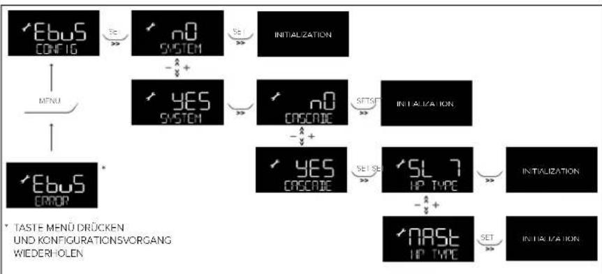
flowchart
graph TD
    A["EBuS CONFIG"] -->|SE >>| B["n0 SYSTEM"]
    B -->|-A +| C["YES SYSTEM"]
    C -->|SE >>| D["n0 CRISCIE"]
    D -->|-A +| E["YES CRISCIE"]
    E -->|SET SE >>| F["SL 7 UP TYPE"]
    F -->|-A +| G["NASL UP TYPE"]
    G -->|SET >>| H["INITIZATION"]
    I["MENU"] --> A
    J["EBuS ERROR"] --> C
    K["TASTE MENU DRÜCKEN UND KONFIGURATIONSVORGANG WIEDERHOLEN"] --> J
INSTALLATIONSARTEN MIT ANDEREN WÄRMEERZEUGERN
natural_image
Pure electrical circuit lines without any symbols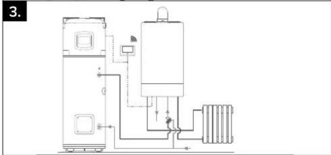
natural_image
Pure electrical circuit lines without any symbolsBETRIEBSMODUS

WARNUNG
- BOOST ( " >> " Taste )
[START1] = 8:00; [STOP1] = 12:00;
[START2] = 16:00; [STOP2] = 20:00;
[START3] = 00:00; [STOP3] = 00:00;
[START4] = 00:00; [STOP4] = 00:00;
natural_image
Interior view of a medical imaging machine with transparent tubing and a technician operating it (no visible text or symbols)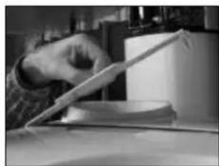
natural_image
Close-up of a hand opening a rectangular object, possibly a device or tool, with no visible text or symbols.BESCHRIJVING VAN HET PRODUCT
text_image
Technical diagram of a mechanical device with numbered components for identificationtext_image
BUS EBUS CONNECTOR BLUE and PURPLE GAS EVAP AIR COND DISCH ⑬ ⑭ ⑮ ⑯ ⑰ ⑱ ⑲ ⑳ ㉑ ㉒ ㉓ ㉔ ㉕ ㉖ ㉗ ㉘ ㉙ ㉚ ㉛ ㉜ ㉝ ㉞ ㉟ ㉳ ㉻ ㉒ ㉓ ㉔ ㉕ ㉖ ㉗ ㉘ ㉙ ㉚ ㉛ ㉜ ㉝ ㉞ ㉟ ㉟A C B A F E D ⑩ ⑪ ⑫ ⑬ ⑭ ⑮ ⑯ ⑰ ⑱ ⑲ ⑳ ㉑ ㉒ ㉓ ㉔ ㉕ ㉖ ㉗ ㉘ ㉙ ㉚ ㉛ ㉜ ㉝ ㉞ ㉟ ㉞A A B C D E F GND100W WHITE (1000W) BLUE BROWN (1500W) WHITE (1000W) BLUE BROWN (1500W) WHITE (1000W) BLUE BROWN (1500W) WHITE (1000W) BLUE BROWN (1500W) WHITE (1000W) BLUE BROWN (1500W) WHITE (1000W) BLUE BROWN (1500W) WHITE (10O0W) BLUE BROWN (1500W) WHITE (1000W) BLUE BROWN (1500W) WHITE (1000W) BLUE BROWN (1500W) WHITE (1000W) BLUE BROWN (1500W) WHITE (1000W) BLUE BROWN (1500W) WHITE (1000W) BLUEINSTALLATIE VAN HET PRODUCT

OPGELET!
text_image
OK NOT OKINLAATCOMBINATIE CONFORM MET DE EUROPESE NORM EN 1487
text_image
AUX SG2 SG1 N L A NELEKTRISCHE AANSLUITING MET DAL- EN PIEKTARIEF EN HC-HP SIGNAAL (24h/24h)
text_image
AUX SG2 SG1 N L EDF B N AHULPVERBINDINGEN
text_image
AUX SG2 SG1 D C 16 A N A L N- SYSTEM = YES Cascade = YES
text_image
AUX BUS SG2 SG1 N L A BUS T 15A N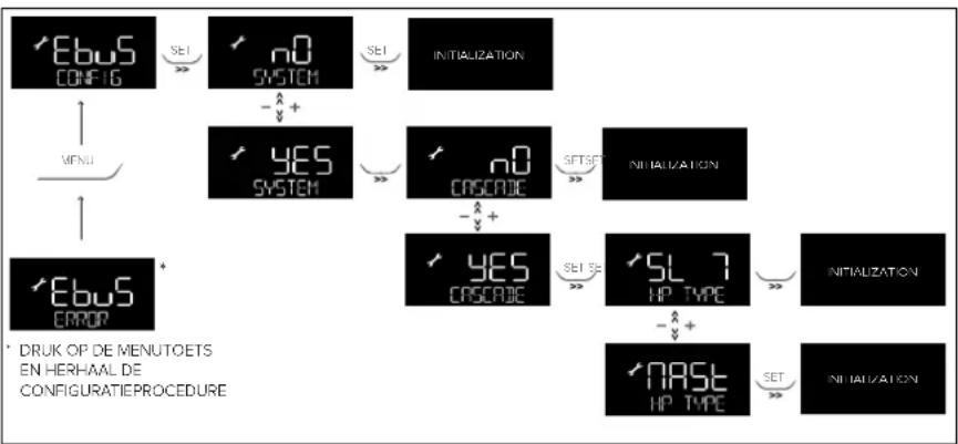
flowchart
graph TD
    A["EBuS CONFIG"] -->|SET >>| B["n0 SYSTEM"]
    B -->|-↑+| C["YES SYSTEM"]
    C --> D["n0 CASCADE"]
    D -->|-↑+| E["YES CASCADE"]
    E -->|SET SE >>| F["SL 7 HP TYPE"]
    F -->|-↑+| G["NAST HP TYPE"]
    G -->|SET >>| H["INITIZATION"]
    H --> I["NITALIZATION"]
    I --> J["ERROR"]
    J --> K["* Druk OP DE MENUTOETS EN HERHAAL DE CONFIGURATIEPROCEDURE"]
    A --> L["MENU"]
    L --> M["EBuS ERROR"]
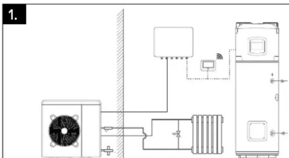
text_image
1.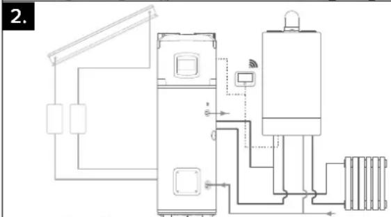
natural_image
Pure electrical circuit lines without any symbols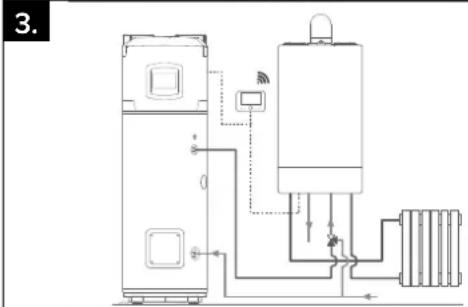
text_image
3.EERSTE INBEDRIJFSTELLING

OPGELET!
[START1] = 8:00; [STOP1] = 12:00;
[START2] = 16:00; [STOP2] = 20:00;
[START3] = 00:00; [STOP3] = 00:00;
[START4] = 00:00; [STOP4] = 00:00;
natural_image
Industrial machine with transparent sheet metal components and a worker handling it (no visible text or symbols)
natural_image
Close-up of a hand holding an open book or folder, with no visible text or symbolsnatural_image
Abstract circular diagram with three arrows forming a cycle around a central cloud-like shape (no text or symbols)WE MAKE USE OF RECYCLED PAPER