MIM1554ZRS - Ice machine MAYTAG - Free user manual and instructions
Find the device manual for free MIM1554ZRS MAYTAG in PDF.


| Product Type | Ice Maker |
| Brand | Maytag |
| Model | MIM1554ZRS |
| Dimensions (H x W x D) | 86.4-87.6 cm x 38.1 cm x 60.1 cm |
| Weight | Approximately 45 kg |
| Power Supply | 115 V, 60 Hz, 15-20 A, dedicated circuit |
| Required Outlet | 3-prong grounded outlet |
| Water Pressure | 30-120 psi (207-827 kPa) |
| Ambient Temperature | 13°C to 43°C (optimal 21-32°C) |
| Ice Production Capacity | Up to 24 hours for first production |
| Fast Ice Function | Accelerated production for 24 hours |
| Water Filter | Replace every 9 months (ref. F2WC91I or ICE2) |
| Cleaning | Automatic cycle with approved cleaner (ref. 4396808) |
| Drain | Gravity or pump (pump kit no. 1901A) |
| Open Door Alarm | After 5 minutes of opening |
| Safety | Grounding required, no adapter or extension cord |
| Warranty | 1 year parts and labor |
| Customer Service (U.S.) | 1-800-688-9900 |
| Customer Service (Canada) | 1-800-807-6777 |
Frequently Asked Questions - MIM1554ZRS MAYTAG
User questions about MIM1554ZRS MAYTAG
0 question about this device. Answer the ones you know or ask your own.
Ask a new question about this device
Download the instructions for your Ice machine in PDF format for free! Find your manual MIM1554ZRS - MAYTAG and take your electronic device back in hand. On this page are published all the documents necessary for the use of your device. MIM1554ZRS by MAYTAG.
USER MANUAL MIM1554ZRS MAYTAG
THANK YOU for purchasing this high-quality product. If you should experience a problem not covered in TROUBLESHOOTING, please visit our website at www.maytag.com for additional information. If you still need assistance, call us at 1-800-688-9900. In Canada, visit our website at www.maytag.ca or call us at 1-800-807-6777.
You will need your model and serial number, located on the inside wall of the ice maker compartment.
Table of Contents / Índice / Table des matières
ICE MAKER SAFETY.... 1
INSTALLATION INSTRUCTIONS...... 2
ICE MAKER USE 11
ICE MAKER CARE.... 13
TROUBLESHOOTING 16
PERFORMANCE DATA SHEET...... 19
WARRANTY 20
SEGURIDAD DE LA
FÁBRICA DE HIELO.... 21
INSTRUCCIONES
DE INSTALACIÓN 22
USO DE LA FÁBRICA DE HIELO ..... 32
Your safety and the safety of others are very important.
We have provided many important safety messages in this manual and on your appliance. Always read and obey all safety messages.

This is the safety alert symbol.
This symbol alerts you to potential hazards that can kill or hurt you and others.
All safety messages will follow the safety alert symbol and either the word "DANGER" or "WARNING."
These words mean:
! DANGER
You can be killed or seriously injured if you don't immediately follow instructions.
WARNING
You can be killed or seriously injured if you don't follow instructions.
All safety messages will tell you what the potential hazard is, tell you how to reduce the chance of injury, and tell you what can happen if the instructions are not followed.
IMPORTANT SAFETY INSTRUCTIONS
WARNING: To reduce the risk of fire, electric shock, or injury when using your ice maker, follow these basic precautions:
■ Plug into a grounded 3 prong outlet.
■ Do not remove ground prong.
■ Do not use an adapter.
■ Do not use an extension cord.
■ Disconnect power before manually cleaning the inside components.
■ Disconnect power before servicing.
■ Replace all parts and panels before operating.
■ Use two or more people to move and install ice maker.
SAVE THESE INSTRUCTIONS
State of California Proposition 65 Warnings:
WARNING: This product contains one or more chemicals known to the State of California to cause cancer.
WARNING: This product contains one or more chemicals known to the State of California to cause birth defects or other reproductive harm.
INSTALLATION INSTRUCTIONS
Unpack the Ice Maker
WARNING
Excessive Weight Hazard
Use two or more people to move and install ice maker.
Failure to do so can result in back or other injury.
Removing Packaging Materials
Remove tape and glue from your ice maker before using.
■ To remove any remaining tape or glue from the exterior of the ice maker, rub the area briskly with your thumb. Tape or glue residue can also be easily removed by rubbing a small amount of liquid dish soap over the adhesive with your fingers. Wipe with warm water and dry.
■ Do not use sharp instruments, rubbing alcohol, flammable fluids, or abrasive cleaners to remove tape or glue. Do not use chlorine bleach on the stainless steel surfaces of the ice maker. These products can damage the surface of your ice maker.
Cleaning Before Use
After you remove all of the packaging materials, clean the inside of your ice maker before using it. See the cleaning instructions in the "Ice Maker Care" section.
Location Requirements
■ To ensure proper ventilation for your ice maker, the front side must be completely unobstructed. The ice maker may be closed-in on the top and three sides, but the installation should allow the ice maker to be pulled forward for servicing if necessary.
■ Installation of the ice maker requires a cold water supply inlet of 14 " (6.35 mm) OD soft copper tubing with a shutoff valve or a Whirlpool supply line Part Number 8212547RB, and a Whirlpool approved drain pump, Part Number 1901A, only to carry the water to an existing drain.
■ Choose a well ventilated area with temperatures above 55^ F ( 13^ C) and below 110^ F ( 43^ C). Best results are obtained between 70^ F and 90^ F ( 21^ C and 32^ C).
■ The ice maker must be installed in an area sheltered from the elements, such as wind, rain, water spray, or drip.
■ When installing the ice maker under a counter, follow the recommended opening dimensions shown. Place electrical and plumbing fixtures in the recommended location as shown.
- Check that the power supply cord is not damaged, or pinched or kinked between the ice maker and the cabinet.
■ Check that the water supply line is not damaged, or pinched or kinked between the ice maker and the cabinet.
■ Check that the drain line (on some models) is not damaged, or pinched or kinked between the ice maker and the cabinet.
NOTES:
■ Check that the ice maker door is not flush with the standard cabinets to avoid problems with opening the ice maker door.
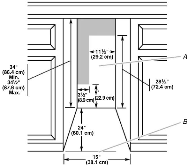
text_image
34" (86.4 cm) Min. 34½" (87.6 cm) Max. 11½" (29.2 cm) 3½" (8.9 cm) 9" (22.9 cm) 24" (60.1 cm) 15" (38.1 cm) A 28½" (72.4 cm) BA. Recommended location for electrical and plumbing fixtures
B. Floor level
- Choose a location where the floor is even. It is important for the ice maker to be level in order to work properly. If needed, you can adjust the height of the ice maker by changing the height of the leveling legs. See “Leveling.”
Electrical Requirements
WARNING

Electrical Shock Hazard
Plug into a grounded 3 prong outlet.
Do not remove ground prong.
Do not use an adapter.
Do not use an extension cord.
Failure to follow these instructions can result in death, fire, or electrical shock.
Before you move your ice maker into its final location, it is important to make sure you have the proper electrical connection:
A 115 volt, 60 Hz., AC only, 15- or 20-amp electrical supply, properly grounded in accordance with the National Electrical Code and local codes and ordinances, is required.
It is recommended that a separate circuit, serving only your ice maker, be provided. Use a receptacle which cannot be turned off by a switch or pull chain.
IMPORTANT: If this product is connected to a GFCI (Ground Fault Circuit Interrupter) equipped outlet, nuisance tripping of the power supply may occur, resulting in loss of cooling. Ice quality may be affected. If nuisance tripping has occurred, and if the condition of the ice appears poor, dispose of it.
Recommended Grounding Method
The ice maker must be grounded. The ice maker is equipped with a power supply cord having a 3 prong grounding plug. The cord must be plugged into a mating, 3 prong, grounding-type wall receptacle, grounded in accordance with the National Electrical Code and local codes and ordinances. If a mating wall receptacle is not available, it is the personal responsibility of the customer to have a properly grounded, 3 prong wall receptacle installed by a qualified electrician.
Water Supply Requirements
Check that the water supply lines are insulated against freezing conditions. Ice formations in the supply lines can increase water pressure and damage your ice maker or home. Damage from frozen supply lines is not covered by the warranty.
A cold water supply with water pressure of between 30 and 120 psi (207 and 827 kPa) is required to operate the ice maker. If you have questions about your water pressure, call a licensed, qualified plumber.
Reverse Osmosis Water Supply
IMPORTANT:
■ A reverse osmosis water filtration system is not recommended for ice makers that have a drain pump installed.
■ For gravity drain systems only.
■ The pressure of the water supply coming out of a reverse osmosis system going to the water inlet valve of the ice maker needs to be between 30 and 120 psi (207 and 827 kPa).
If a reverse osmosis water filtration system is connected to your cold water supply, the water pressure to the reverse osmosis system needs to be a minimum of 40 to 60 psi (276 to 414 kPa).
NOTE: The reverse osmosis system must provide 1 gal. (3.8 L) of water per hour to the ice maker for proper ice maker operation. If a reverse osmosis system is desired, only a whole-house capacity reverse osmosis system, capable of maintaining the steady water supply required by the ice maker, is recommended. Faucet capacity reverse osmosis systems are not able to maintain the steady water supply required by the ice maker.
If the water pressure to the reverse osmosis system is less than 40 to 60 psi (276 to 414 kPa):
■ Check to see whether the sediment filter in the reverse osmosis system is blocked. Replace the filter if necessary.
■ Allow the storage tank on the reverse osmosis system to refill after heavy usage.
If you have questions about your water pressure, call a licensed, qualified plumber.
Vacation or Extended Time Without Use
■ When you will not be using the ice maker during the summer months, turn off the water and power supply to the ice maker.
■ Check that the water supply lines are insulated against freezing conditions. Ice formations in the supply lines can increase water pressure and cause damage to your ice maker or home. Damage from freezing is not covered by the warranty.
Connect Water Supply
Read all directions before you begin.
IMPORTANT:
■ Plumbing shall be installed in accordance with the International Plumbing Code and any local codes and ordinances.
■ Use copper tubing or Whirlpool supply line, Part Number 8212547RP, and check for leaks.
■ Install tubing only in areas where temperatures will remain above freezing.
Tools Needed
Gather the required tools and parts before starting installation:
■ Flat-blade screwdriver
■ 7/16" and 1/2" open-end wrenches or two adjustable wrenches
■ 1/4" nut driver
NOTE: Do not use a piercing-type or 316 " (4.76 mm) saddle valve which reduces water flow and clogs more easily.
Connecting the Water Line
- Turn off main water supply. Turn on nearest faucet long enough to clear line of water.
- Using a 12 " copper supply line with a quarter-turn shutoff valve or the equivalent, connect the ice maker as shown.
NOTE: To allow sufficient water flow to the ice maker a minimum 12 " diameter home supply line is recommended.
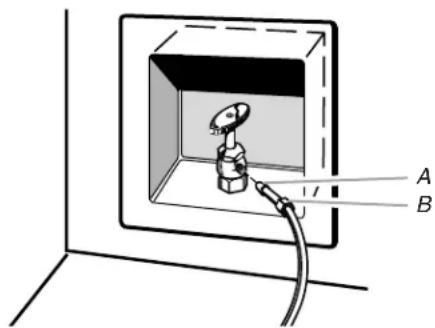
text_image
Technical diagram showing a component inside a 3D box with labeled parts A and B, and a cable or wire connection.A. Bulb
B. Nut
- Now you are ready to connect the copper tubing. Use 14 " (6.35 mm) OD soft copper tubing for the cold water supply.
■ Ensure that you have the proper length needed for the job. Be sure both ends of the copper tubing are cut square.
■ Slip compression sleeve and compression nut on copper tubing as shown. Insert end of tubing into outlet end squarely as far as it will go. Screw compression nut onto outlet end with adjustable wrench. Do not overtighten.
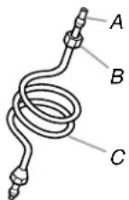
A. Compression sleeve
B. Compression nut
C. Copper tubing
- Place the free end of the tubing into a container or sink, and turn on main water supply and flush out tubing until water is clear. Turn off shutoff valve on the water pipe.
IMPORTANT: Always drain the water line before making the final connection to the inlet of the water valve to avoid possible water valve malfunction. - Bend the copper tubing to meet the water line inlet which is located on the back of the ice maker cabinet as shown. Leave a coil of copper tubing to allow the ice maker to be pulled out of the cabinet or away from the wall for service.
Rear View
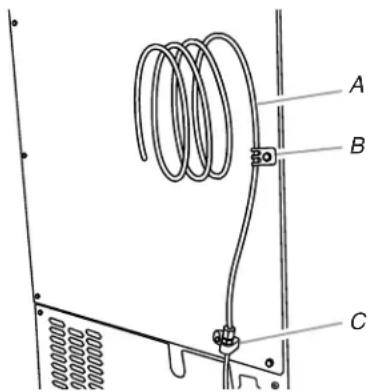
text_image
Technical diagram showing a coiled spring assembly with labeled components A, B, and CA. Copper tubing
B. Water supply tube clamp
C. Inlet water tube clamp and supply line connector
- Remove and discard the short, black plastic tube from the end of the water line inlet.
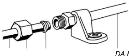
- Thread the nut onto the end of the tubing. Tighten the nut by hand. Then tighten it with a wrench two more turns. Do not overtighten.
NOTE: To avoid rattling, be sure the copper tubing does not touch the cabinet's side wall or other parts inside the cabinet.
natural_image
Technical line drawing of a mechanical assembly with two components connected by a threaded connector (no text or symbols)A. Line to ice maker
B. Nut (purchased)
C. Ferrule (purchased)
D. Supplied line from ice maker
- Install the water supply tube clamp around the water supply line to reduce strain on the coupling.
- Turn shutoff valve ON.
- Check for leaks. Tighten any connections (including connections at the valve) or nuts that leak.
Drain Pump Installation (on some models)
NOTE: Connect drain pump to your drain in accordance with all state and local codes and ordinances. It may be desirable to insulate drain tube thoroughly up to drain inlet to minimize condensation on the drain tube. Insulated tube kit Part Number W10365792 is available for purchase. Drain pump is designed to pump water to a maximum height of 10 ft (3 m). Use only Whirlpool approved drain pump kit Part Number 1901A. Do not connect the outlet end of the drain tube to a closed pipe system to keep drain water from backing up into the ice maker.
Kit Contains:
■ Drain pump kit Part Number 1901A
■ 58 " ID x 518 " drain tube (ice maker bin to drain pump reservoir inlet)
■ 12 " ID x 10 ft (3 m) drain tube hose (drain pump discharge to household drain)
■ 5/16" ID x 32" (81 cm) vent tube (drain pump reservoir vent to ice maker cabinet back)
■ Cable clamps (secures vent tube to back of ice maker) (3)
■ #8-32 x 38 " pump mounting screws (secrees drain pump to baseplate and clamps to back of ice maker) (5)
■ 58 " small adjustable hose clamp (secrees vent to drain pump)
■ 7/8" large adjustable hose clamp, (secures drain tube to ice maker bin and drain pump reservoir inlet) (3)
■ Rear panel (2)
■ Instruction sheet
If Ice Maker Is Currently Installed
NOTE: If ice maker is not installed, please proceed to "Drain Pump Installation" section.
- Push the selector switch to the Off position.
WARNING

Electrical Shock Hazard
Disconnect power before servicing.
Replace all parts and panels before operating.
Failure to do so can result in death or electrical shock.
- Unplug ice maker or disconnect power.
- Turn off water supply. Wait 5 to 10 minutes for the ice to fall into the storage bin. Remove all ice from bin.
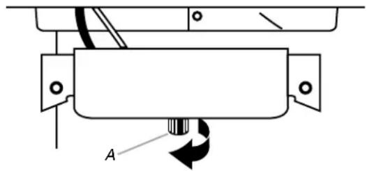
- Unscrew the drain cap from the bottom of the water pan located inside the storage bin. Allow water to drain completely. Replace drain cap. See "Drain Cap" illustration.
Drain Cap
natural_image
Pure mechanical diagram showing a rotating component with labeled point A (no text or symbols beyond label)A. Drain cap
- If ice maker is built into cabinets, pull ice maker out of the opening.
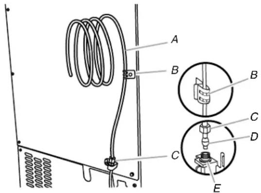
- Disconnect water supply line. See "Water Supply Line" illustration.
Water Supply Line
text_image
Technical diagram of a mechanical assembly with labeled components A through E, including coiled spring and internal components.A. 14 " copper tubing
B. Cable clamp
C. 14 " compression nut
D. Ferrule (sleeve)
E. Ice maker connection
Drain Pump Installation
NOTE: Do not kink, smash or damage tubes or wires during installation.
- Unplug ice maker or disconnect power.
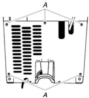
- Remove rear panel. See "Rear Panel" illustration for 5 screw locations. Pull rear panel away from the drain tube and discard.
Rear Panel
text_image
A B AA. Screw locations
- Remove the old drain tube and clamp attached to the ice maker bin.
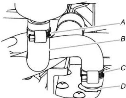
NOTE: Discard old drain tube and clamp. - Install new drain tube (5/8" ID x 51/8") from ice maker bin to drain pump reservoir inlet using new adjustable clamps. See "Drain Tube" illustration.
NOTES:
■ Do not kink.
■ Trim tube length, if required.
Drain Tube
text_image
A B C DA. 78 adjustable hose clamp
C. 7/8" adjustable hose clamp
B. Drain tube (ice bin to drain pump)
D. Drain pump reservoir inlet
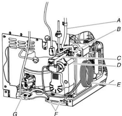
- Install vent tube ( 516 " ID x 32" [81 cm]) to drain pump reservoir vent. Use one 58 " small adjustable clamp, supplied. See "Parts Locations" illustration.
NOTE: Do not install household drain tube at this time.
Parts Locations
text_image
Technical diagram of an appliance with labeled parts A through G, showing internal components and wiring connections.A. Vent tube
E. Ice maker unit power cord
B. 5/8" hose clamp
F. #8-32 x 38 " pump mounting screws
C. Drain pump discharge tube
G. Drain pump power cord, clamp and screw
D. Drain pump
- Remove power cord clamp and ground screw attached to ice maker power cord, which is mounted to the unit base. See "Parts Locations" illustration.
NOTE: Clamp and screw will be reused.
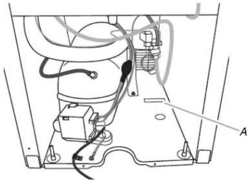
- Slide drain pump into the ice maker base on the right side. The pump mounting tab should slip into the rectangular slot in the ice maker base. It will be necessary to tip the pump slightly to slip into the slot. See "Drain Pump Mounting Tab Slot" illustration.
Drain Pump Mounting Tab Slot
natural_image
Technical diagram of an appliance showing internal components and wiring (no text or labels)A. Mounting tab slot
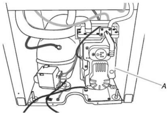
Drain Pump Installed
natural_image
Technical diagram of a mechanical assembly with labeled component A, showing internal components and wiring (no text or symbols beyond label)A. Drain pump installed
-
Align the 2 screw holes at the rear of the pump. Use two #8-32 x 38 " screws, supplied. See "Parts Locations" illustration.
-
Connect drain tube to ice maker bin outlet ( 58 " ID), using 78 " adjustable clamp, supplied. See "Drain Tube" illustration.
-
Coil ice maker power cord into a 4" (10.2 cm) diameter coil. Wrap electrical tape around the power cord in several places to keep the cord in a coil. Locate coiled power cord between the drain pump and side of enclosure and plug into the receptacle of the drain pump. See "Parts Locations" illustration.
-
Attach the drain pump power cord to ice maker unit base with clamp and screw (removed in Step 6) that was used to attach ice maker power cord. See "Parts Locations" illustration.
-
Place new rear panel (small one for 15" ice makers, large one for 18") against the back of the ice maker. Route the vent tube and drain pump discharge tube through cutouts in the rear panel.
-
Secure rear panel with original screws. See "Rear Panel" illustration.
-
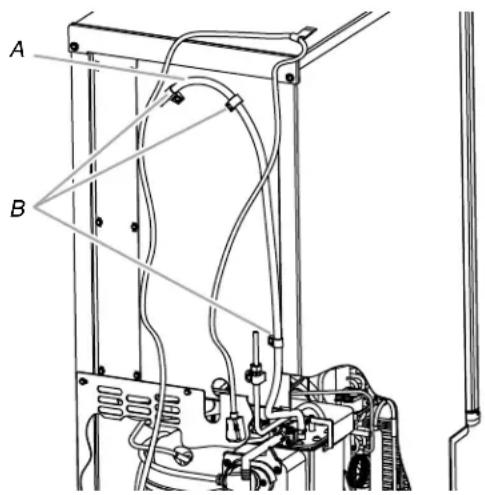
Secure vent tube to back of ice maker using 3 clamps and three #8-32 x 3 / 8 screws, supplied. See "Vent Tube" illustration.
Vent Tube
NOTE: Do not pinch, kink or damage the vent tube. Check that it is not damaged, or pinched or kinked between the cabinet and the ice maker.
text_image
Technical diagram of a mechanical device with labeled components A and B, showing wiring and components.A. Vent tube
B. Clamps and screws
- Attach 12 " ID x 10 ft (3 m) drain tube to pump discharge tube. See "Parts Locations" illustration.
- Connect ice maker to water supply and install ice maker as specified by the product installation instructions.
- Check all connections for leaks.
WARNING

Electrical Shock Hazard
Plug into a grounded 3 prong outlet.
Do not remove ground prong.
Do not use an adapter.
Do not use an extension cord.
Failure to follow these instructions can result in death, fire, or electrical shock.
- Plug in ice maker or reconnect power.
- Turn on ice maker.
- Wait for rinsing cycle, approximately 5 minutes, to be sure the ice maker is operating properly.
Drain Connection
Gravity Drain System
Connect the ice maker drain to your drain in accordance with all state and local codes and ordinances. If the ice maker is provided with a gravity drain system, follow these guidelines when installing drain lines. This will help keep water from flowing back into the ice maker storage bin and potentially flowing onto the floor, causing water damage.
- Drain lines must have a minimum of 58 (15.88 mm) inside diameter.
- Drain lines must have a 1" drop per 48" (2.54 cm drop per 122 cm) of run or 14 " drop per 12" (6.35 mm per 30.48 cm) of run and must not have low points where water can settle.
■ The floor drains must be large enough to accommodate drainage from all drains.
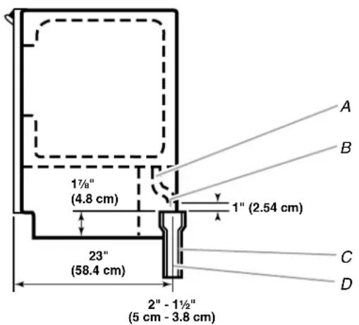
■ The ideal installation has a standpipe with a 1½" (3.81 cm) to 2" (5.08 cm) PVC drain reducer installed directly below the outlet of the drain tube as shown. You must maintain a 1" (2.54 cm) air gap between the drain hose and the standpipe.
■ Do not connect the outlet end of the drain tube to a closed pipe system to keep drain water from backing up into the ice maker.
IMPORTANT: A drain pump is necessary when a floor drain is not available. A Drain Pump kit, Part Number 1901A, is available for purchase.
Side View
text_image
17/8" (4.8 cm) 23" (58.4 cm) 1" (2.54 cm) 2" - 1½" (5 cm - 3.8 cm) A B C DA. Drain hose
B. 1" (2.54 cm) air gap
C. PVC drain reducer
D. Center of drain should be 23" (58.4 cm) from front of door, with or without the 34 " (1.91 cm) panel on the door. The drain should also be centered from left to right (7 516 " [18.56 cm] from either side of the ice maker).
Drain Pump System (on some models)
IMPORTANT:
■ Connect the ice maker drain to your drain in accordance with the International Plumbing Code and any local codes and ordinances.
■ The drain pump discharge line must terminate at an open sited drain.
■ Maximum rise 10 ft (3.1 m)
■ Maximum run 100 ft (30.5 m)
NOTES:
■ If the drain hose becomes twisted and water cannot drain, your ice maker will not work.
■ It may be desirable to insulate the drain line thoroughly up to the drain inlet. An Insulation Sleeve kit, Part Number W10365792, is available for purchase.
■ Do not connect the outlet end of the drain tube to a closed pipe system to keep drain water from backing up into the ice maker.
Connecting the Drain
After ensuring that the drain system is adequate, follow these steps to properly place the ice maker:
WARNING

Electrical Shock Hazard
Plug into a grounded 3 prong outlet.
Do not remove ground prong.
Do not use an adapter.
Do not use an extension cord.
Failure to follow these instructions can result in death, fire, or electrical shock.
- Plug into a grounded 3 prong outlet.
WARNING
Excessive Weight Hazard
Use two or more people to move and install ice maker.
Failure to do so can result in back or other injury.
- Style 1—For gravity drain system, push the ice maker into position so that the ice maker drain tube is positioned over the PVC drain reducer. See “Gravity Drain System.”
Style 2—For drain pump system connect the drain pump outlet hose to the drain. See “Drain Pump System.” - Recheck the ice maker to be sure that it is level. See "Leveling."
- If it is required by your local sanitation code, seal the cabinet to the floor with an approved caulking compound after all water and electrical connections have been made.
Door Reversal—Side Swing Only
Tools Needed
Gather the required tools and parts before starting installation.
■ 5/16" wrench
■ Flat putty knife
■ 1/4" wrench
■ Phillips screwdriver
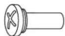
Hinge pin
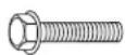
5/16" hex-head hinge screw

Handle screw End cap screw
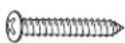
Remove Stainless Steel Door Wrap Panel—On Some Models
natural_image
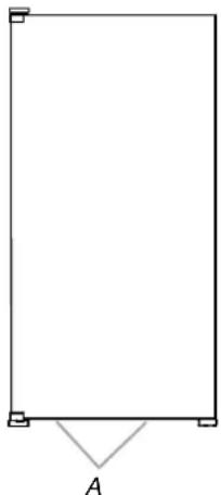
Simple geometric diagram showing a rectangle with corner markers and an angle labeled A (no text or symbols beyond the label)A. Hex-head screws
- Remove the 2 hex-head screws located under the stainless steel door wrap panel flange on the bottom of the door.
- Pull up and outward on the door wrap panel from the bottom.
- Rotate the door wrap panel until it separates from the door and pull up.
NOTE: Be sure the edge guards do not separate from the door wrap panel.
Door Stop and End-Cap Reversal
WARNING

Electrical Shock Hazard
Disconnect power before servicing.
Replace all parts and panels before operating.
Failure to do so can result in death or electrical shock.
- Unplug the ice maker or disconnect power.
- Remove the handle screws and handle (on some models).
- Remove the hinge pin from the top hinge.
- Remove the door from the hinges and replace the top hinge pin.
-
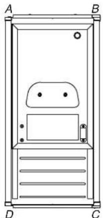
Remove the screw and door stop at corner A. Remove the screw and end cap at corner C. Place the door stop at corner C, and tighten screw. Place the end cap at corner A, and tighten screw.
-
Remove the screw and door stop at corner D. Remove the screw and end cap at corner B. Place the door stop at corner B, and tighten screw. Place the end cap at corner D, and tighten screw.
natural_image
Technical line drawing of a door or enclosure with labeled sections A, B, C, D and internal features (no text or symbols beyond labels)A. Top corner open (no end cap)
C. Beginning bottom corner end cap
B. Beginning top corner end cap
D. Bottom corner open (no end cap)
-
Depending on your model, the brand badge for the front door of your ice maker may be in the package with the Use and Care Guide. Fasten the brand badge to the door.
-
Set the door aside.
Reverse Hinges
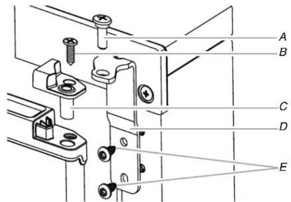
- Unscrew and remove the top hinge. Replace the screws in the empty hinge holes.
- Remove the screws from the bottom of the opposite side of the ice maker cabinet. Turn the top hinge upside down so that the hinge pin points up. Place the hinge on the bottom opposite side of the ice maker and tighten screws.
- Remove the "old" bottom hinge screws and hinge. Replace the screws in the empty hinge holes.
- Remove the screws from the top of the opposite side of the ice maker cabinet. Turn the hinge upside down so that the hinge pin points down. Place the hinge on the top opposite side of the ice maker and tighten the screws.
- Remove the top hinge pin.
Replace Door
- Place the door on the bottom hinge pin.
- Align the door with the top hinge hole and replace the top hinge pin.
- Replace the handle and handle screws.
On Some Models—Replace Door Wrap
- Place the door wrap flange onto the door top and ensure that it fits correctly.
- Rotate the door wrap downward until it covers the door surface completely.
- Install the 2 hex-head screws into the bottom of the door.
Top Hinge
text_image
Technical diagram of a mechanical assembly with labeled parts A through E, showing bolted connections and mounting features.A. Hinge pin
B. Phillips-head countersink screw
C. Hinge pin sleeve
D. Hinge
E. Hex-head hinge screw
Bottom Hinge

text_image
Technical diagram of a mechanical assembly with labeled parts A, B, C, D, and EA. Hex-head hinge screw
B. Hinge pin sleeve
C. Phillips-head countersink screw
D. Hinge pin
E. Hinge
Reverse Door Catch
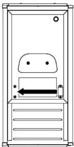
- Remove the white decorative screws from the opposite side of the door and set aside.
- Remove the screws from the magnetic door catch and replace it on the opposite side of the door.
natural_image
Simple line drawing of a door with an arrow indicating left motion (no text or symbols)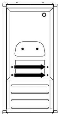
natural_image
Simple line drawing of a door with two arrows indicating flow or movement (no text or symbols)- Install the white decorative screws on the opposite side of the door.
WARNING

Electrical Shock Hazard
Plug into a grounded 3 prong outlet.
Do not remove ground prong.
Do not use an adapter.
Do not use an extension cord.
Failure to follow these instructions can result in death, fire, or electrical shock.
- Plug into a grounded 3 prong outlet.
Leveling
It is important for the ice maker to be level in order to work properly. Depending upon where you install the ice maker, you may need to make several adjustments to level it. You may also use the leveling legs to lower the height of the ice maker for undercounter installations.
Tools Needed
Gather the required tools and parts before starting installation.
■ 9" level
■ Adjustable wrench
NOTE: It is easier to adjust the leveling legs if you have another person to assist you.
- Move the ice maker to its final location.
NOTE: If this is a built-in installation, move the ice maker as close as possible to the final location.
- Place the level on top of the product to see whether the ice maker is level from front to back and side to side.
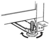
- Push up on the top front of the ice maker, and then locate the leveling screws that are on the bottom front of the ice maker.
- Using an adjustable wrench, change the height of the legs as follows:
■ Turn the leveling leg to the right to lower that side of the ice maker.
■ Turn the leveling leg to the left to raise that side of the ice maker.
NOTE: The ice maker should not wobble. Use shims to add stability when needed.
- Push up on the top rear of the ice maker and locate the leveling legs that are on the bottom rear of the ice maker.
- Follow the instructions in Step 4 to change the height of the legs.
- Use the level to recheck the ice maker to see that it is even from front to back and side to side. If the ice maker is not level, repeat steps 2 to 5. If the ice maker is level, go to the "Connect Water Supply" section.
Water Filtration System
Do not use with water that is microbiologically unsafe or of unknown quality without adequate disinfection before or after the system. Systems certified for cyst reduction may be used on disinfected waters that may contain filterable cysts.
Install the Water Filter
- Locate the accessory packet in the ice maker and remove the water filter.
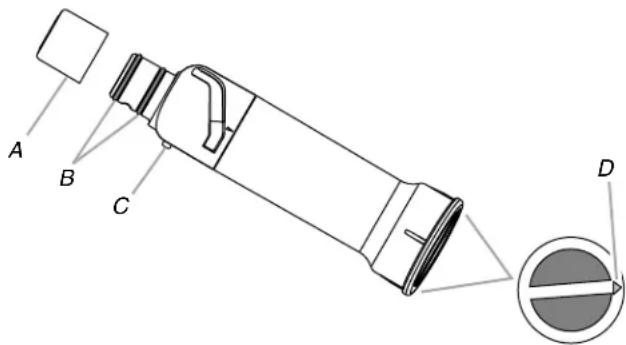
- Take the water filter out of its packaging and remove the cover from the O-rings. Be sure the O-rings are still in place after the cover is removed.
text_image
A B C DA. Cover
C. Alignment pin
B. O-rings
D. Alignment arrow
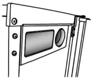
- The water filter compartment is located in the right-hand side of the ice maker controls.
natural_image
Technical line drawing of a mechanical or architectural component with numbered components (no text or symbols)- Using the arrow pointing to the alignment pin on the side of the filter and the arrow inside the control housing, align the alignment pin with the cutout notch and insert the filter into the housing.
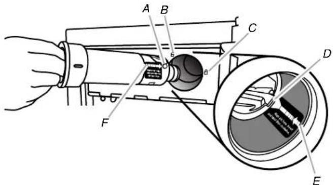
text_image
Technical diagram of a mechanical device with labeled components A through F, showing internal components and parts.A. Alignment pin
D. Cutout notch inside control housing
B. Unlocked symbol
E. Arrow pointing to cutout notch
C. Locked symbol
F. Arrow pointing to alignment pin
- Turn the filter clockwise until it locks into the housing. Ensure that the alignment arrow on the filter head aligns with the locked symbol on the control box housing.
NOTE: If the filter is not correctly locked into the housing, the ice maker will not produce ice.
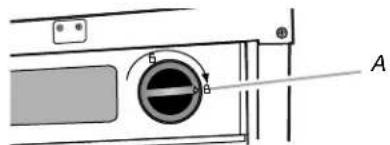
text_image
Diagram of a device with labeled components and directional arrow, marked with letter AA. Alignment arrow aligned with locked symbol
The Water Filter Status Light
The water filter status lights will help you know when to change your water filter.
■ The "Order Filter" status light will be illuminated when it is time to order a replacement filter.
■ The "Replace Filter" status light will be illuminated when it is time to replace the filter.
■ Replacing the disposable water filter with a new filter will automatically reset the filter status tracking feature. See "Using the Controls."
NOTES:
■ "Replace Filter" will remain illuminated if a filter is not installed.
■ The "Filter" status light will flash if the filter is not correctly installed or there is an obstruction in the water line.
Replace the Water Filter
To purchase a replacement water filter, see "Accessories."
Replace the disposable water filter when indicated on the water filter status display or at least every 9 months. If the ice making rate decreases before the Replace Filter light illuminates, then replace the filter.
- Locate the water filter compartment in the right-hand side of the control housing. See Step 3 in the "Install Water Filter" section.
- Turn the water filter counterclockwise (to the left), and pull it straight out of the compartment.
NOTE: There may be some water in the filter. Some spilling may occur.
- Install the replacement water filter by following steps 2 through 5 in the "Install the Water Filter" section.
ICE MAKER USE
How Your Ice Maker Works
When you first start your ice maker, the water pan will fill and the system will rinse itself before starting to make ice. The rinsing process takes about 5 minutes.
Under normal operating conditions, the ice maker will cycle at preset temperatures. The ice level sensor located in the ice storage bin will monitor the ice levels.
IMPORTANT: If the water supply to the ice maker is turned off, be sure to set the ice maker control to OFF.
The Ice Making Process
- Water is constantly circulated over a freezing plate. As the water freezes into ice, the minerals in the water are rejected. This produces a sheet of ice with a low mineral content.
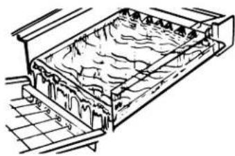
natural_image
Technical line drawing of a rectangular container with internal structure and grid pattern (no text or symbols)- When the desired thickness is reached, the ice sheet is released and slides onto a cutter grid. The grid divides the sheet into individual cubes.
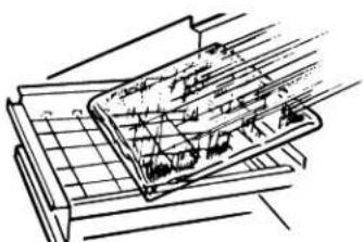
natural_image
Technical line drawing of a mechanical assembly with grid and rod (no text or symbols)- The water containing the rejected minerals is drained after each freezing cycle.
-
Fresh water enters the machine for the next ice making cycle.
-
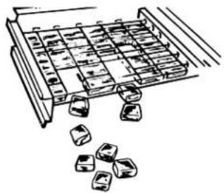
Cubes fall into the storage bin. When the bin is full, the ice maker shuts off automatically and restarts when more ice is needed. The ice bin is not refrigerated, and some melting will occur. The amount of melting varies with room temperature.
natural_image
Illustration of a tray with ice cubes and scattered ice cubes (no text or symbols)NOTE: As the room and water temperatures vary, so will the amount of ice produced and stored. This means that higher operating temperatures result in reduced ice production.
Using the Controls
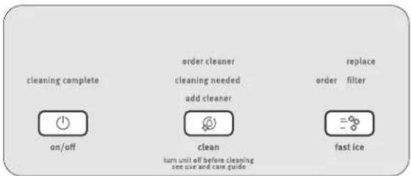
- To start ice production, press ON/OFF.
- To stop ice maker operation, press ON/OFF.
text_image
cleaning complete on/off order cleaner cleaning needed add cleaner clean turn unit off before cleaning see use and care guide replace order filter fast iceNOTES:
■ Pressing the On/Off button does not shut off power to the ice maker.
■ Allow 24 hours to produce the first batch of ice. Discard the first 2 batches produced.
Fast Ice Mode
Select the Fast Ice feature when you have an upcoming need for a large amount of ice and the ice bin is low or empty. Fast Ice mode will produce a greater quantity of ice in a 24-hour period.
■ Press FAST ICE while the ice maker is on. The indicator light will illuminate.
■ Press FAST ICE again to turn off the Fast Ice feature. The indicator light will turn off.
■ The Fast Ice mode will be on when you first turn on the product. It will turn off after 24 hours. To turn Fast Ice back on, press FAST ICE.
Clean
It is recommended that you clean the ice maker when the "Cleaning Needed" light is illuminated or 9 months has elapsed or ice production decreases significantly. To clean your ice maker, see "Ice Maker System" in the "Cleaning" section.
Door Ajar Alarm
The Door Ajar Alarm feature sounds an alarm when the ice maker door is open for 5 minutes. The alarm will repeat every 2 minutes. Close the door to turn off. The feature then resets and will reactivate when the door is left open again for 5 minutes.
Normal Sounds
Your new ice maker may make sounds that are not familiar to you. Because the sounds are new to you, you might be concerned about them. Most of the new sounds are normal. Hard surfaces such as floors, walls and cabinets can make the sounds seem louder than they actually are. The following describes the kinds of sounds that might be new to you and what may be making them.
■ You will hear a buzzing sound when the water valve opens to fill the water pan for each cycle.
■Rattling noises may come from the flow of the refrigerant or the water line. Items stored on top of the ice maker can also make noises.
■ The high-efficiency compressor may make a pulsating or high pitched sound.
■ Water running over the evaporator plate may make a splashing sound.
■ Water running from the evaporator plate to the water pan may make a splashing sound.
■ As each cycle ends, you may hear a gurgling sound due to the refrigerant flowing in your ice maker.
■ You may hear air being forced over the condenser by the condenser fan.
■ During the harvest cycle, you may hear a "thud" when the ice sheet slides from the evaporator onto the cutter grid.
■ When you first start the ice maker, you may hear water running continuously. The ice maker is programmed to run a rinse cycle before it begins to make ice.
■ If the ice maker is connected to a water supply pressure in excess of 60 psi, you may hear a loud sound during water filling associated with the flow of water through the inlet valve. Call a licensed, qualified plumber to determine the best method to reduce the supply water pressure (50 psi is recommended).
ICE MAKER CARE
Cleaning
The ice making system and the air cooled condenser need to be cleaned regularly for the ice maker to operate at peak efficiency and to avoid premature failure of system components. See the "Ice Maker System" and the "Condenser" sections.
Exterior Surfaces
Wash the exterior enamel surfaces and gaskets with warm water and mild soap or detergent. Wipe and dry. Regular use of a good household appliance cleaner and wax will help maintain the finish. Do not use abrasive cleaners on enamel surfaces as they may scratch the finish.
For products with a stainless steel exterior, use a clean sponge or soft cloth and a mild detergent in warm water. Do not use abrasive or harsh cleaners. Do not use chlorine bleach on the stainless steel surfaces.
Ice Maker System
Minerals that are removed from water during the freezing cycle will eventually form a hard scaly deposit in the water system. Cleaning the system regularly helps remove the mineral scale buildup. How often you need to clean the system depends upon how hard your water is. With hard water of 15 to 20 grains/gal. (4 to 5 grains/liter), you may need to clean the system as often as every 9 months.
NOTE: Use one 16 oz (473 mL) bottle of approved ice maker cleaner. To order, see "Accessories."
- Press the ON/OFF button.
- Wait 5 to 10 minutes for the ice to fall into the storage bin. Remove all ice from the storage bin.
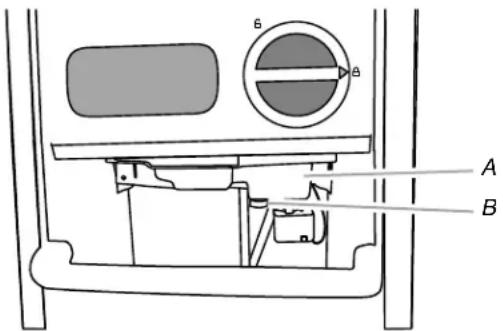
- Unscrew the drain cap from the bottom of the water pan located inside the storage bin as shown. Allow the water to drain completely.
- Replace the drain cap securely on the water pan. If the drain cap is loose, water will empty from the water pan and you will have either thin ice or no ice.
- Read and follow all handling information on the cleaner bottle before completing the steps below. Use one 16 oz (473 mL) bottle of approved ice maker cleaner.
- Pour one bottle of solution into the water pan. Fill the bottle twice with tap water and pour it into the water pan.
text_image
A BA. Water pan
B. Drain cap
- Press the CLEAN button. See "Using the Controls." The Clean button will blink, indicating that the cleaning cycle is in process. When the "Cleaning Complete" light is illuminated (approximately 70 minutes), the cleaning cycle is complete. During the cleaning cycle, the system will both clean and rinse itself.
- After the cleaning cycle is complete, remove the drain cap from the water pan. Look for any cleaning solution left in the water pan. If cleaning solution drains from the water pan, you should run the clean cycle again. Be sure to refill the water pan with cleaner before starting the clean cycle again. Be sure to replace the drain cap securely on the water pan. If the drain cap is loose, water will empty from the water pan and you will have either thin ice or no ice.
NOTE: Severe scale buildup may require repeated cleaning with a fresh quantity of cleaning solution.
- Press the ON/OFF button to resume ice production.
Condenser
A Dirty or Clogged Condenser
■ Obstructs proper airflow.
■ Reduces ice making capacity.
■ Causes higher than recommended operating temperatures which may lead to component failure.
WARNING

Electrical Shock Hazard
Disconnect power before cleaning.
Replace all parts and panels before operating.
Failure to do so can result in death or electrical shock.
- Unplug ice maker or disconnect power.
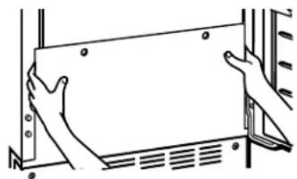
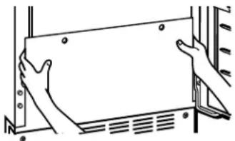
- Remove the 2 screws in the lower access panel and the 2 screws from the base grille area of the front panel support.
- Pull the bottom forward and then pull down to remove the lower access panel.
natural_image
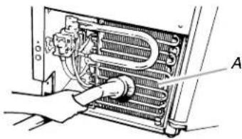
Line drawing of hands holding a rectangular panel or frame (no text or symbols)- Remove dirt and lint from the condenser fins and the unit compartment with a brush attachment on a vacuum cleaner.
natural_image
Diagram of a hand inserting a component into a device panel (no text or symbols visible)A. Condenser fins
-
Replace the lower access panel using the 4 screws.
-
Plug in ice maker or reconnect power.
Interior Components
- Unplug ice maker or disconnect power.
- Open the storage bin door and remove any ice that is in the bin.
- Remove the drain cap from the water pan and drain thoroughly. Replace the drain cap securely on the water pan. If the drain cap is loose, water will empty from the water pan, and you will have either thin ice or no ice.
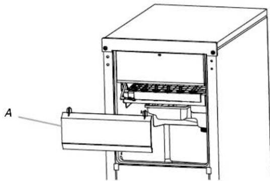
- Pull out on the bottom of the cutter grid cover until the snaps release to remove.
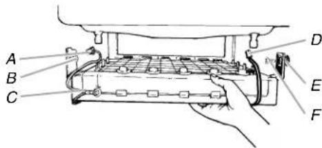
- Unplug the wiring harness from the left side of the cutter grid.
natural_image
Technical line drawing of a mechanical device with labeled component A (no text or symbols beyond label)A. Cutter grid cover
- Unplug the ice level sensor from the right side of the cutter grid. Pull the ice level sensor down and forward away from the cutter grid.
- Remove the right-hand and left-hand screws. Lift the cutter grid up and out.
NOTE: Make sure the plastic spacer from the right-hand side of the cutter grid bracket stays with the cutter grid.
text_image
A B C D E FA. Cutter grid harness
B. Screw
C. Cutter grid
D. Ice level sensor harness
E. Plastic spacer
F.Screw
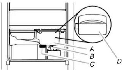
- Remove the mounting screw that holds the water pan in place. Pull out on the front of the water pan.
- Disconnect the pump bracket from the water pan and unplug the water pan drain pump.
text_image
A B C DA. Water pan
B. Water pan screw
C. Drain cap
D. Drain pump cover
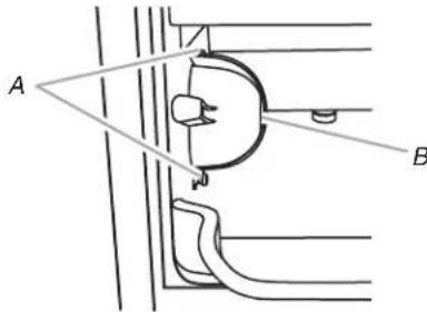
- Remove, clean and replace the ice scoop and ice scoop holder.
NOTE: On some models, the ice scoop holder is located in the upper left of the unit, and on other models, the ice scoop holder is located in the lower left of the unit.
■ After removing the ice scoop, remove the holder by removing the 2 screws.
■ Wash the ice scoop holder along with the other interior components using the following instructions.
■ Replace the ice scoop holder by replacing the screws.
text_image
A BA. Screw
B. Ice scoop holder
- Wash the interior components (cutter grid, exterior of hoses, and water pan) and the storage bin, door gasket, ice scoop, and ice scoop holder with mild soap or detergent and warm water. Rinse in clean water. Then clean the same parts with a solution of 1 tbs (15 mL) of household bleach in 1 gal. (3.8 L) warm water. Rinse again thoroughly in clean water.
NOTE: Do not remove hoses. Do not wash plastic parts in dishwasher. They cannot withstand temperatures above 145^ F ( 63^ C).
-
To replace the water pan, set the water pan inside the ice bin. Hook up the water pan pump. Snap the pump bracket back onto the water pan and place back into position. Secure the water pan by replacing the mounting screw.
-
Check the following:
-
Drain cap from the water pan is securely in place. If the drain cap is loose, water will empty from the water pan, and you will have either thin ice or no ice.
■ Hose from water pan is inserted into storage bin drain opening. -
Slide the cutter grid back into place and secure it by replacing the right-hand screw and plastic spacer. Then tighten the left-hand screw. Reconnect the cutter grid harness and the ice level sensor harness.
-
Replace the cutter grid cover.
- Gently wipe the control panel with a soft, clean dishcloth using warm water and a mild liquid dish detergent.
- Plug in ice maker or reconnect power.
- After cleaning, make sure that all controls are set properly and that no control indicators are flashing.
Vacation and Moving Care
WARNING

Electrical Shock Hazard
Disconnect power before servicing.
Replace all parts and panels before operating.
Failure to do so can result in death or electrical shock.
To Shut Down the Ice Maker:
- Unplug ice maker or disconnect power.
- Remove all ice from storage bin.
- Shut off the water supply.
-
Remove the 2 screws in the lower access panel and the 2 screws from the base grille area of the front panel support. Pull forward to remove the lower access panel.
-
Disconnect the inlet and outlet lines to water valve. Allow these lines to drain and then reconnect to the valve.
- Replace lower access panel and screws.
- Drain water from water pan by removing the drain cap.
- If the room temperature will drop below 32^ F ( 0^ C), water must be removed from the drain line.
For Ice Makers with a Drain Pump Installed:
■ Plug in ice maker or reconnect power.
■ Turn ice maker off and remove all remaining ice from ice bin.
■ Pour 1 qt (0.95 L) of water into the ice bin near the drain and let the ice maker stand for approximately 5 minutes. This will allow the water in the bin to drain into the drain pump so that the pump will remove the remaining water from the ice bin and the drain pump.
■ Unplug ice maker or disconnect power.
-
Before using again, clean the ice maker and storage bin.
-
Plug into a grounded 3 prong outlet.
NOTE: All components of the ice maker are permanently lubricated at the factory. They should not require any additional oiling throughout the normal life of the machine.
natural_image
Line drawing of hands holding a rectangular panel or frame, no text or symbols presentTROUBLESHOOTING
First try the solutions suggested here or visit our website and reference FAQs
(Frequently Asked Questions) to possibly avoid the cost of a service call.
In the U.S.A., www.maytag.com In Canada, www.maytag.ca
Ice Maker Operation
WARNING

Electrical Shock Hazard
Plug into a grounded 3 prong outlet.
Do not remove ground prong.
Do not use an adapter.
Do not use an extension cord.
Failure to follow these instructions can result in death, fire, or electrical shock.
PROBLEM RECOMMENDED SOLUTIONS
| Ice Maker Will Not Operate | Check that it is plugged into a grounded 3 prong outlet.Check that the control is turned on. See “Using the Controls.”Replace the fuse or reset the circuit breaker.NOTE:If problems continue, contact an electrician.Room temperature must be above 55°F (13°C). Otherwise, bin thermostat may sense cold room temperature and shut off even though the bin is not full of ice. The ice maker may not restart once it does shut off.If there was a large amount of water added to the ice maker, wait a few minutes for the drain pump to clear. If there is still water in the bin, check to see whether the drain hose is kinked.For models with drain pumps, check that the drain hose is not damaged, or kinked or pinched between cabinet and ice maker. Use only Whirlpool approved drain pump kit, Part Number 1901A. |
| Ice Maker Seems Noisy | Is the water in the reservoir overflowing? This is normal. This overflow helps to purge minerals that were removed from the water during the ice making process.Is there a “whooshing” sound? Check the following things:■ Check that the water supply is hooked up and turned on.■ Check that the drain cap is tight and the water drain pan pump is securely attached to the water pan.Is there ice between the evaporator plate and the cutting grid? Check that the ice maker is level. See “Leveling.” If the ice maker is level, and the problem persists, run a cleaning cycle. See “Cleaning.”If the ice maker is connected to a water supply pressure in excess of 60 psi, you may hear a loud sound during water filling associated with the flow of water through the inlet valve. Call a licensed, qualified plumber to determine the best method to reduce the supply water pressure (50 psi is recommended). |
Ice Production
WARNING

Electrical Shock Hazard
Disconnect power before servicing.
Replace all parts and panels before operating.
Failure to do so can result in death or electrical shock.
PROBLEM RECOMMENDED SOLUTIONS
| Ice Maker Runs But Produces No Ice | Check that the control is turned on.Check that the water supply is properly connected and turned on.If the drain cap is loose, water will empty from the water pan, and you will have either thin ice or no ice. Tighten the drain cap.Clean the drain tube.Check that there are no kinks in the drain line. |
| Ice Maker Runs But Produces Very Little Ice | Is the accelerated ice production feature turned on? This feature increases the ice production rate to provide you with more ice in the same amount of time. See “Using the Controls.”Room temperatures of more than 90°F (32°C) will normally reduce ice production.Dirt or lint may be blocking the airflow through the condenser. See “Condenser” in the “Cleaning” section.If there is white scale buildup in the ice maker’s water or freezing system, you should clean the ice maker. See “Interior Components” in the “Cleaning” section.If the drain cap is loose, water will empty from the water pan, and you will have either thin ice or no ice. Tighten the drain cap.Ensure that the cutter grid is securely in place and that its harness plug is connected. See “Interior Components” section of “Cleaning” for instructions on cutter grid removal.Check that water filter is properly installed. |
Ice Quality
PROBLEM RECOMMENDED SOLUTIONS
| Off Taste, Odor or Gray Color in the Ice | Is there unusually high mineral content in the water supply? The water may need to be treated.Is there mineral scale buildup? Clean your ice maker. See “Ice Maker System” in the “Cleaning” section.Do not store any foods in the ice bin.Check that all packaging materials were removed at the time of installation. |
| Thin, Soft or Clumps of Ice | Is there unusually high mineral content in the water supply? The water may need to be treated.Is there mineral scale buildup? Clean your ice maker. See “Ice Maker System” in the “Cleaning” section.Are there clumps of ice in the bin? If ice is not used regularly, it will melt and form clumps. Break the clumps with the ice scoop provided. |
Plumbing Problems
WARNING
Excessive Weight Hazard
Use two or more people to move and install ice maker.
Failure to do so can result in back or other injury.
PROBLEM RECOMMENDED SOLUTIONS
| Water Not Entering Drain Properly | Is the drain hose aligned over the drain? Move the ice maker to align the drain. See “Connect Water Supply.”NOTE: Service technicians cannot repair plumbing problems outside of the ice maker. Call a licensed, qualified plumber. |
Accessories
To order accessories, in the U.S.A., visit our web site www.maytag.com/accessories or call 1-800-901-2042.
In Canada, visit our web site www.whirlpoolparts.ca or call 1-800-807-6777.
Water Filter
Order Part Number F2WC9I1or ICE2
Cleaner
Order Part Number 4396808
affresh ^® \* Stainless Steel Cleaner
In U.S.A., order Part Number W10355016
In Canada, order Part Number W10355016B
affresh ^® \* Stainless Steel Wipes
In U.S.A., order Part Number W10355049
In Canada, order Part Number W10355049B
affresh ^® \* Kitchen & Appliance Cleaner
In U.S.A., order Part Number W10355010
In Canada, order Part Number W10355010B
*affresh is a trademark of Whirlpool, U.S.A.
PERFORMANCE DATA SHEET
Ice Maker Water Filtration System
Model P6GEG2KL, P6KG2KL, P6WG2KL Capacity 2000 Gallons (7571 Liters)

System tested and certified by NSF International against NSF/ANSI Standard 42 for the reduction of Chlorine Taste and Odor.
This system has been tested according to NSF/ANSI Standards 42 for the reduction of the substances listed below. The concentration of the indicated substances in water entering the system was reduced to a concentration less than or equal to the permissible limit for water leaving the system, as specified in NSF/ANSI Standards 42.
| Substance Reduction Aesthetic Effects | NSF Reduction Requirements | Average Influent | Influent Challenge Concentration | Maximum Effluent | Average Effluent | Minimum % Reduction | Average % Reduction |
| Chlorine Taste/Odor 50 | % reduction 1.9 | 27 mg/L 2.0 | mg/L ± 10% 0.71 mg/L | 0.7788 mg/L | 70.2 72.81 |
Test Parameters: pH = 7.5 ± 0.5 unless otherwise noted. Flow = 0.50 gpm (1.89 Lpm). Pressure = 60 psig (413.7 kPa). Temp. = 68°F to 71.6°F (20°C to 22°C). Rated service capacity = 2000 gallons (7571 liters).
■ It is essential that operational, maintenance, and filter replacement requirements be carried out for the product to perform as advertised.
■ Use replacement filter P6RFWG2K, P6RFGEG2K, P6RFKG2K, Part Number ICE2.
Style 1 - When the water filter status display changes from "GOOD" to "ORDER," order a new filter. When the filter indicator reads "REPLACE," it is recommended that you replace the filter.
Style 2 – Press FILTER to check the status of your water filter. If the filter indicator light is yellow and the words “ORDER FILTER” appear on the display screen, order a new filter. If the filter indicator light is red, it is recommended that you replace the filter.
■ These contaminants are not necessarily in your water supply. While testing was performed under standard laboratory conditions, actual performance may vary.
■ The product is for cold water use only.
■ Do not use with water that is microbiologically unsafe or of unknown quality without adequate disinfection before or after the system.
■ Refer to the "Warranty" section for the Manufacturer's name, address and telephone number.
■ Refer to the "Warranty" section for the Manufacturer's limited warranty.
| Application Guidelines/Water Supply Parameters | |
| Water Supply | City or Well |
| Water Pressure | 30 - 120 psi (207 - 827 kPa) |
| Water Temperature | 33° - 100°F (0.6° - 37.8°C) |
| Service Flow Rate | 0.50 gpm (1.89 Lpm) @ 60 psi |
natural_image
Technical line drawing of a cylindrical mechanical component with internal channels and mounting flanges (no text or symbols)MAYTAG® MAJOR APPLIANCE WARRANTY
LIMITED WARRANTY
For one year from the date of purchase, when this major appliance is operated and maintained according to instructions attached to or furnished with the product, Maytag brand of Whirlpool Corporation or Whirlpool Canada LP (hereafter “Maytag”) will pay for factory specified parts and repair labor to correct defects in materials or workmanship. Service must be provided by a Maytag designated service company. This limited warranty is valid only in the United States or Canada and applies only when the major appliance is used in the country in which it was purchased. Outside the 50 United States and Canada, this limited warranty does not apply. Proof of original purchase date is required to obtain service under this limited warranty.
ITEMS EXCLUDED FROM WARRANTY
This limited warranty does not cover:
- Service calls to correct the installation of your major appliance, to instruct you on how to use your major appliance, to replace or repair house fuses, or to correct house wiring or plumbing.
- Service calls to repair or replace appliance light bulbs, air filters or water filters. Consumable parts are excluded from warranty coverage.
- Repairs when your major appliance is used for other than normal, single-family household use or when it is used in a manner that is contrary to published user or operator instructions and/or installation instructions.
- Damage resulting from accident, alteration, misuse, abuse, fire, flood, acts of God, improper installation, installation not in accordance with electrical or plumbing codes, or use of consumables or cleaning products not approved by Maytag.
- Cosmetic damage, including scratches, dents, chips or other damage to the finish of your major appliance, unless such damage results from defects in materials or workmanship and is reported to Maytag within 30 days from the date of purchase.
- Any food loss due to refrigerator or freezer product failures.
- Costs associated with the removal from your home of your major appliance for repairs. This major appliance is designed to be repaired in the home and only in-home service is covered by this warranty.
- Repairs to parts or systems resulting from unauthorized modifications made to the appliance.
- Expenses for travel and transportation for product service if your major appliance is located in a remote area where service by an authorized Maytag servicer is not available.
- The removal and reinstallation of your major appliance if it is installed in an inaccessible location or is not installed in accordance with published installation instructions.
- Major appliances with original model/serial numbers that have been removed, altered or cannot be easily determined. This warranty is void if the factory applied serial number has been altered or removed from your major appliance.
The cost of repair or replacement under these excluded circumstances shall be borne by the customer.
DISCLAIMER OF IMPLIED WARRANTIES; LIMITATION OF REMEDIES
CUSTOMER'S SOLE AND EXCLUSIVE REMEDY UNDER THIS LIMITED WARRANTY SHALL BE PRODUCT REPAIR AS PROVIDED HEREIN. IMPLIED WARRANTIES, INCLUDING WARRANTIES OF MERCHANTABILITY OR FITNESS FOR A PARTICULAR PURPOSE, ARE LIMITED TO ONE YEAR OR THE SHORTEST PERIOD ALLOWED BY LAW. MAYTAG SHALL NOT BE LIABLE FOR INCIDENTAL OR CONSEQUENTIAL DAMAGES. SOME STATES AND PROVINCES DO NOT ALLOW THE EXCLUSION OR LIMITATION OF INCIDENTAL OR CONSEQUENTIAL DAMAGES, OR LIMITATIONS ON THE DURATION OF IMPLIED WARRANTIES OF MERCHANTABILITY OR FITNESS, SO THESE EXCLUSIONS OR LIMITATIONS MAY NOT APPLY TO YOU. THIS WARRANTY GIVES YOU SPECIFIC LEGAL RIGHTS, AND YOU MAY ALSO HAVE OTHER RIGHTS WHICH VARY FROM STATE TO STATE OR PROVINCE TO PROVINCE.
If outside the 50 United States and Canada, contact your authorized Maytag dealer to determine if another warranty applies.
10/12
For additional product information, in the U.S.A., visit www.maytag.com
In Canada, visit www.maytag.ca
If you do not have access to the Internet and you need assistance using your product or you would like to schedule service, you may contact Maytag at the number below.
Have your complete model number ready. You can find your model number and serial number on the label, located on the inside wall of the ice maker compartment.
For assistance or service in the U.S.A., call 1-800-688-9900. In Canada, call 1-800-807-6777.
If you need further assistance, you can write to Maytag with any questions or concerns at the address below:
In the U.S.A.:
Maytag Brand Home Appliances
Customer eXperience Center
553 Benson Road
Benton Harbor, MI 49022-2692
In Canada:
Maytag Brand Home Appliances
Customer eXperience Centre
200 - 6750 Century Ave.
Mississauga, Ontario L5N 0B7
Please include a daytime phone number in your correspondence.
Please keep this User Instructions and model number information for future reference.
text_image
Technical diagram showing a component inside a rectangular housing with labeled points A and B, likely illustrating a mechanical or electrical assembly.A. Bulbo B. Tuerca
text_image
Technical diagram showing a coiled spring assembly with labeled components A, B, and Cnatural_image
Technical line drawing of a mechanical assembly with two connectors and a bracket (no text or symbols)natural_image
Mechanical assembly diagram showing a rotating component with labeled point A (no text or symbols beyond label)A. Tapa de desagüe
text_image
Technical diagram of a mechanical assembly with labeled components A through E, including coiled spring and internal components.text_image
Technical diagram of an appliance with labeled components A through G, showing internal wiring and housing layout.natural_image
Technical diagram of an appliance showing internal components and wiring (no text or labels)natural_image
Technical diagram of a mechanical assembly with labeled component A (no text or symbols beyond label)text_image
Technical diagram of a mechanical device with labeled components A and B, showing wiring and components in a assembly.natural_image
Simple geometric diagram showing a rectangle with corner markers and an angle labeled A (no text or symbols beyond the label)natural_image
Technical line drawing of a cabinet or enclosure with labeled sections A, B, C, D and internal components (no text or symbols beyond labels)text_image
Technical diagram of a mechanical assembly with labeled parts A through E, showing bolted connections and alignment lines.text_image
Technical diagram of a mechanical assembly with labeled parts A, B, C, D, and Enatural_image
Technical line drawing of a door with an arrow indicating left motion (no text or symbols)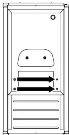
natural_image
Simple line drawing of a door with two arrows indicating flow or movement (no text or symbols)natural_image
Technical line drawing of a mechanical or architectural component with mounting holes and a central screen (no text or symbols)text_image
Technical diagram of a mechanical device with labeled components A through F, showing internal components and parts.natural_image
Diagram of a door handle mechanism with labeled component A (no text or symbols beyond label)natural_image
Technical line drawing of a rectangular container with internal layered structure (no text or symbols)natural_image
Technical line drawing of a mechanical assembly or processing device with grid lines and no visible text or symbolsnatural_image
Illustration of a tray with stacked blocks and scattered ice cubes (no text or symbols)text_image
cleaning complete on/off order cleaner cleaning needed add cleaner clean turn unit off before cleaning see use and care guide replace order filter fast iceNOTAS:
text_image
Technical diagram of a vehicle air intake system with labeled components A and Bnatural_image
Line drawing of hands holding a rectangular panel with mounting holes (no text or symbols)natural_image
Diagram of a hand inserting a component into a device panel (no text or symbols visible)natural_image
Technical line drawing of a mechanical device with labeled component A (no text or symbols beyond label)natural_image
Line drawing of hands holding a rectangular panel with mounting holes (no text or symbols)natural_image
Technical line drawing of a cylindrical mechanical component with threaded ends and internal channels (no text or symbols)GARANTÍA DE LOS ELECTRODOMÉSTICOS PRINCIPALES DE MAYTAG®
GARANTÍA LIMITADA
Customer eXperience Centre
200-6750 Century Ave.
Mississauga, Ontario L5N 0B7
text_image
Technical diagram showing a mechanical component inside a rectangular enclosure with labeled points A and Btext_image
Technical diagram showing a coiled spring assembly with labeled components A, B, and Cnatural_image
Technical line drawing of a mechanical assembly with threaded connector and mounting bracket (no text or symbols)text_image
Technical diagram of a mechanical assembly with labeled components A through E, including coiled spring and internal components.text_image
Technical diagram of a mechanical component with labeled parts A, B, C, and DA. Bride de tuyau réglable de 7/8"
C. Bride de tuyau réglable de 7/8"
text_image
Technical diagram of an appliance with labeled components A through G, showing internal wiring and housing layout.A. Tube de ventilation
natural_image
Technical diagram of an appliance internal structure with labeled component A (no text or symbols beyond label)natural_image
Technical diagram of a mechanical assembly with labeled component A, showing internal components and wiring (no text or symbols beyond label)A. Pompe de vidange installée
text_image
Technical diagram of a mechanical device with labeled components A and B, showing wiring and connections.A. Tube de ventilation
B. Brides et vis
natural_image
Simple geometric diagram showing a rectangle with corner markers and an angle labeled A (no text or symbols beyond the label)natural_image
Technical line drawing of a cabinet or enclosure with labeled corners A, B, C, D and internal compartments (no text or symbols beyond labels)text_image
Technical diagram of a mechanical assembly with labeled parts A through E, showing bolted connections and mounting brackets.text_image
Technical diagram of a mechanical assembly with labeled parts A, B, C, D, and Enatural_image
Simple line drawing of a door with an arrow indicating left motion (no text or symbols)