UXT5236ADQ - Range hood MAYTAG - Free user manual and instructions
Find the device manual for free UXT5236ADQ MAYTAG in PDF.



| Brand | Maytag |
| Model | UXT5236ADQ |
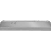
| Product Type | Under-Cabinet Range Hood |
| Width | 91.4 cm (36 in) |
| Depth | 25.4 cm (10 in) |
| Height | 15.2 cm (6 in) |
| Power Supply | 120 V, 60 Hz, 15-20 A, dedicated circuit |
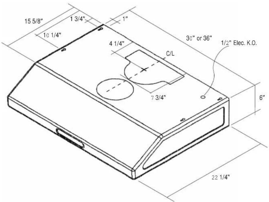
| Venting Modes | Vertical venting (round 6 in or rectangular 3 1/4 x 10 in) or horizontal rear venting (3 1/4 x 10 in); convertible for recirculation |
| Recommended Mounting Height | Between 61 cm (24 in) and 81.3 cm (32 in) above the range |
| Filters | Washable metal filters; optional charcoal filters (ref. HCFLTUXT36, 3 per set) |
| Metal Filter Maintenance | Regular cleaning in dishwasher or by hand |
| Charcoal Filter Replacement | Every 120 hours of use (approximately 2-3 months) |
| Installation | Must be installed by a qualified professional; requires rigid metal ductwork |
| Material | Stainless steel |
| Warranty | Consult the manual for details |
| Country of Manufacture | Not specified |
Frequently Asked Questions - UXT5236ADQ MAYTAG
User questions about UXT5236ADQ MAYTAG
0 question about this device. Answer the ones you know or ask your own.
Ask a new question about this device
Download the instructions for your Range hood in PDF format for free! Find your manual UXT5236ADQ - MAYTAG and take your electronic device back in hand. On this page are published all the documents necessary for the use of your device. UXT5236ADQ by MAYTAG.
USER MANUAL UXT5236ADQ MAYTAG
Safety Instructions....1
Mounting Heights.... 2
Ducting....3-7-9
Specifications....4
Installation....5-6
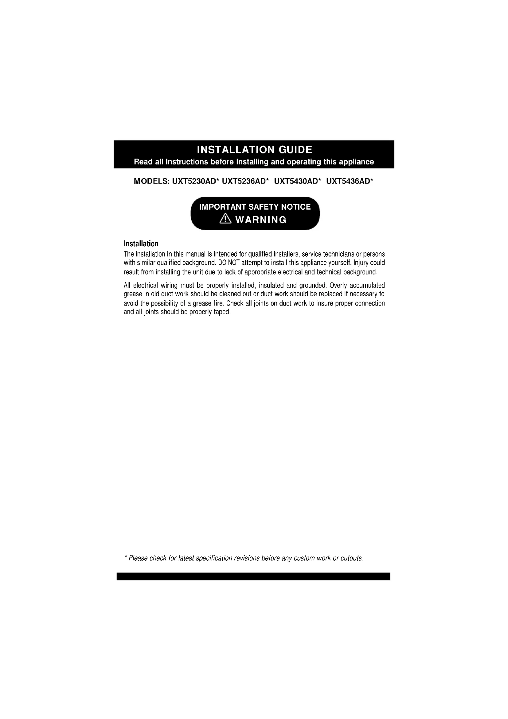
INSTALLATION GUIDE
Read all Instructions before Installing and operating this appliance
MODELS: UXT5230AD* UXT5236AD* UXT5430AD* UXT5436AD*
IMPORTANT SAFETY NOTICE
WARNING
Installation
The installation in this manual is intended for qualified installers, service technicians or persons with similar qualified background. DO NOT attempt to install this appliance yourself. Injury could result from installing the unit due to lack of appropriate electrical and technical background.
All electrical wiring must be properly installed, insulated and grounded. Overly accumulated grease in old duct work should be cleaned out or duct work should be replaced if necessary to avoid the possibility of a grease fire. Check all joints on duct work to insure proper connection and all joints should be properly taped.
INSTALLATION
MOUNTING HEIGHTS
DUCTING
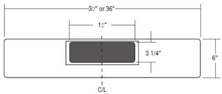
A minimum of 6" round or 3-1/4"x10" rectangular duct must be used to maintain maximum air flow efficiency.
Always use rigid-type metal ducts only.
Flexible ducts could restrict air flow by up to 50%.
Also use calculation (on right) to compute total available duct run when using elbows, transitions and caps.
ALWAYS, when possible, reduce the number of transitions and turns. If long duct run is required, increase duct size from 6" to 7 or 8". If a reducer is used, install a long reducer instead of a pancake reducer. Reduce duct size as far away from opening as possible.
If turns or transitions are required:
Install as far away from opening and as far apart, between 2, as possible.
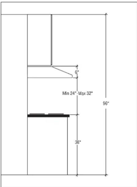
Minimum mounting height between range top to hood bottom should be no less than 24".
Maximum mounting height should be no higher than 32".
It is important to install the hood at the proper mounting height. Hoods mounted too low could result in heat damage and fire hazard; while hoods mounted too high will be hard to reach and will lose performance and efficiency.
If available, also refer to range manufacturer's height clearance requirements and recommended hood mounting height above range.
*Minimum clearance of 24" hood above range height.
** Maximum clearance 32" hood above range height.
Minimum Duct Size:
Round:
6" minimum
Rectangular:
3-1/4"x10"
Duct Run Calculation:
Maximum run
| 6" or 3-1/4" x 10" duct | 100 FT |
| Deduct: | |
| each 90 Elbow used | 15 FT |
| each 45 elbow used | 9 FT |
| each 6" to 3/14 x 10" transition used | 1 FT |
| each 3/14 x 10" to 6" | |
| each 3/14 x 10" to 6" transition used | 5 FT |
| Side Wall Cap w/ damper | 30 FT |
| Roof Cap | 30 FT |
e.g.- 1 roof cap, 2x90 elbows, 1 45 elbow used:
= 30^ + 30^ + 9^ = 69^ used, 31^ available for straight duct runs.
INSTALLATION
DUCTING

WARNING FIRE HAZARD
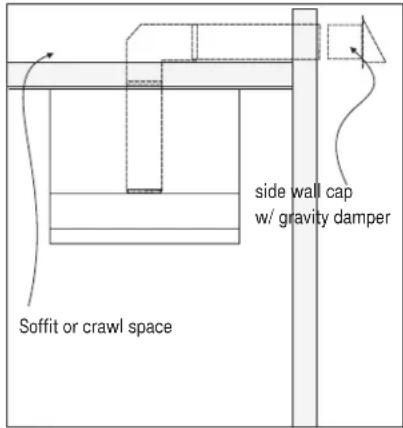
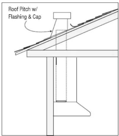
NEVER exhaust air or terminate duct work into spaces between walls, crawl spaces, ceiling, attics or garages. All exhaust must be ducted to the outside.
Use Metal ductwork only.
Fasten all connections with sheet metal screws and tape all joints w/ certified Silver Tape or DuctTape.
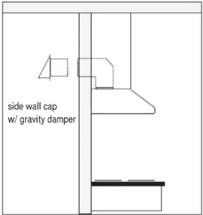
Some Ducting Options:
INSTALLATION
SPECIFICATIONS
INSTALLATION
MOUNTING THE RANGEHOOD
ELECTRICAL

WARNING
All Electrical work must be performed by qualified electrician or person with similar technical know how and background.
For personal safety, remove house fuse or open circuit breaker before beginning installation.
Do not use extension cord or adapter plug with this appliance.
Follow National electrical codes or prevailing local codes and ordinances.
Electrical Supply:
This appliance requires a 120V 60Hz electrical supply, connected to an individual, properly grounded branch circuit, protected by a 15 or 20 ampere circuit breaker or time delay fuse. Wiring must be 2 wire w/ ground. Please also refer Electrical Diagram labeled on product.
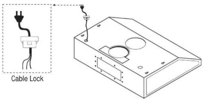
Cable Lock:
A cable locking connector (not supplied) might also required by local codes. Check with local requirements and codes, purchase and install appropriate connector if necessary.
INSTALLATION
MOUNTING THE RANGEHOOD
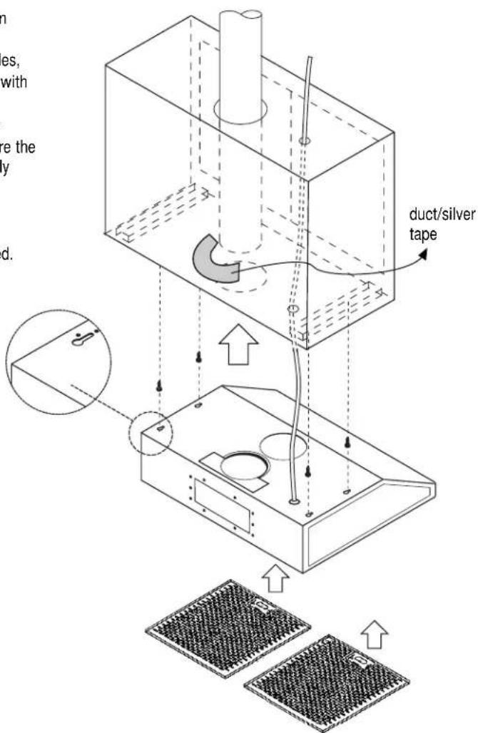
- This range hood is mounted under a kitchen cabinet unit.
- Select preferred duct location on rear or top of unit. For ductless conversion, no ducting is required.
- Begin installation by temporarily removing the diffuser and filter panels.
- Temporarily position the range hood in the desired mounting location. Measure and mark the mounting holes, duct and electrical access locations with a pencil.
- Drill/cut out the required openings for duct and electrical access; make sure the duct opening is large enough to apply duct tape.
- Fasten mounting screws onto cabinet as marked, do not tighten, leaving half length of screws exposed.
- Install electrical.
- Hang hood onto screws through key holes, and tighten.
- Install duct work and duct-tape.
- Reinstall the difuser panels.
- Power up hood and check for leaks around duct-tape.
INSTALLATION
7
CONVERTIBLE OPTIONS
This range hood is equipped with the option of a 6" vertical discharge, 3 1/4"x10" vertical discharge, or 3 1/4"x10" rear discharge. Additional accessories are provided to convert to either of the above discharge methods.
Convertible Options
| Vertical discharge | 6" round |
| Vertical discharge | 3 1/4"x10" |
| Horizontal rear discharge | 3 1/4"x10" |
Convertible Accessories
| Round to rectangular transition adaptor |
| Rectangular to round transition adaptor (pre-mounted) |
| Gasket (pre-mounted) |
| Rectangular rear cap (pre-mounted) |
| 3 1/4"x10" starting collar |
3 1/4"x10" Vertical Discharge
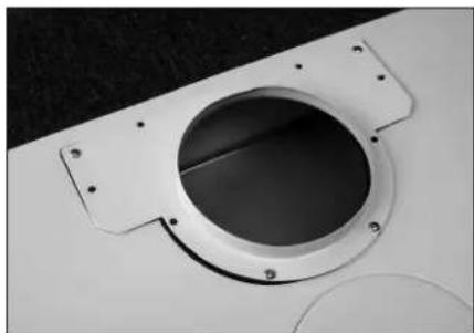
natural_image
Close-up of a white mechanical component with a circular opening and mounting flanges (no text or symbols visible)- Remove pre-mounted 6" transition adaptor or duct opening. Leave attached gasket in its original place.
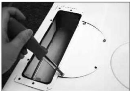
natural_image
Close-up of a hand using a tool to cut or mark a component on a white surface, with no visible text or symbols.- Place rectangular transition adaptor as shown over gasket and by first installing 4 screws on half round section.
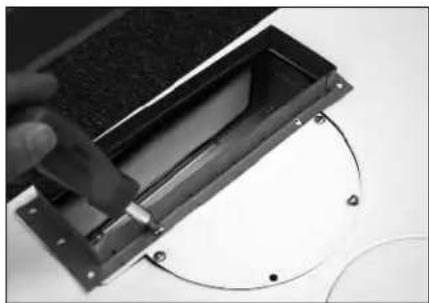
natural_image
Close-up of a hand using a tool to insert or install a black electronic component, with circular components visible (no text or symbols)- Mount the 3-1/4"x10" starting collar on top of transition piece with remaining screws.
INSTALLATION
CONVERTIBLE OPTIONS
3 1/4"x10" Rear Discharge
natural_image
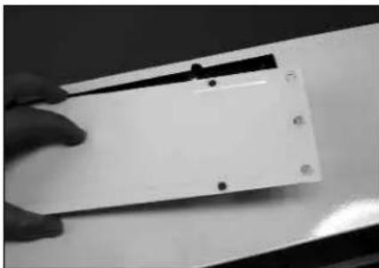
Close-up of a hand holding a white plastic sheet with four small holes, against a plain background (no text or symbols visible)- At rear of range hood, remove all screws on pre-mounted rear rectangular cap and remove cap.
natural_image
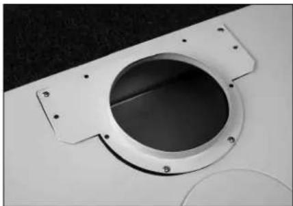
Close-up of a white mechanical component with a circular opening and flange, mounted on a dark surface (no text or symbols visible)- Remove top pre-mounted transition piece. Leave attached gasket in its original place.
natural_image
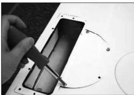
Close-up of a hand using a tool to cut a black rectangular object on a white surface, with curved lines and dots indicating motion or alignment (no text or symbols visible)- Mount rectangular transition piece at opening with gasket as shown.
natural_image
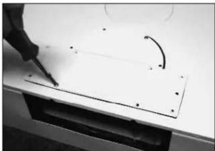
Close-up of a screwdriver inserted into a white electronic device with a rectangular panel and mounting holes (no visible text or symbols)- Mount rectangular cap (previously removed) on top of transition adaptor.
natural_image
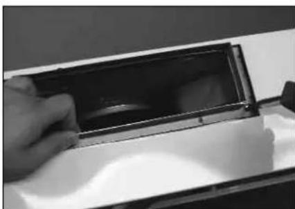
Close-up of a hand holding a small object over a dark rectangular panel (no visible text or symbols)- Mount starting collar (provided) at rear discharge opening with gasket.
INSTALLATION
DUCTLESS CONVERSION
Ductless conversion is intended for applications where an exhaust duct work is not possible to be installed. When converted, the hood functions as a "purifying" hood rather than an exhaust hood. Fumes and exhaust from cooking are drawn and filtered by a set of optional Carbon Filters. The air is then purified and re-circulated back within the home.
We recommend to ALWAYS exhaust air outside of the home by employing existing or installing new duct work, if possible. The hood is most effective and efficient as an Exhaust unit. Only when the exhaust option is not possible should you recourse to converting the hood into a "purifying"unit.
When converted to be a "purifying" unit, a Carbon Filters Kit is required. Order according to its Part number below. The standard Metal Filters are intended to capture residue from cooking and the optional Carbon Filters help to purify fumes exhausted from cooking for re-circulation.
Carbon Filters (Required)
- Purchase ductless Carbon Filters Kit as follow:
Hood Model: Part No. Filters in pkg.
UXT5230AD* HCFLTUXT30 2 UXT5236AD* HCFLTUXT36 3
UXT5430AD* HCFLTUXT30 2 UXT5436AD* HCFLTUXT36 3
- The ductless conversion housing must be installed prior to installation of the range hood.
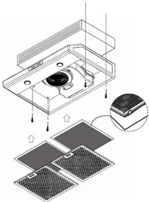
- Remove the diffuser panels on the hood.
- Clip carbon filter onto bracket of diffuser panels.
- Re-install diffuser panels.
- Carbon Filters must be replaced after every 120 hours of use (or approximately every 2 to 3 months based on the average of 1-2hrs. of daily cooking time).
- Refer installation manual provided with ductless carbon filters kit.
HOTTE DE CUISINIÈRE
Canalisation....3-7-9
INSTALLATION
MONTAGE DE LA HOTTE DE CUISINIÈRE
ÉLECTRICITÉ
AVERTISSEMENT

AVERTISSEMENT
OPTIONS TRANSFORMABLES
natural_image
Close-up of a white mechanical component with a circular opening and mounting flanges (no text or symbols visible)natural_image
Close-up of a hand using a tool to cut or mark a component on a white surface, with no visible text or symbols.natural_image
Close-up of a hand using a tool to adjust or install a black electronic component with a circular arc (no visible text or symbols)OPTIONS TRANSFORMABLES
natural_image
Close-up of a hand holding a white plastic sheet with four small holes, no visible text or symbolsnatural_image
Close-up of a white circular mechanical component with mounting flanges and central hole, mounted on a dark surface (no text or symbols visible)natural_image
Close-up of a hand using a tool to cut a rectangular electronic component with circular markings (no visible text or symbols)natural_image
Close-up of a sewing machine needle inserted into a white plastic sheet, with no visible text or symbolsnatural_image
Close-up of a hand opening a rectangular electronic device (no visible text or symbols)CAMPANA DE COCINA
Número de Modelo: UXT5230AD* UXT5430AD*
UXT5236AD* UXT5436AD*
INSTALACION
MONTANDO LA CAMPANA DE COCINA
INSTALACION
ELECTRICA

ADVERTENCIA
natural_image
Close-up of a white mechanical component with a circular opening and mounting flanges (no text or symbols visible)natural_image
Close-up of a hand using a tool to cut or repair a component, with no visible text or symbols.natural_image
Close-up of a hand using a tool to adjust or install a black electronic component with a circular arc (no visible text or symbols)natural_image
Close-up of a hand holding a white plastic sheet with four small holes, no visible text or symbolsnatural_image
Close-up of a white circular mechanical component with mounting flanges and central hole, mounted on a dark surface (no text or symbols visible)natural_image
Close-up of a hand using a tool to cut or mark a curved line on a white surface, with no visible text or symbols.natural_image
Close-up of a sewing machine needle inserted into a white plastic sheet, with no visible text or symbolsnatural_image
Close-up of a hand holding a rectangular object with a dark interior, possibly a device or container (no visible text or symbols)
- INSTALLATION GUIDE
- IMPORTANT SAFETY NOTICE
- WARNING
- Installation
- MOUNTING HEIGHTS
- DUCTING
- WARNING FIRE HAZARD
- Some Ducting Options:
- SPECIFICATIONS
- MOUNTING THE RANGEHOOD
- ELECTRICAL
- CONVERTIBLE OPTIONS
- 1/4"x10" Vertical Discharge
- 1/4"x10" Rear Discharge
- DUCTLESS CONVERSION
- Carbon Filters (Required)
- HOTTE DE CUISINIÈRE
- MONTAGE DE LA HOTTE DE CUISINIÈRE
- AVERTISSEMENT
- OPTIONS TRANSFORMABLES
- CAMPANA DE COCINA
- INSTALACION
- MONTANDO LA CAMPANA DE COCINA
- ADVERTENCIA
Brand : MAYTAG
Model : UXT5236ADQ
Category : Range hood