
MGD6630MBK - Tumble dryer MAYTAG - Free user manual and instructions
Find the device manual for free MGD6630MBK MAYTAG in PDF.

| Product Type | Gas Dryer |
| Brand | Maytag |
| Model | MGD6630MBK |
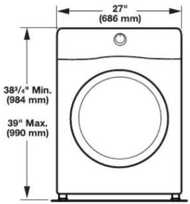
| Dimensions (W x H x D) | 27" x 38.75" (min) - 39" (max) x approx. 30" (686 x 984-990 x 762 mm) |
| Weight | 200 lb (90.7 kg) |
| Power Supply | Natural gas or propane (with conversion kit), 120 V AC, 60 Hz, 15 A |
| Drum Capacity | Approx. 7.0 cu ft (not specified, estimate) |
| Venting | 4 in (102 mm) rigid or flexible metal duct to outside |
| Maximum Duct Length | 64 ft (19.5 m) with 0 elbows, 54 ft (16.5 m) with 1 elbow (rigid duct) |
| Drying Programs | Automatic with moisture sensing, timed, adjustable temperature, steam option (depending on model) |
| Steam Function | Available on steam models (water supply hose required) |
| Noise Level | Not specified |
| Energy Class | Not specified |
| Safety | Automatic shut-off at end of cycle, lint detection, door lock |
| Maintenance | Clean lint filter after each cycle, clean exhaust duct periodically |
| Included Accessories | 4 leveling feet |
| Required Parts (not included) | Exhaust duct, hose clamps, gas shut-off valve, water supply hose (steam) |
| Door Reversal | Possible (round or square door) |
| Warranty | Not specified |
Frequently Asked Questions - MGD6630MBK MAYTAG
User questions about MGD6630MBK MAYTAG
0 question about this device. Answer the ones you know or ask your own.
Ask a new question about this device
Download the instructions for your Tumble dryer in PDF format for free! Find your manual MGD6630MBK - MAYTAG and take your electronic device back in hand. On this page are published all the documents necessary for the use of your device. MGD6630MBK by MAYTAG.
USER MANUAL MGD6630MBK MAYTAG
DRYER INSTALLATION INSTRUCTIONS
INSTRUCTIONS POUR L'INSTALLATION
DE LA SÉCHEUSE
Table of Contents Table des matières
DRYER SAFETY 2
INSTALLATION REQUIREMENTS......4
Tools and Parts....4
LOCATION REQUIREMENTS....5
ELECTRICAL REQUIREMENTS - U.S.A. ONLY....7
ELECTRIC DRYER POWER HOOKUP - CANADA ONLY ..... 8
Power Supply Cord Connection....11
4-Wire Power Supply Cord Connection....12
MAKE GAS CONNECTION....17
VENTING....18
Venting Requirements....18
Plan Vent System 19
Install Vent System....20
CONNECT INLET HOSE 21
CONNECT VENT 22
LEVEL DRYER....23
COMPLETE INSTALLATION CHECKLIST.... 23
DOOR REVERSAL (OPTIONAL)....24
SÉCURITÉ DE LA SÉCHEUSE....30
EXIGENCES D'INSTALLATION 32
RACCORDEMENT AU GAZ....39
ÉVACUATION 40
Exigences concernant l'évacuation....40
RACCORDEMENT DU CONDUIT D'ÉVACUATION .... 44
RÉGLAGE DE L'APLOMB DE LA SÉCHEUSE .... 45
ACHEVER L'INSTALLATION LISTE DE VÉRIFICATION.....45
INVERSION DE LA PORTE (FACULTATIF)......46
Date of installation:
Installer:
Model number:
Serial number:
NOTES CONCERNANT L'INSTALLATION
Date d'achat:
Your safety and the safety of others are very important.
We have provided many important safety messages in this manual and on your appliance. Always read and obey all safety messages.

This is the safety alert symbol.
This symbol alerts you to potential hazards that can kill or hurt you and others.
All safety messages will follow the safety alert symbol and either the word "DANGER" or "WARNING."
These words mean:
! DANGER
You can be killed or seriously injured if you don't immediately follow instructions.
WARNING
You can be killed or seriously injured if you don't follow instructions.
All safety messages will tell you what the potential hazard is, tell you how to reduce the chance of injury, and tell you what can happen if the instructions are not followed.

WARNING - "Risk of Fire"
- Clothes dryer installation must be performed by a qualified installer.
- Install the clothes dryer according to the manufacturer's instructions and local codes.
- Do not install a clothes dryer with flexible plastic venting materials or flexible metal (foil type) duct. If flexible metal duct is installed, it must be of a specific type identified by the appliance manufacturer as suitable for use with clothes dryers. Flexible venting materials are known to collapse, be easily crushed, and trap lint. These conditions will obstruct clothes dryer airflow and increase the risk of fire.
- To reduce the risk of severe injury or death, follow all installation instructions.
- Save these instructions.

WARNING
Fire Hazard
Failure to follow safety warnings exactly could result in serious injury, death, or property damage.
Do not install a booster fan in the exhaust duct.
Install all clothes dryers in accordance with the installation instructions of the manufacturer of the dryer.

ARNING:
FIRE OR EXPLOSION HAZARD
Failure to follow safety warnings exactly could result in serious injury, death or property damage.
- Do not store or use gasoline or other flammable vapors and liquids in the vicinity of this or any other appliance.
-
WHAT TO DO IF YOU SMELL GAS:
-
Do not try to light any appliance.
- Do not touch any electrical switch; do not use any phone in your building.
- Clear the room, building, or area of all occupants.
- Immediately call your gas supplier from a neighbor's phone. Follow the gas supplier's instructions.
- If you cannot reach your gas supplier, call the fire department.
-Installation and service must be performed by a qualified installer, service agency, or the gas supplier.
WARNING: Gas leaks cannot always be detected by smell.
Gas suppliers recommend that you use a gas detector approved by UL or CSA.
For more information, contact your gas supplier.
If a gas leak is detected, follow the "What to do if you smell gas" instructions.
IMPORTANT: The gas installation must conform with local codes, or in the absence of local codes, with the National Fuel Gas Code, ANSI Z223.1/NFPA 54, or the Natural Gas and Propane Installation Code, CSA B149.1.
The dryer must be electrically grounded in accordance with local codes, or in the absence of local codes, with the National Electrical Code, ANSI/NFPA 70, or the Canadian Electrical Code, Part 1, CSA C22.1.
In the State of Massachusetts, the following installation instructions apply:
■ Installations and repairs must be performed by a qualified or licensed contractor, plumber, or gas fitter qualified or licensed by the State of Massachusetts.
■ Acceptable Shut-off Devices: Gas Cocks and Ball Valves installed for use shall be listed.
■ A flexible gas connector, when used, must not exceed 4 feet (121.9 cm).
IMPORTANT SAFETY INSTRUCTIONS
When discarding or storing your old clothes dryer, remove the door.
SAVE THESE INSTRUCTIONS
INSTALLATION REQUIREMENTS Tools and Parts
Gather the required tools and parts before starting installation. Tools needed for all installations:
natural_image
Simple line drawing of a screwdriver (no text or symbols)Flat-blade screwdriver
natural_image
Simple line drawing of a screwdriver (no text or symbols)2 Phillips screwdriver
natural_image
Simple line drawing of a screwdriver with a handle and screw head (no text or symbols)1/4" (6 mm) and 5/16" (8 mm) nut driver (recommended)

Level
natural_image
Simple line drawing of a tape measure (no text or symbols)Tape measure
natural_image
Line drawing of a pair of pliers (no text or symbols)Pliers
natural_image
Line drawing of a flat tool with a handle and central slot (no text or symbols)Utility knife
natural_image
Line drawing of a pair of pliers (no text or symbols)Tin snips (new vent installations)
natural_image
Two types of hand tools: a cylindrical tool and a manual tool (no text or symbols)Caulking gun and compound (new vent installations)
natural_image
Line drawing of an adjustable wrench (no text or symbols)Adjustable wrench that opens to 1" (25 mm) or hex-head socket wrench
natural_image
Line drawing of a pair of pliers with no text or symbolsWire stripper (direct wire installations)
Tools needed for gas installations:
natural_image
Line drawing of an adjustable wrench (no text or symbols)8" (203 mm) or 10" (254 mm) pipe wrench
natural_image
Line drawing of an adjustable wrench (no text or symbols)8" (203 mm) or 10" (254 mm) adjustable wrench (for gas connections)
natural_image
Simple line drawing of a jar with a lid and handle (no text or symbols)Pipe-joint compound resistant to propane gas
Parts supplied (all models):
natural_image
Illustration of three threaded fasteners with hexagonal bases (no text or symbols)Leveling legs (4)
Parts needed (steam models):
natural_image
Simple line drawing of a T-shaped pipe fitting with two flanged ends (no text or symbols)"Y" connector
natural_image
Pure electrical circuit lines without any symbols2' (0.6 m) inlet hose
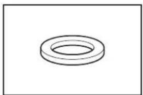
natural_image
Simple line drawing of a ring-shaped object (no text or symbols)Rubber washer
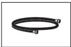
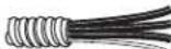
natural_image
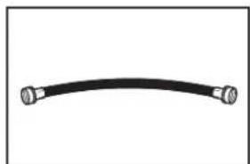
Coiled black hose with two connectors, no text or symbols visible5' (1.52 m) inlet hose
Parts package is located in dryer drum. Check that all parts are included.
NOTE: Do not use leveling legs supplied with dryer if installing with a pedestal or a stack kit.
Parts needed (not supplied with dryer):
■ent clamps
■ent elbows and vent work
Additional parts may be required, depending on your installation. Check local codes. Check existing electrical supply and venting. Read "Electrical Requirements" and "Venting Requirements" before purchasing parts.
If using a power supply cord:
Use a UL Listed power supply cord kit marked for use with clothes dryers. The kit should contain:
■ UL Listed 30 A power supply cord, rated 120/240 V minimum. The cord should be type SRD or SRDT and be at least 4 ft. (1.22 m) long. The wires that connect to the dryer must end in ring terminals or spade terminals with upturned ends.
■ UL Listed strain relief.
Optional Equipment (not supplied with dryer):
Refer to your Use and Care Guide for information about accessories available for your dryer.
LOCATION REQUIREMENTS
Check code requirements. Some codes limit, or do not permit, installing dryer in garages, closets, mobile homes, or sleeping quarters. Contact your local building inspector.
WARNING
Explosion Hazard
Keep flammable materials and vapors, such as gasoline, away from dryer.
Place dryer at least 18 inches (460 mm) above the floor for a garage installation.
Failure to do so can result in death, explosion, or fire.
You will need:
■ location allowing for proper exhaust installation. See "Venting Requirements."
■ separate 15 or 20 A circuit for a gas dryer or 30 A circuit for an electric dryer.
■ using power supply cord, a grounded electrical outlet located within 2 ft. (610 mm) of either side of dryer. See "Electrical Requirements."
■loor must support dryer weight of 200 lbs. (90.7 kg). Also consider weight of companion appliance.
Bold water faucets located within 4 ft. (1.2 m) of the water fill valves, and water pressure of 20–120 psi (138–827 kPa). You may use your washer's water supply by purchasing the necessary parts noted in "Parts needed."
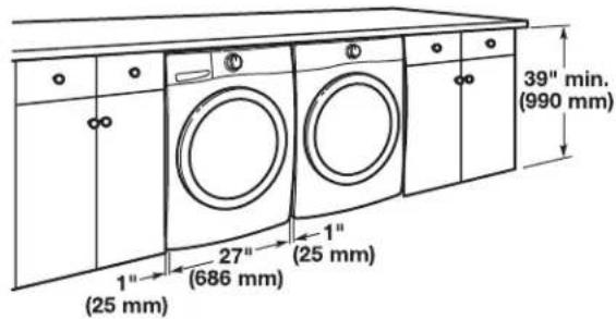
■level floor with maximum slope of 1" (25 mm) under entire dryer. If slope is greater than 1" (25 mm), install Extended Dryer Feet Kit, Part Number 279810. If not level, clothes may not tumble properly and automatic sensor cycles may not operate correctly.
■or garage installation, place dryer at least 18" (460 mm) above floor. If using a pedestal, you will need 18" (460 mm) to bottom of dryer.
■he dryer must not be installed or stored in an area where it will be exposed to water and/or weather.
IMPORTANT: Do not operate, install, or store dryer where it will be exposed to water, weather, or at temperatures below 40°F (4°C). Lower temperatures may cause dryer not to shut off at end of automatic sensor cycles, resulting in longer drying times.
DRYER DIMENSIONS
Front view:
Side view:
Whirlpool®, Amana, and Inglis Models
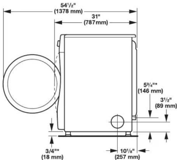
*Approx. measurement
Maytag ^® Models
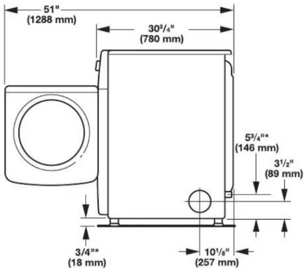
*Approx. measurement
Back view:
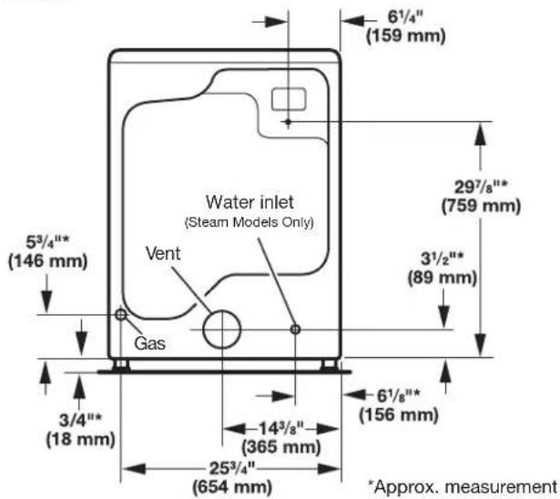
NOTE: Most installations require a minimum of 5" (127 mm) clearance behind dryer for exhaust vent with elbow. See "Venting Requirements."
Installation Clearances
For each arrangement, consider allowing more space for ease of installation and servicing, spacing for companion appliances, and clearances for walls, doors, and floor moldings. Space must be large enough to allow door to fully open. Add spacing on all sides of dryer to reduce noise transfer. If a closet door or louvered door is installed, top and bottom air openings in door are required.
Check code requirements. Some codes limit, or do not permit, installation of the dryer in garages, closets, mobile homes, or sleeping quarters. Contact your local building inspector.
NOTE: No other fuel-burning appliance can be installed in the same closet as a dryer.
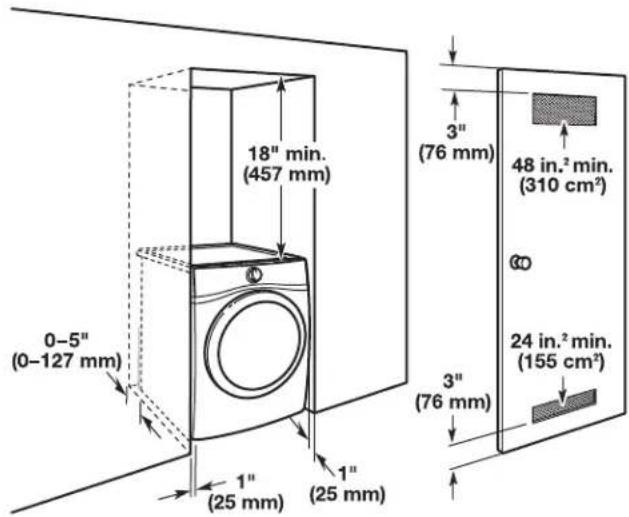
Installation spacing for recessed area or closet installation
All dimensions show recommended and minimum spacing allowed.
■additional spacing should be considered for ease of installation and servicing.
■additional clearances might be required for wall, door, floor moldings, dryer venting, and gas line.
■additional spacing should be considered on all sides of the dryer to reduce noise transfer.
■or closet installation with a door, minimum ventilation openings in the top and bottom of the door are required. Louvered doors with equivalent ventilation openings are acceptable.
■ companion appliance spacing should also be considered.
Recommended installation clearances (dryer only):
0" (0 mm) rear spacing is allowed for straight back venting only. For steam models only, inlet hose must not be kinked.
Custom under-counter installation:
Mobile home – Additional installation requirements:
This dryer is suitable for mobile home installations. The installation must conform to the Manufactured Home Construction and Safety Standard, Title 24 CFR, Part 3280 (formerly the Federal Standard for Mobile home construction and Safety, Title 24, HUD Part 280) or Standard CAN/CSA-Z240 MH.
Mobile home installations require:
Metal exhaust system hardware, available for purchase from your dealer. For further information, see "Assistance or Service" in your Use and Care Guide.
■ special provisions must be made in mobile homes to introduce outside air into dryer. Openings (such as a nearby window) should be at least twice as large as dryer exhaust opening.
For mobile home installation of gas dryers:
Mobile Home Installation Hold-down Kit Part Number 346764 is available to order. For further information, see "Assistance or Service" in your Use and Care Guide.
ELECTRICAL REQUIREMENTS - U.S.A. ONLY
It is your responsibility:
■o contact a qualified electrical installer.
■o be sure that the electrical connection is adequate and in conformance with the National Electrical Code, ANSI/NFPA 70 – latest edition and all local codes and ordinances.
The National Electrical Code requires a 4-wire power supply connection for homes built after 1996, dryer circuits involved in remodeling after 1996, and all mobile home installations.
A copy of the above code standards can be obtained from: National Fire Protection Association, One Batterymarch Park, Quincy, MA 02269.
☐o supply the required 3 or 4 wire, single-phase, 120/240 V, 60 Hz, AC-only electrical supply (or 3 or 4 wire, 120/208 V electrical supply, if specified on the serial/rating plate) on a separate 30 A circuit, fused on both sides of the line. Connect to an individual branch circuit. Do not have a fuse in the neutral or grounding circuit.
■o not use an extension cord.
■ codes permit and a separate ground wire is used, it is recommended that a qualified electrician determine that the ground path is adequate.
Electrical Connection
To properly install your dryer, you must determine the type of electrical connection you will be using and follow the instructions provided for it here.
■his dryer is manufactured ready to install with a 3-wire electrical supply connection. The neutral ground conductor is permanently connected to the neutral conductor (white wire) within the dryer. If the dryer is installed with a 4-wire electrical supply connection, the neutral ground conductor must be removed from the external ground connector (green screw), and secured under the neutral terminal (center or white wire) of the terminal block. When the neutral ground conductor is secured under the neutral terminal (center or white wire) of the terminal block, the dryer cabinet is isolated from the neutral conductor. The green ground wire of the 4-wire power cord must be secured to the dryer cabinet with the green ground screw.
■ local codes do not permit the connection of a neutral ground wire to the neutral wire, see "Optional External Ground for 3-Wire Connection" in the "Power Supply Cord Connection" section.
■ 4-wire power supply connection must be used when the appliance is installed in a location where grounding through the neutral conductor is prohibited. Grounding through the neutral is prohibited for (1) new branch-circuit installations after 1996, (2) mobile homes, (3) recreational vehicles, and (4) areas where local codes prohibit grounding through the neutral conductors.
If using a power supply cord:
Use a UL Listed power supply cord kit marked for use with clothes dryers. The kit should contain:
■ UL Listed 30 A power supply cord, rated 120/240 V minimum. The cord should be type SRD or SRDT and be at least 4 ft. (1.22 m) long. The wires that connect to the dryer must end in ring terminals or spade terminals with upturned ends.
■ UL Listed strain relief.
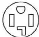
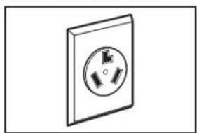
If your outlet looks like this:
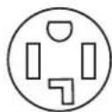
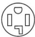
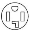
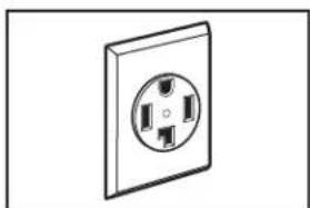
4-wire receptacle (14-30R)
Then choose a 4-wire power supply cord with ring or spade terminals and UL Listed strain relief. The 4-wire power supply cord, at least 4 ft. (1.22 m) long, must have four 10-gauge copper wires and match a 4-wire receptacle of NEMA Type 14-30R. The ground wire (ground conductor) may be either green or bare. The neutral conductor must be identified by a white cover.
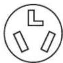
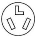
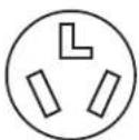
3-wire receptacle (10-30R)
Then choose a 3-wire power supply cord with ring or spade terminals and UL listed strain relief. The 3-wire power supply cord, at least 4 ft. (1.22 m) long, must have three 10-gauge copper wires and match a 3-wire receptacle of NEMA Type 10-30R.
If connecting by direct wire:
Power supply cable must match power supply (4-wire or 3-wire) and be:
■flexible armored cable or nonmetallic sheathed copper cable (with ground wire), covered with flexible metallic conduit. All current-carrying wires must be insulated.
■0-gauge solid copper wire (do not use aluminum) at least 5 ft. (1.52 m) long.
GROUNDING INSTRUCTIONS
■ For a grounded, cord-connected dryer:
This dryer must be grounded. In the event of malfunction or breakdown, grounding will reduce the risk of electric shock by providing a path of least resistance for electric current. This dryer uses a cord having an equipment-grounding conductor and a grounding plug. The plug must be plugged into an appropriate outlet that is properly installed and grounded in accordance with all local codes and ordinances.
■ For a permanently connected dryer:
This dryer must be connected to a grounded metal, permanent wiring system, or an equipment-grounding conductor must be run with the circuit conductors and connected to the equipment-grounding terminal or lead on the dryer.
WARNING: Improper connection of the equipment-grounding conductor can result in a risk of electric shock. Check with a qualified electrician or service representative or personnel if you are in doubt as to whether the dryer is properly grounded. Do not modify the plug on the power supply cord: if it will not fit the outlet, have a proper outlet installed by a qualified electrician.
SAVE THESE INSTRUCTIONS
ELECTRIC DRYER POWER HOOKUP - CANADA ONLY
ELECTRICAL REQUIREMENTS
WARNING
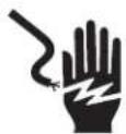
Electrical Shock Hazard
Plug into a grounded 4 prong outlet.
Failure to do so can result in death or electrical shock.
It is your responsibility:
■o contact a qualified electrical installer.
■o be sure that the electrical connection is adequate and in conformance with Canadian Electrical Code, C22.1 – latest edition and all local codes. A copy of above codes standard may be obtained from: Canadian Standards Association, 178 Rexdale Blvd., Toronto, ON M9W 1R3 CANADA.
■o supply the required 4-wire, single-phase, 120/240 V, 60 Hz, AC-only electrical supply on a separate 30 A circuit, fused on both sides of the line. A time-delay fuse or circuit breaker is recommended. Connect to an individual branch circuit.
■his dryer is equipped with a UL Listed and/or CSA International Certified Power Cord intended to be plugged into a standard 14-30R wall receptacle. The cord is 5 ft. (1.52 m) long. Be sure wall receptacle is within reach of dryer's final location.
If using a replacement power supply cord, it is recommended that you use Power Supply Cord Replacement Part Number 8529008.
For further information, please reference service numbers located in the "Assistance or Service" section of your Use and Care Guide.
4-wire receptacle (14-30R)
GROUNDING INSTRUCTIONS
■ For a grounded, cord-connected dryer:
This dryer must be grounded. In the event of malfunction or breakdown, grounding will reduce the risk of electric shock by providing a path of least resistance for electric current. This dryer is equipped with a cord having an equipment-grounding conductor and a grounding plug. The plug must be plugged into an appropriate outlet that is properly installed and grounded in accordance with all local codes and ordinances.
WARNING: Improper connection of the equipment-grounding conductor can result in a risk of electric shock. Check with a qualified electrician or service representative or personnel if you are in doubt as to whether the dryer is properly grounded. Do not modify the plug provided with the dryer: if it will not fit the outlet, have a proper outlet installed by a qualified electrician.
SAVE THESE INSTRUCTIONS
Electrical Shock Hazard
Plug into a grounded 3 prong outlet.
Do not remove ground prong.
Do not use an adapter.
Do not use an extension cord.
Failure to follow these instructions can result in death, fire, or electrical shock.
■20 V, 60 Hz, AC-only, 15 or 20 A fused electrical supply is required. A time-delay fuse or circuit breaker is recommended. It is also recommended that a separate circuit serving only this dryer be provided.
GROUNDING INSTRUCTIONS
■ For a grounded, cord-connected dryer:
This dryer must be grounded. In the event of malfunction or breakdown, grounding will reduce the risk of electric shock by providing a path of least resistance for electric current. This dryer is equipped with a cord having an equipment-grounding conductor and a grounding plug. The plug must be plugged into an appropriate outlet that is properly installed and grounded in accordance with all local codes and ordinances.
WARNING: Improper connection of the equipment-grounding conductor can result in a risk of electric shock. Check with a qualified electrician or service representative or personnel if you are in doubt as to whether the dryer is properly grounded. Do not modify the plug provided with the dryer: if it will not fit the outlet, have a proper outlet installed by a qualified electrician.
SAVE THESE INSTRUCTIONS
GAS SUPPLY REQUIREMENTS
WARNING

Explosion Hazard
Use a new CSA International approved gas supply line.
Install a shut-off valve.
Securely tighten all gas connections.
If connected to propane, have a qualified person make sure gas pressure does not exceed 13" (33 cm) water column.
Examples of a qualified person include:
licensed heating personnel, authorized gas company personnel, and authorized service personnel.
Failure to do so can result in death, explosion, or fire.
GAS TYPE
Natural Gas:
This dryer is equipped for use with natural gas. It is certified by UL for use with propane gas with appropriate conversion.
■our dryer must have the correct burner for the type of gas in your home. Burner information is located on the rating plate in the door well of your dryer. If this information does not agree with the type of gas available, contact your dealer or call the phone numbers referenced in the "Assistance or Service" section of your Use and Care Guide.
Propane Gas Conversion:
IMPORTANT: Conversion must be made by a qualified technician.
No attempt shall be made to convert the appliance from the gas specified on the model/serial rating plate for use with a different gas without consulting your gas company.
GAS SUPPLY LINE
Option 1 (Recommended Method)
Flexible stainless steel gas connector:
■ local codes permit, use a new flexible stainless steel gas connector (Design Certified by the American Gas Association or CSA International) to connect your dryer to the rigid gas supply line. Use an elbow and a 3/8" flare x 3/8" NPT adapter fitting between the stainless steel gas connector and the dryer gas pipe, as needed, to prevent kinking.
Option 2 (Alternate Method)
Approved aluminum or copper tubing:
■Must include 1/8" NPT minimum plugged tapping accessible for test gauge connection, immediately upstream of the gas connection to the dryer. See illustration below.
■/2" IPS pipe is recommended.
18 approved aluminum or copper tubing is acceptable for lengths under 20 ft. (6.1 m) if local codes and gas supplier permit.
■ you are using natural gas, do not use copper tubing.
■lengths over 20 ft. (6.1 m) should use larger tubing and a different size adapter fitting.
■ your dryer has been converted to use propane gas, 3/8" propane compatible copper tubing can be used. If the total length of the supply line is more than 20 ft. (6.1 m), use larger pipe.
NOTE: Pipe-joint compounds that resist the action of propane gas must be used. Do not use TEFLON ^®† tape.
■Must include shut-off valve.
In the U.S.A.:
An individual manual shut-off valve must be installed within six (6) ft. (1.8 m) of the dryer in accordance with the National Fuel Gas Code, ANSI Z223.1. The location should be easy to reach for opening and closing.
In Canada:
An individual manual shut-off valve must be installed in accordance with the B149.1, Natural Gas and Propane Installation Code. It is recommended that an individual manual shut-off valve be installed within six (6) ft. (1.8 m) of the dryer. The location should be easy to reach for opening and closing.
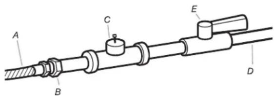
A. 3/8" flexible gas connector
B. 3/8" pipe to flare adapter fitting
C. 1/8" NPT minimum plugged tapping
D. 1/2" NPT gas supply line
E. Gas shut-off valve
GAS SUPPLY CONNECTION REQUIREMENTS
■se an elbow and a 3/8" flare x 3/8" NPT adapter fitting between the flexible gas connector and the dryer gas pipe, as needed to avoid kinking.
■se only pipe-joint compound. Do not use TEFLON® tape.
This dryer must be connected to the gas supply line with a listed flexible gas connector that complies with the standard for connectors for gas appliances, ANSI Z21.24 or CSA 6.10.
BURNER INPUT REQUIREMENTS
Elevations above 2,000 ft. (610 m):
■/hen installed above 2,000 ft. (610 m) a 4% reduction of the burner Btu rating shown on the model/serial number plate is required for each 1,000 ft. (305 m) increase in elevation.
Gas supply pressure testing
■he dryer must be disconnected from the gas supply piping system during pressure testing at pressures greater than 1/2 psi.
DRYER GAS PIPE
■he gas pipe that comes out through the rear of your dryer has a 3/8" male pipe thread.
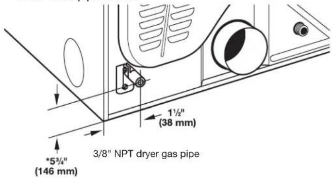
*NOTE: If the dryer is mounted on a pedestal, the gas pipe height must be an additional 10" (254 mm) or 15.5" (394 mm) from the floor, depending on the pedestal model. For a garage installation, the gas pipe height must be an additional 18" (460 mm) from the floor.
INSTALL LEVELING LEGS
WARNING
Excessive Weight Hazard
Use two or more people to move and install dryer.
Failure to do so can result in back or other injury.
1. Prepare dryer for leveling legs
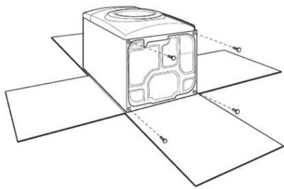
natural_image
Technical line drawing of a device casing with internal components and alignment lines (no text or symbols)To avoid damaging floor, use a large flat piece of cardboard from dryer carton; place under entire back edge of dryer. Firmly grasp dryer body (not console panel) and gently lay dryer down on cardboard.
2. Screw in leveling legs
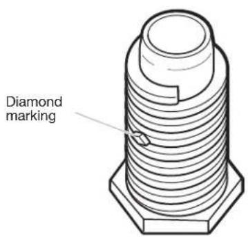
Examine leveling legs and locate the diamond marking. Screw legs into leg holes by hand – use a wrench to finish turning legs until diamond marking is no longer visible.
Place a carton corner post from dryer packaging under each of the two dryer back corners. Stand the dryer up. Slide the dryer on the corner posts until it is close to its final location. Leave enough room to connect the exhaust vent.
MAKE ELECTRICAL CONNECTION - U.S.A. ONLY
ELECTRICAL CONNECTION
Before you start: disconnect power.
1. Choose electrical connection type
Power supply cord 4-wire receptacle (NEMA Type 14-30R).
Go to "Power Supply Cord Connection."
Power supply cord 3-wire receptacle (NEMA Type 10-30R).
Go to "Power Supply Cord Connection."
4-wire direct connection:
Go to "Direct Wire Connection."
3-wire direct connection:
Go to "Direct Wire Connection."
NOTE: If local codes do not permit connection of a cabinet-ground conductor to neutral wire, go to "Optional External Ground for 3-Wire Connection." This connection may be used with either a power supply cord or a direct wire connection.
2. Remove terminal block cover
natural_image
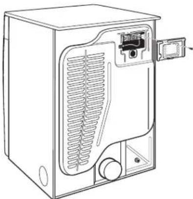
Line drawing of a refrigerator with ventilation slots and door handle (no text or symbols)Remove hold-down screw and terminal block cover.
Power Supply Cord Connection
Power Supply Cord:
WARNING

Fire Hazard
Use a new UL listed 30 amp power supply cord.
Use a UL listed strain relief.
Disconnect power before making electrical connections.
Connect neutral wire (white or center wire) to center terminal (silver).
Ground wire (green or bare wire) must be connected to green ground connector.
Connect remaining 2 supply wires to remaining 2 terminals (gold).
Securely tighten all electrical connections.
Failure to do so can result in death, fire, or electrical shock.
Power supply cord strain relief
1. Attach power supply cord strain relief

Remove the screws from a 3/4" (19 mm) UL Listed strain relief. Put the tabs of the two clamp sections (C) into the hole below the terminal block opening (B) so that one tab is pointing up (A) and the other is pointing down (D), and hold in place. Tighten strain relief screws just enough to hold the two clamp sections (C) together.
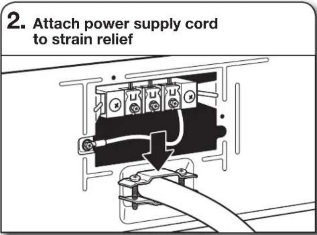
Put power supply cord through the strain relief. Be sure that the wire insulation on the power supply cord is inside the strain relief. The strain relief should have a tight fit with the dryer cabinet and be in a horizontal position. Do not further tighten strain relief screws at this point.
If your outlet looks like this:
Power supply cord 4-wire receptacle
(NEMA Type 14-30R):
Go to "4-Wire Power Supply Cord
Connection" on this page.
Power supply cord 3-wire receptacle
(NEMA Type 10-30R):
Go to "3-Wire Power Supply Cord
Connection" on page 13.
4-Wire Power Supply Cord Connection
IMPORTANT: A 4-wire connection is required for mobile homes and where local codes do not permit the use of 3-wire connections.
natural_image
Simple line drawing of a wall socket with three outlets (no text or symbols)4-wire receptacle (NEMA type 14-30R)
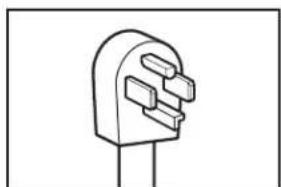
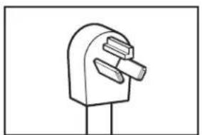
natural_image
Simple line drawing of a plug with three slots (no text or symbols)4 prong plug
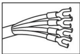
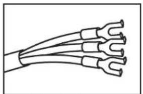
natural_image
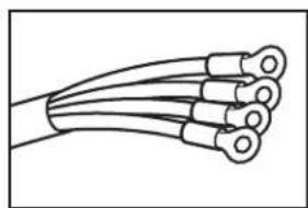
Diagram of a multi-woven electrical cable with multiple leads (no text or symbols)Spade terminals with upturned ends
natural_image
Line drawing of a multi-core cable with multiple leads (no text or symbols)Ring terminals
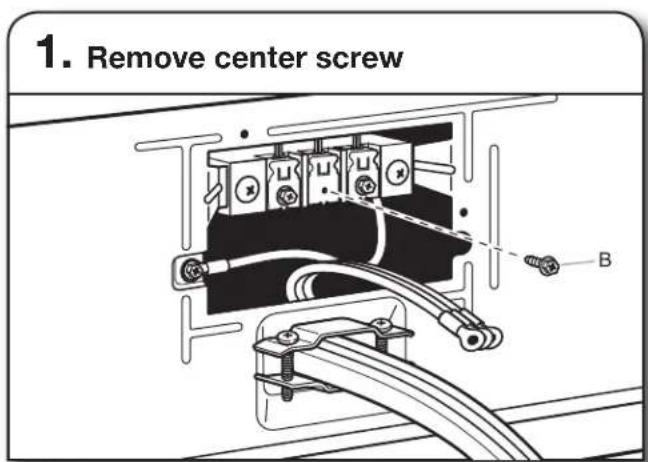
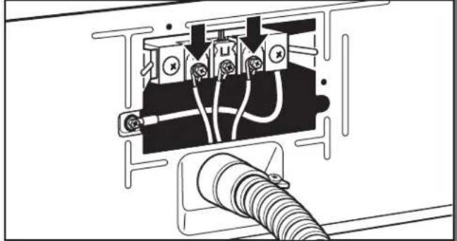
Remove center terminal block screw (B). Remove neutral ground wire (E) from green external ground conductor screw (A).
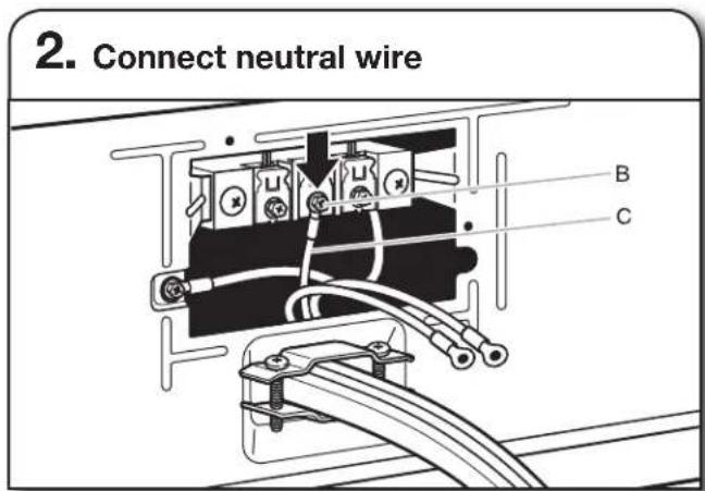
Connect neutral ground wire (E) and neutral wire (white or center) (C) of power supply cord under center terminal block screw (B). Tighten screw.
Connect ground wire (F) (green or bare) of power supply cord under green external ground conductor screw (A). Tighten screw.
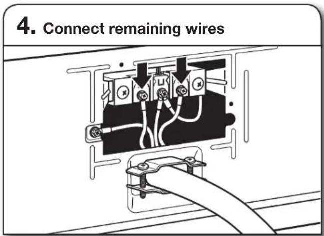
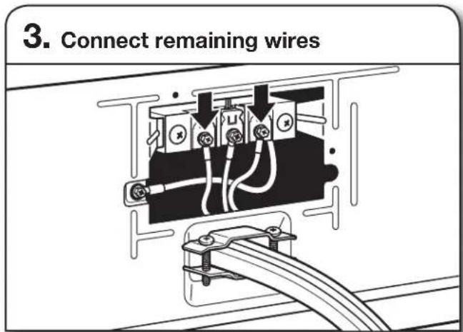
Connect remaining wires under outer terminal block screws. Tighten screws. Finally, reinsert tab of terminal block cover into slot of dryer rear panel. Secure cover with hold-down screw. Now go to "Venting Requirements."
3-Wire Power Supply Cord Connection
Use where local codes permit connecting cabinet-ground conductor to neutral wire.
natural_image
Simple line drawing of a wall socket with three circular indicators (no text or symbols)3-wire receptacle (NEMA type 10-30R)
natural_image
Simple line drawing of a mobile phone mount (no text or symbols)3 prong plug
natural_image
Line drawing of a multi-wire electrical cable with multiple leads (no text or symbols)Spade terminals with upturned ends

natural_image
Line drawing of three coaxial cables with circular end caps (no text or symbols)Ring terminals
Remove center terminal block screw (B).
Connect neutral wire (white or center) (C) of power supply cord under center terminal block screw (B). Tighten screw.
Connect remaining wires under outer terminal block screws. Tighten screws. Finally, reinsert tab of terminal block cover into slot of dryer rear panel. Secure cover with hold-down screw. Now go to "Venting Requirements."
Direct Wire Connection
For direct wire installations:
WARNING
Fire Hazard
Use 10 gauge copper wire.
Use a UL listed strain relief.
Disconnect power before making electrical connections.
Connect neutral wire (white or center wire) to center terminal (silver).
Ground wire (green or bare wire) must be connected to green ground connector.
Connect remaining 2 supply wires to remaining 2 terminals (gold).
Securely tighten all electrical connections.
Failure to do so can result in death, fire, or electrical shock.
Direct wire strain relief
- Attach direct wire strain relief
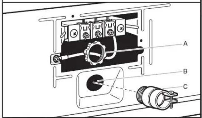
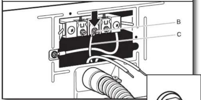
Unscrew the removable conduit connector (A) and any screws from a 3/4" (19 mm) UL Listed strain relief. Put the threaded section of the strain relief (C) through the hole below the terminal block opening (B). Reaching inside the terminal block opening, screw the removable conduit connector (A) onto the strain relief threads and tighten securely.
- Attach direct wire cable to strain relief
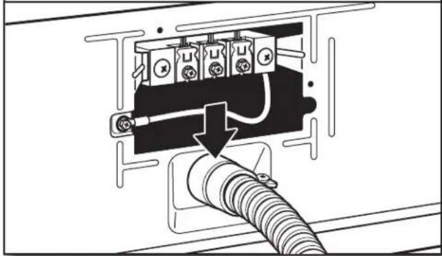
natural_image
Diagram of an electrical outlet with a coiled cable and a downward arrow indicating a component (no text or symbols present)Put direct wire cable through the strain relief. The strain relief should have a tight fit with the dryer cabinet and be in a horizontal position. Tighten strain relief screw against the direct wire cable.
If your wiring looks like this:
4-wire direct connection:
Go to "4-Wire Direct Wire Connection" on this page.
3-wire direct connection:
Go to "3-Wire Direct Wire Connection" on page 15.
4-Wire Direct Wire Connection
IMPORTANT: A 4-wire connection is required for mobile homes and where local codes do not permit 3-wire connections.
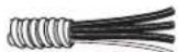
- Prepare your 4-wire cable for direct connection
Direct wire cable must have 5 ft. (1.52 m) of extra length so dryer may be moved if needed.
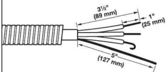
Strip 5" (127 mm) of outer covering from end of cable, leaving bare ground wire at 5" (127 mm). Cut 1½" (38 mm) from remaining three wires. Strip insulation back 1" (25 mm). Shape ends of wires into hooks.
Remove center terminal block screw (B). Remove neutral ground wire (E) from green external ground conductor screw (A).
Connect neutral ground wire (E) and place hooked end (hook facing right) of neutral wire (white or center wire) (C) of direct wire cable under center screw of terminal block (B). Squeeze hooked ends together and tighten screw.
Connect ground wire (green or bare) (F) of direct wire cable under green external ground conductor screw (A). Tighten screw.
Place hooked ends of remaining direct wire cable wires under outer terminal block screws (hooks facing right). Squeeze hooked ends together and tighten screws. Finally, reinsert tab of terminal block cover into slot of dryer rear panel. Secure cover with hold-down screw. Now go to "Venting Requirements."
3-Wire Direct Wire Connection
Use where local codes permit connecting cabinet-ground conductor to neutral wire.
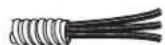
Direct wire cable must have 5 ft. (1.52 m) of extra length so dryer may be moved if needed.
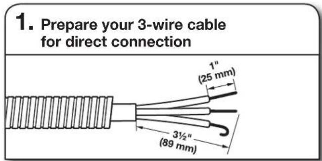
Strip 3 ^1/2 " (89 mm) of outer covering from end of cable. Strip insulation back 1" (25 mm). If using 3-wire cable with ground wire, cut bare wire even with outer covering. Shape wire ends into hooks.
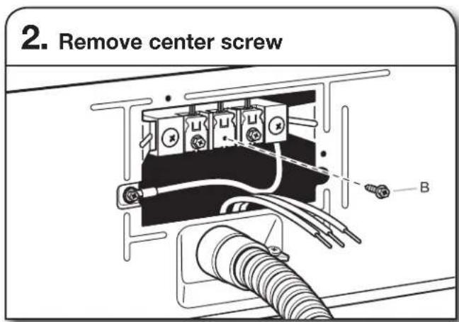
Remove center terminal block screw (B).
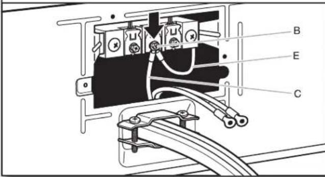
3. Connect neutral wire
Place hooked end of neutral wire (white or center) (C) of direct wire cable under center terminal block screw (B), hook facing right. Squeeze hooked end together. Tighten screw.

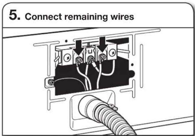
4. Connect remaining wires
natural_image
Pure electrical circuit lines without any symbolsPlace hooked ends of remaining direct wire cable wires under outer terminal block screws (hooks facing right). Squeeze hooked ends together and tighten screws. Finally, reinsert tab of terminal block cover into slot of dryer rear panel. Secure cover with hold-down screw. Now go to "Venting Requirements."
Optional External Ground for 3-Wire Connection (Power Supply Cord Shown)
IMPORTANT: You must verify with a qualified electrician that this grounding method is acceptable before connecting.
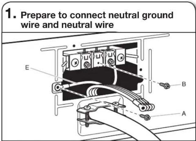
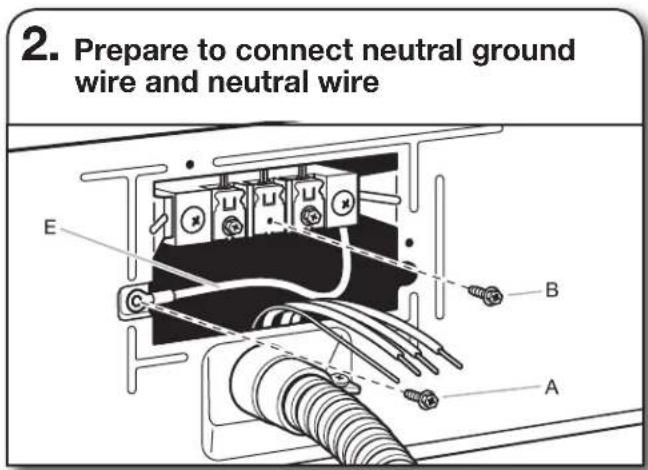
1. Prepare to connect neutral ground wire and neutral wire

Install the correct strain relief for your electrical connection method, as shown on page 12 or 14.
Remove center terminal block screw (B). Remove neutral ground wire (E) from green external ground conductor screw (A).
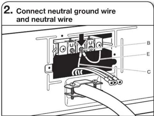
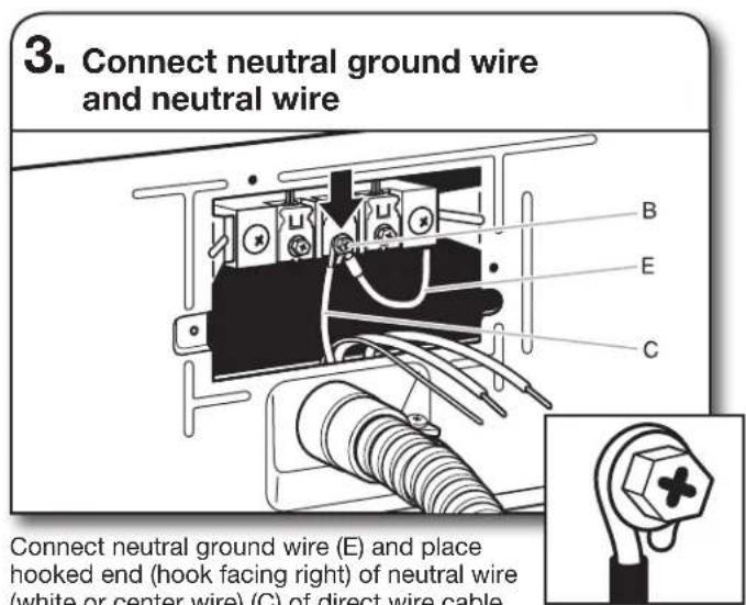
2. Connect neutral ground wire and neutral wire
Connect neutral ground wire (E) and neutral wire (white or center wire) (C) of power supply cord or cable under center terminal block screw (B). Tighten screw.
3. Connect remaining wires
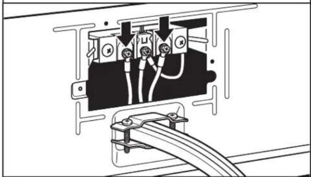
natural_image
Technical line drawing of an electrical outlet with wires and connectors (no text or symbols)Place ends of remaining wires under outer terminal block screws. Tighten screws.
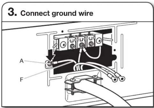
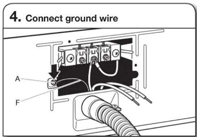
4. Connect external ground wire
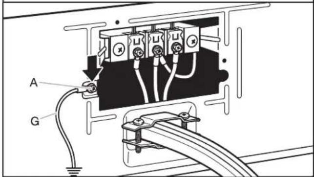
Connect a separate copper ground wire (G) under the green external ground conductor screw (A) to an adequate ground. Finally, reinsert tab of terminal block cover into slot of dryer rear panel. Secure cover with hold-down screw. Now go to "Venting Requirements."
MAKE GAS CONNECTION
(Gas models only)
WARNING
Explosion Hazard
Use a new CSA International approved gas supply line.
Install a shut-off valve.
Securely tighten all gas connections.
If connected to propane, have a qualified person make sure gas pressure does not exceed 13" (33 cm) water column.
Examples of a qualified person include:
licensed heating personnel,
authorized gas company personnel, and authorized service personnel.
Failure to do so can result in death, explosion, or fire.
2. Plan pipe fitting connection (Option 1)
A. 3/8" flexible gas connector
B. 3/8" dryer gas pipe
C. 3/8" to 3/8" pipe elbow
D. 3/8" pipe-to-flare adapter fitting
A combination of pipe fittings must be used to connect dryer to existing gas line. A recommended connection is shown. Your connection may be different, according to supply line type, size, and location.
1. Connect gas supply to dryer
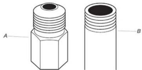
natural_image
Technical line drawing of two mechanical components labeled A and B, showing threaded ends (no text or symbols beyond labels)A. Flared male fitting
B. Non-flared male fitting
Remove red cap from gas pipe. Using a wrench to tighten, connect gas supply to dryer. Use pipe-joint compound on threads of all non-flared male fittings. If flexible metal tubing is used, be sure there are no kinks.
NOTE: For propane gas connections, you must use pipe-joint compound resistant to action of propane gas. Do not use TEFLON® tape.
3. Open shut-off valve
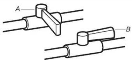
natural_image
Technical line drawing of two mechanical components labeled A and B, connected by rods (no text or symbols beyond labels)A. Closed valve
B. Open valve
Open shut-off valve in supply line; valve is open when handle is parallel to gas pipe. Then, test all connections by brushing on an approved noncorrosive leak-detection solution. Bubbles will show a leak. Correct any leak found.
VENTING
Venting Requirements
WARNING

Fire Hazard
Use a heavy metal vent.
Do not use a plastic vent.
Do not use a metal foil vent.
Failure to follow these instructions can result in death or fire.
WARNING: To reduce the risk of fire, this dryer MUST BE EXHAUSTED OUTDOORS.
IMPORTANT: Observe all governing codes and ordinances. Dryer exhaust must not be connected into any gas vent, chimney, wall, ceiling, attic, crawlspace, or a concealed space of a building. Only rigid or flexible metal vent shall be used for exhausting.
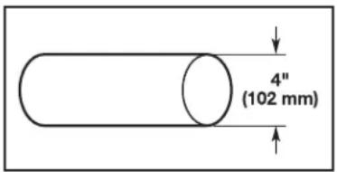
4" (102 mm) heavy metal exhaust vent
■only a 4" (102 mm) heavy metal exhaust vent and clamps may be used.
■o not use plastic or metal foil vent.
Rigid metal vent:
■recommended for best drying performance and to avoid crushing and kinking.
Flexible metal vent: (Acceptable only if accessible to clean)
■Must be fully extended and supported in final dryer location.
■ remove excess to avoid sagging and kinking that may result in reduced airflow and poor performance.
■o not install in enclosed walls, ceilings, or floors.
■he total length should not exceed 7 ^3/4 ft. (2.4 m).
The length of flexible metal vent used must be included in the overall vent system design as shown in the “Vent System Charts.”
NOTE: If using an existing vent system, clean lint from entire length of the system and make sure exhaust hood is not plugged with lint. Replace plastic or metal foil vents with rigid metal or flexible metal vents. Review “Vent System Charts” and, if necessary, modify existing vent system to achieve best drying performance.
Exhaust hoods:
In exhaust hood should cap the vent to keep rodents and insects from entering the home.
Must be at least 12" (305 mm) from ground or any object that may obstruct exhaust (such as flowers, rocks, bushes, or snow).
■o not use an exhaust hood with a magnetic latch.
Recommended Styles:
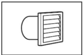
natural_image
Simple line drawing of a ventilation duct with a curved base and slatted top (no text or symbols)Louvered Hood
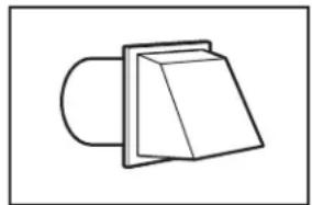
natural_image
Simple line drawing of a 3D object resembling a folded paper or bracket (no text or symbols)Box Hood
Acceptable Style:
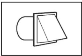
natural_image
Simple line drawing of a mechanical component or bracket (no text or symbols)Angled Hood
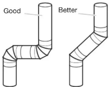
Elbows:
45° elbows provide better airflow than 90° elbows.
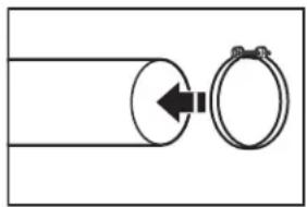
Clamps:
■se clamps to seal all joints.
■xhaust vent must not be connected or secured with screws or other fastening devices that extend into interior of duct and catch lint. Do not use duct tape.
natural_image
Simple line drawing of a pipe with a circular component and a ring, no text or symbols present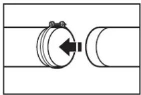
natural_image
Pure mechanical diagram showing a cylindrical component with an arrow indicating direction, no text or symbols presentPlan Vent System
Recommended exhaust installation:
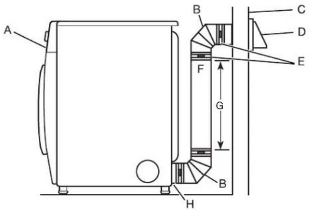
A. Dryer
B. Elbow
C. Wall
D. Exhaust hood
E. Clamps
F. Rigid metal or flexible metal vent
G. Vent length necessary to connect elbows
H. Exhaust outlet
WARNING

Fire Hazard
Cover unused exhaust holes with a manufacturer's exhaust cover kit.
Contact your local dealer.
Failure to follow these instructions can result in death, fire, electrical shock, or serious injury.
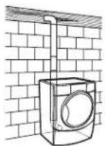
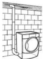
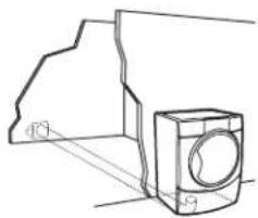
Optional exhaust installations:
This dryer can be converted to exhaust out the right side, left side (all models except long vent), or through the bottom. If you prefer, you may contact your local dealer to have the dryer converted.
A
B
natural_image
Technical line drawing of a mechanical component with no visible text or symbolsC
A. Standard rear offset exhaust installation
B. Left- or right-side exhaust installation
C. Bottom exhaust installation
Special provisions for mobile homes:
Exhaust vent must be securely fastened to a noncombustible portion of mobile home and must not terminate beneath the mobile home. Terminate exhaust vent outside.
natural_image
Technical line drawing of a mechanical assembly with no visible text or symbolsDetermine vent path:
■elect route that will provide straightest and most direct path outdoors.
■lan installation to use fewest number of elbows and turns.
■/hen using elbows or making turns, allow as much room as possible.
■end vent gradually to avoid kinking.
■se as few 90° turns as possible.
Determine vent length and elbows needed for best drying performance:
■se the following "Vent System Charts" to determine type of vent material and hood combinations acceptable to use.
NOTE: Do not use vent runs longer than those specified in "Vent System Charts."
Exhaust systems longer than those specified will:
■horten life of dryer.
■reduce performance, resulting in longer drying times and increased energy usage.
The "Vent System Charts" provide venting requirements that will help achieve best drying performance.
| Standard Vent System Chart | ||
| Number of 90°elbows | Type of vent Angled hoods | |
| 0 | Rigid metal 64 ft. (20 m) | |
| 1 | Rigid metal 54 ft. (16.5 m) | |
| 2 | Rigid metal 44 ft. (13.4 m) | |
| 3 | Rigid metal 35 ft. (10.7 m) | |
| 4 | Rigid metal 27 ft. (8.2 m) | |
| Long Vent System Chart | ||
| Number of 90° elbows | Type of vent Angled hoods | |
| 0 | Rigid metal 160 ft. (48.8 m) | |
| 1 | Rigid metal 150 ft. (45.7 m) | |
| 2 | Rigid metal 140 ft. (42.7 m) | |
| 3 | Rigid metal 130 ft. (39.6 m) | |
| 4 | Rigid metal 120 ft. (36.6 m) | |
To determine if your model has a long vent system, refer to the type code located on the serial number plate in the inner door well. Example: An electric model would be DJAV - ELE - XXXXXXX-XXX. A gas model would be DJAV - NAT - XXXXXXX-XXX.
NOTE: For long vent systems, use of box/louvered hoods will improve venting regardless of length.
Install Vent System
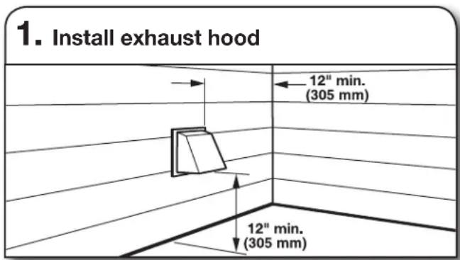
Install exhaust hood and use caulking compound to seal exterior wall opening around exhaust hood.
Vent must fit over the exhaust hood. Secure vent to exhaust hood with 4" (102 mm) clamp. Run vent to dryer location using straightest path possible. Avoid 90° turns. Use clamps to seal all joints. Do not use duct tape, screws, or other fastening devices that extend into interior of vent to secure vent, because they can catch lint.
CONNECT INLET HOSE (STEAM MODEL ONLY)
For non-steam models, skip to "Connect Vent."
The dryer must be connected to the cold water faucet using the new inlet hoses (not supplied). Do not use old hoses.
NOTE: Replace inlet hoses after 5 years of use to reduce the risk of hose failure. Record hose installation or replacement dates on the hoses for future reference.
Periodically inspect and replace hoses if bulges, kinks, cuts, wear, or leaks are found.
1. Turn cold water off, remove hose, and replace rubber washer

Turn cold water faucet off and remove washer inlet hose. Remove old rubber washer from inlet hose and replace with new rubber washer.
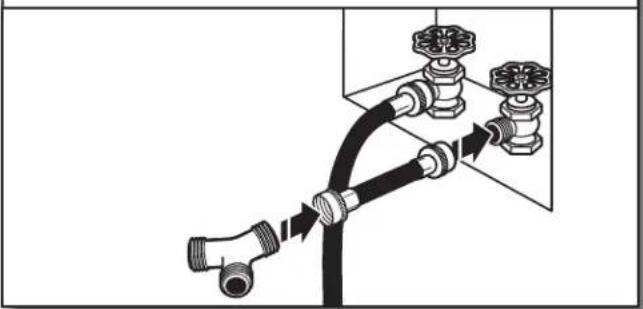
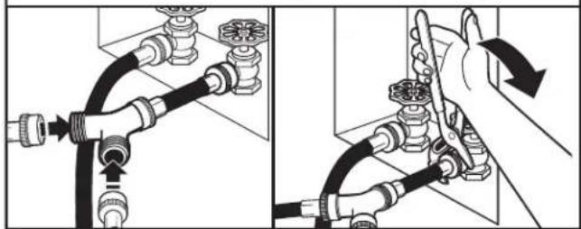
2. Attach short hose and "Y" connector
natural_image
Diagram of a pipe connection with valves and fittings, showing fluid flow direction (no text or labels)Attach 2 ft. (0.6 m) inlet hose to cold water faucet. Screw on coupling by hand until it is seated on faucet. Then attach "Y" connector to male end of the 2 ft. (0.6 m) inlet hose. Screw on coupling by hand until it is seated on connector.
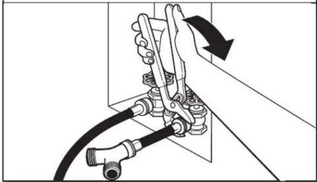
3. Tighten couplings
natural_image
Mechanical assembly diagram showing a hand operating a valve with hoses and a rotating arrow (no text or symbols)Using pliers, tighten the couplings with additional 2/3 turn. NOTE: Do not overtighten. Damage to the coupling can result.
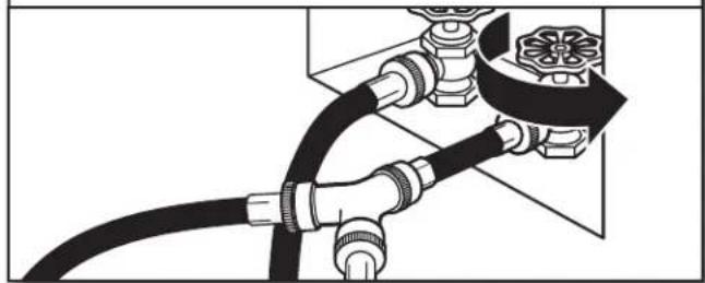
4. Attach long hose to "Y" connector and tighten couplings
natural_image
Two-step diagram showing pipe installation and valve assembly, with no visible text or symbolsAttach one of the 5 ft. (1.5 m) inlet hose ends to the "Y" connector. Attach washer cold inlet hose to other side of "Y" connector. Screw on coupling by hand until it is seated on connector. Using pliers, tighten the couplings an additional 2/3 turn.
NOTE: Do not overtighten. Damage to the coupling can result.
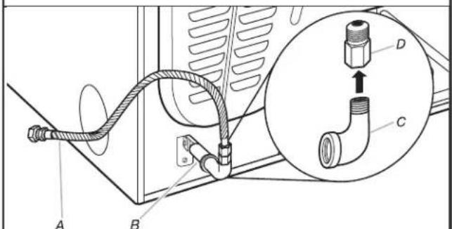
5. Attach long hose to dryer fill valve and tighten coupling
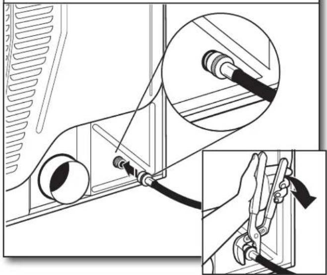
natural_image
Technical diagram showing cable installation with magnified detail of connector detail (no text or symbols)Remove protective cap from water inlet valve. Attach other end of long hose to fill valve at bottom of dryer back panel. Screw on coupling by hand until it is seated on fill valve connector. Using pliers, tighten the couplings an additional 2/3 turn.
NOTE: Do not overtighten. Damage to the coupling can result.
6. Turn on cold water faucet
natural_image
Pure electrical circuit lines without any symbolsCheck that the water faucets are turned on.
7. Check for leaks
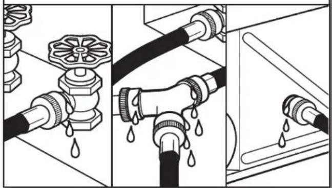
natural_image
Three-panel illustration showing pipe fittings and water droplets during installation (no text or symbols)Check for leaks around "Y" connector, faucet, and hoses.
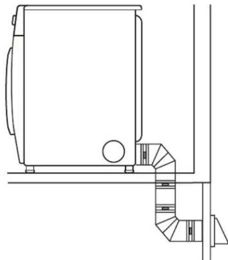
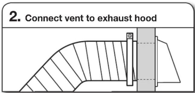
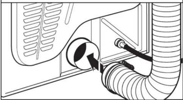
CONNECT VENT
1. Connect vent to exhaust outlet
natural_image
Diagram of a car air duct system with hoses and ventilation duct (no text or labels)Using a 4" (102 mm) clamp, connect vent to exhaust outlet in dryer. If connecting to existing vent, make sure vent is clean. Dryer vent must fit over dryer exhaust outlet and inside exhaust hood. Check that vent is secured to exhaust hood with a 4" (102 mm) clamp.
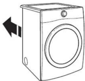
2. Move dryer to final location
natural_image
Line drawing of a washing machine with a circular vent and side door (no text or symbols)Move dryer to final location, taking care not to crush or kink vent or flexible gas line.
After dryer is in place, remove corner posts and cardboard from under dryer.
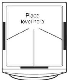
LEVEL DRYER
1. Level dryer
natural_image
Line drawing of a washing machine front panel with three circular buttons (no text or symbols)Check levelness of dryer from side to side. Repeat from front to back.
NOTE: The dryer must be level for the moisture sensing system to operate correctly.
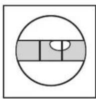
Not Level
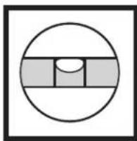
natural_image
Simple geometric diagram with a circle, horizontal bars, and a semicircle inside (no text or symbols)LEVEL
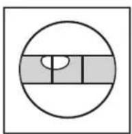
Not Level
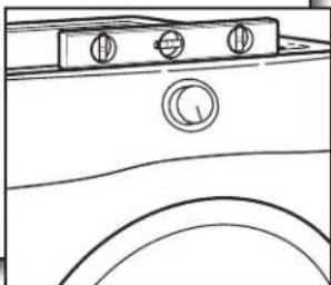
2. Adjust leveling legs
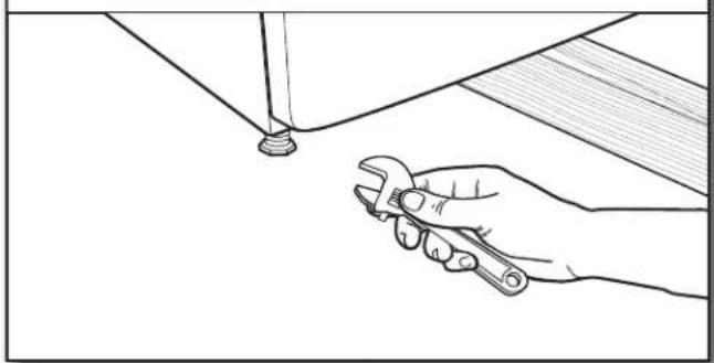
natural_image
Line drawing of a hand using a wrench to adjust or install a component (no text or symbols present)If dryer is not level, prop up using a wood block, use wrench to adjust legs up or down, and check again for levelness. Once dryer is level, make sure all four legs are snug against the floor and the dryer does not rock.
COMPLETE INSTALLATION CHECKLIST
☐ Check that all parts are now installed. If there is an extra part, go back through steps to see what was skipped.
☐ Check that you have all of your tools.
☐ Dispose of/recycle all packaging materials.
☐ Be sure the water faucets are on.
☐ Check for leaks around "Y" connector, faucet, and hoses.
☐ Check dryer's final location. Be sure vent is not crushed or kinked.
☐ Check that dryer is level. See "Level Dryer."
☐ Remove film on console and any tape remaining on dryer.
☐ Wipe dryer drum interior thoroughly with a damp cloth to remove any dust.
Read "Dryer Use" in your Use and Care Guide.
☐ If you live in a hard water area, use of a water softener is recommended to control the buildup of scale through the water system in the dryer. Over time, the buildup of lime scale may clog different parts of the water system, which will reduce product performance. Excessive scale buildup may lead to the need for certain part replacement or repair.
Electric Models:
☐ Plug into a grounded outlet.
Gas Models:
Plug into a grounded outlet.
☐ Check that gas supply is on.
□ Check for leaks.
☐ Check to be sure that the flexible gas line is not crushed or kinked.
All Models:
☐ Select a Timed Dry heated cycle and start dryer. Do not select Air Only Temperature setting.
If dryer will not start, check the following:
- Controls are set in a running or On position.
- Start button has been pressed firmly.
- Dryer is plugged into an outlet and/or electrical supply is connected.
- Household fuse is intact and tight, or circuit breaker has not tripped.
- Dryer door is closed.
This dryer automatically runs an installation diagnostic routine at the start of its first cycle.
NOTE: You may notice an odor when dryer is first heated. This odor is common when heating element is first used. The odor will go away.
DOOR REVERSAL (OPTIONAL)
The following instructions are for models with round and square-shaped doors.
Tools needed:
natural_image
Simple line drawing of a screwdriver (no text or symbols)Min. 8" (203 mm) long
TORX®, T20®, and
T25 ^® screwdrivers
natural_image
Line drawing of a screwdriver with a cylindrical head and threaded shaft (no text or symbols)2 Phillips screwdriver
REVERSE DOOR SWING: ROUND-SHAPED DOOR DOORS WITH ELECTRICAL WIRING:
WARNING
Electrical Shock Hazard
Disconnect power before servicing.
Replace all parts and panels before operating.
Failure to do so can result in death or electrical shock.
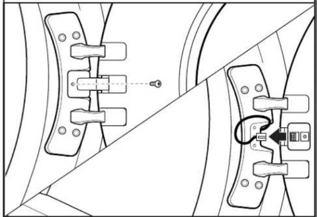
1. Disconnect wiring from door
natural_image
Technical line drawing of mechanical clamps and brackets (no text or symbols)Using a Phillips screwdriver, remove middle screw in hinge. Disconnect wiring. Tuck wiring into opening.
ALL DOORS:
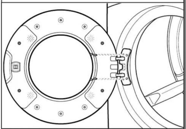
2. Remove door from dryer
natural_image
Technical line drawing of a mechanical component with circular flange and internal components (no text or symbols)IMPORTANT: If the protective film has not yet been removed from the dryer, peel the film from the dryer door before proceeding.
Using a T25 ^® screwdriver, remove the four screws securing the door hinge to the dryer and lift the door up and out to remove. Place the door on a soft towel or other non-scratch surface.
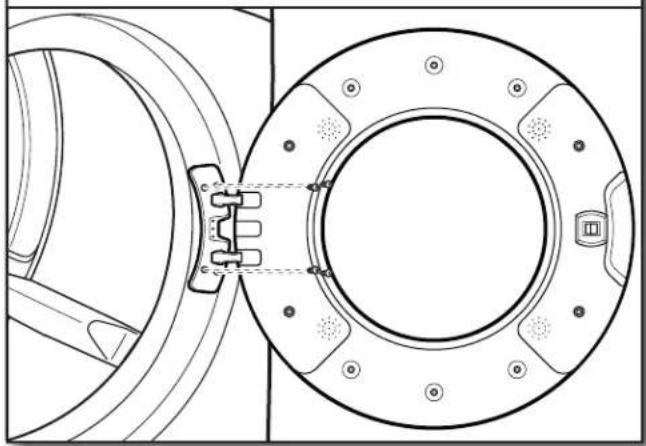
- Move the door strike
natural_image
Diagram showing two curved panels with circular elements and directional arrows, no text or symbols presentUsing a T25 ^® screwdriver, remove the two screws securing the door strike to the door frame of the dryer. Rotate the strike 180° and attach to the opposite side of dryer door frame with the two screws removed earlier, as shown.
- Remove inner door from outer door
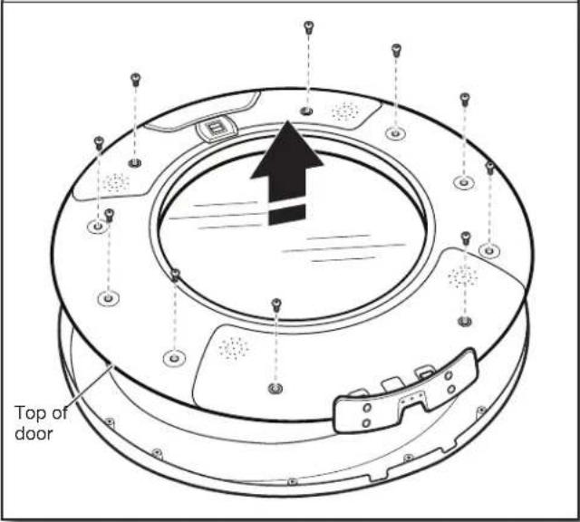
Position the door with the inside of the door facing up. Using a Phillips screwdriver, remove the 10 screws securing the inner door to the outer door.
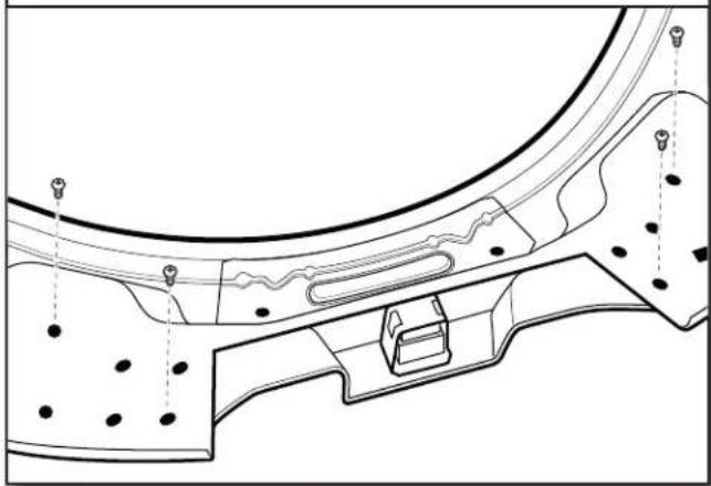
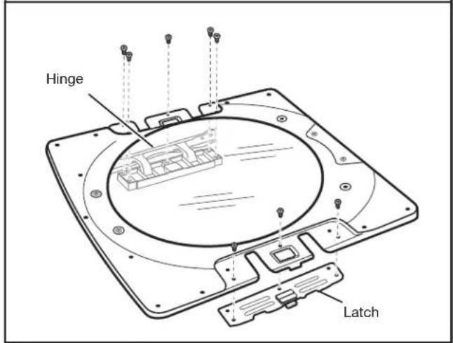
- Remove latch
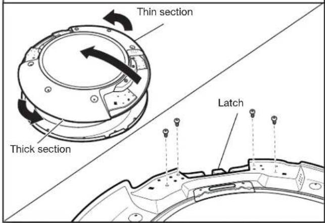
Flip and rotate the inner door 180° so that the thin section is at the top and the thick section is at the bottom. Using a T25® screwdriver, remove the four screws securing the latch plate in place.
- Remove hinge
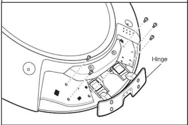
Using a T20 ^® screwdriver, remove the six screws holding the hinge assembly in place.
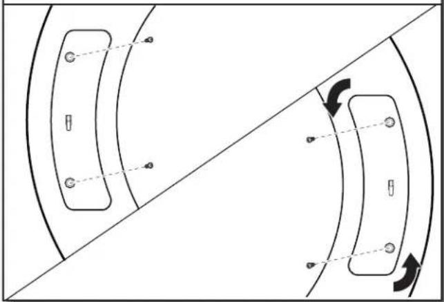
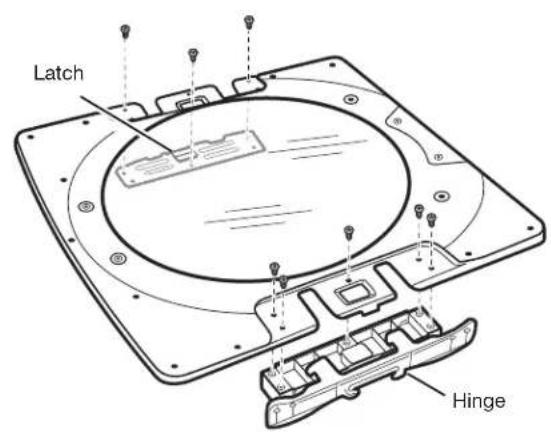
- Reinstall latch on opposite side
natural_image
Technical line drawing of a mechanical component with mounting holes and internal channels (no text or symbols)Using a T25 ^® screwdriver, reinstall the latch plate on the opposite side from which it was removed with the four screws removed earlier.
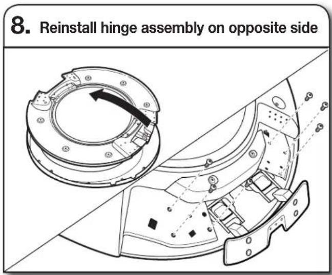
Flip over the inner door to the left. Using a T20 ^® screwdriver, reinstall the hinge assembly on the opposite side from which it was removed.
DOORS WITH ELECTRICAL WIRING:
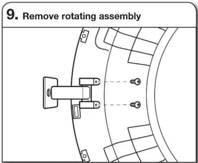
Lift off inner door assembly. Using a Phillips screwdriver, remove the two screws securing the rotating assembly to the door.
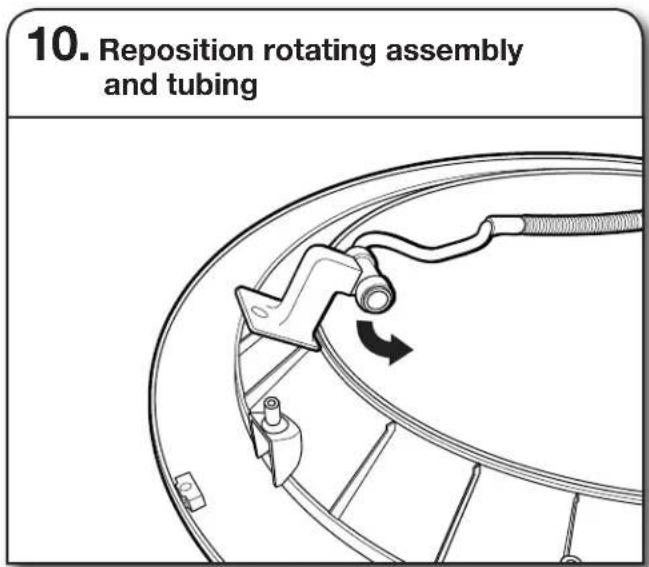
Reposition rotating assembly and tubing 180° to opposite side of the door.
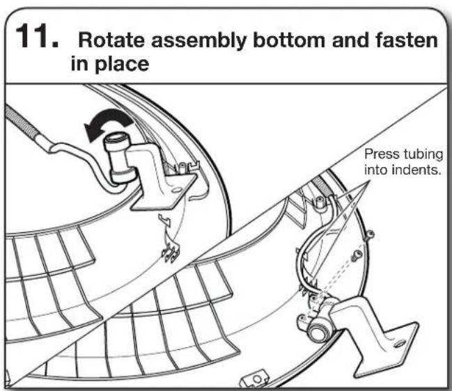
Rotate bottom of assembly 180° towards you and secure assembly with the two screws removed earlier, using a Phillips screwdriver. Press tubing into indents.
IMPORTANT: Make sure to swing hinge down in front of rotating assembly (see Step 12).
ALL DOORS: DOORS WITH ELECTRICAL WIRING:
- Reinstall inner door assembly
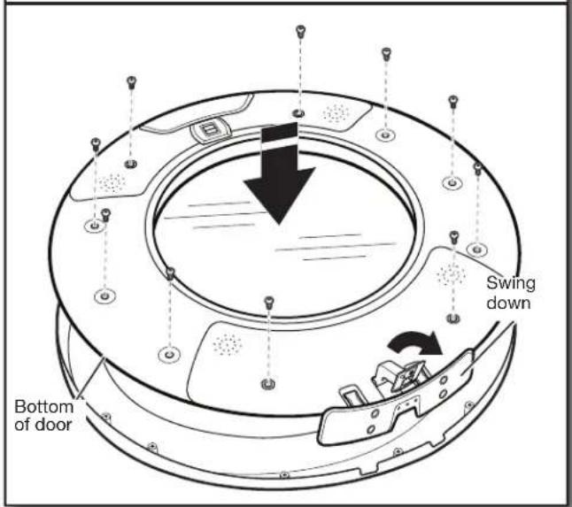
Position the door with the inside of the door facing up. Using a Phillips screwdriver, reinstall the 10 screws removed earlier, securing the inner door to the outer door.
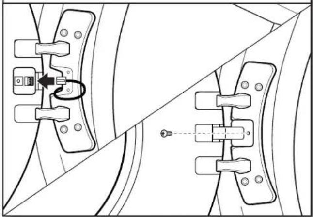
- Reconnect wiring
natural_image
Technical line drawing of mechanical clamps and brackets (no text or symbols)Plug in wire. Using a Phillips screwdriver, secure the rotating assembly to the hinge with the screw removed earlier.
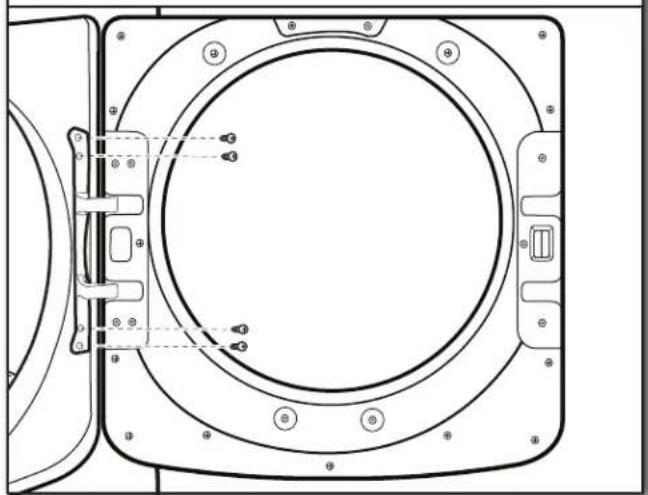
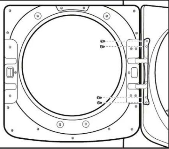
- Reinstall door on dryer
natural_image
Technical line drawing of a mechanical component with mounting holes and internal brackets (no text or symbols)Doors with electrical wiring: Pull the wire through the front panel opening before reinstalling the door.
Insert the tabs on the hinge into the mounting slot and slide down to engage the top tab. Secure in place with the four T25 ^® screws removed earlier.
REVERSE DOOR SWING: SQUARE-SHAPED DOOR
- Remove door from dryer
Using a T25 ^® screwdriver, remove the four screws securing the door hinge to the dryer and lift up and out to remove the door. Place the door on a soft towel or other non-scratch surface. Retain or set aside the four screws.
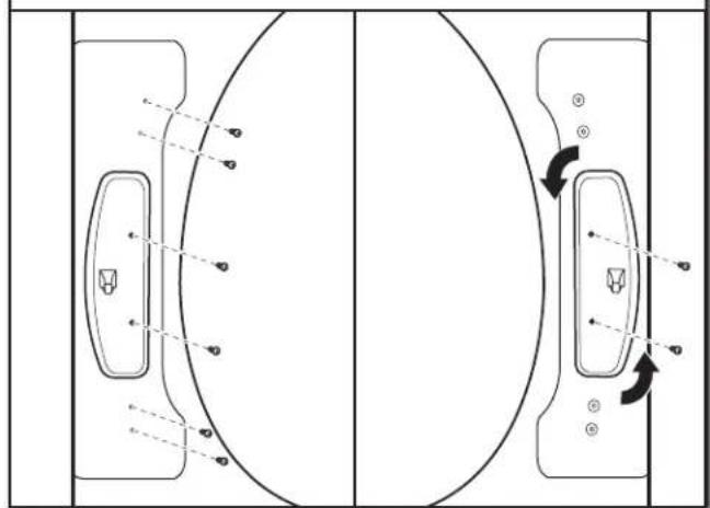
- Move the door strike
natural_image
Technical diagram of a door handle mechanism with arrows indicating rotation and adjustment points (no text or labels)Using a T25 ^® screwdriver, remove the two screws securing the door strike to the door frame of the dryer. Remove the four screws above and below the door strike and set aside for later use. Rotate the strike 180° and attach to the opposite side of dryer door frame, as shown.
- Remove inner door from outer door
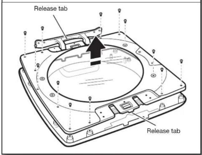
Position the door with the inside of the door facing up. Using a Phillips screwdriver, remove the 13 screws securing the inner door to the outer door. Lift off the inner door and set aside.
NOTE: There is a small release tab on each side of the door. If the inner and outer door do not separate easily, slide a credit card, putty knife, or similar flat object between the inner and outer doors at the locations shown to release the tab.
- Remove hinge and latch from inner door
Using a T25 ^® screwdriver, remove the three screws securing the latch plate and the five screws holding the hinge assembly in place.
- Reinstall hinge and latch on opposite sides
Using a T25 ^® screwdriver, reinstall the latch plate and hinge assembly on the opposite sides from which they were removed.
- Reattach door to dryer
natural_image
Technical line drawing of a circular mechanical component with mounting holes and internal features (no text or symbols)Using a T25 ^® screwdriver, reinstall the four screws securing the door hinge to the dryer.
- Reattach inner door to outer door

natural_image
Technical line drawing of a device casing with internal components and a downward arrow indicating a component (no text or symbols present)Position the inner door on the outer door assembly. Using a Phillips screwdriver, secure with the 13 screws removed earlier.
SÉCURITÉ DE LA SÉCHEUSE
natural_image
Line drawing of a screwdriver with a cylindrical head and threaded shaft (no text or symbols)natural_image
Simple line drawing of a screwdriver (no text or symbols)natural_image
Simple line drawing of a screwdriver with a handle and screw head (no text or symbols)natural_image
Simple diagram with three circular symbols inside a rectangular box (no text or labels)Niveau
natural_image
Simple line drawing of a tape measure (no text or symbols)Mètre-ruban

natural_image
Line drawing of a pair of pliers (no text or symbols)Pince

natural_image
Simple line drawing of a flat tool with a handle and central slot (no text or symbols)Couteau
natural_image
Line drawing of a pair of pliers (no text or symbols)natural_image
Two simple line drawings of laboratory pipettes: a cylindrical and a tool with a pointed tip, both without any text or symbols.natural_image
Line drawing of an adjustable wrench with a handle and screw spout (no text or symbols)natural_image
Line drawing of a pair of pliers with no text or symbolsnatural_image
Line drawing of an adjustable wrench (no text or symbols)natural_image
Line drawing of an adjustable wrench (no text or symbols)natural_image
Simple line drawing of a jar with a lid and handle (no text or symbols)natural_image
Illustration of three different types of threaded fasteners or bolts (no text or symbols present)natural_image
Simple line drawing of a T-shaped pipe fitting with two side flanges (no text or symbols)Connecteur en "Y"
natural_image
Pure electrical circuit lines without any symbolsnatural_image
Simple line drawing of a ring-shaped object (no text or symbols)natural_image
Coiled black cable or hose with two connectors, no text or symbols visiblenatural_image
Technical line drawing of a device casing with internal compartments and mounting points (no text or symbols)natural_image
Technical line drawing of two mechanical components labeled A and B, showing threaded ends (no text or symbols beyond labels)natural_image
Technical line drawing of two mechanical components labeled A and B, connected by rods (no text or symbols beyond labels)natural_image
Simple line drawing of a ventilation duct with a curved base and slatted top (no text or symbols)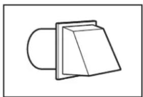
natural_image
Simple line drawing of a 3D object resembling a folded paper or block (no text or symbols)natural_image
Simple line drawing of a folded paper or plastic sheet with a curved handle (no text or symbols)Clapet incliné
Coudes :
natural_image
Simple line drawing of a pipe with a circular component and a ring, no text or symbols present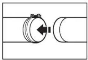
natural_image
Pure mechanical diagram showing a cylindrical component connected to a curved pipe (no text or symbols)natural_image
Technical line drawing of a mechanical component with no visible text or symbolsC
natural_image
Technical line drawing of a mechanical or architectural component with no visible text or symbolsnatural_image
Technical line drawing of a mechanical component with hatched fill and alignment markers (no text or symbols)natural_image
Mechanical assembly diagram showing a hand connecting a valve to a hose with directional arrow (no text or symbols)natural_image
Diagram showing two hands operating a pipe fitting with a valve, no text or symbols presentnatural_image
Technical diagram showing cable installation with magnified detail (no text or symbols)natural_image
Pure electrical circuit lines without any symbolsnatural_image
Three-panel illustration showing pipe fittings and water droplets during cleaning or repair (no text or symbols)RACCORDEMENT DU CONDUIT D'ÉVACUATION
natural_image
Diagram of a car air duct system with hoses and a valve, showing airflow direction (no text or labels)natural_image
Line drawing of a washing machine with a black arrow indicating leftward motion (no text or symbols)natural_image
Line drawing of a washing machine front panel with circular buttons (no text or symbols)natural_image
Line drawing of a hand holding a wrench, with a tool above a surface (no text or symbols)natural_image
Line drawing of a screwdriver with a flat head and threaded shaft (no text or symbols)Tournevis TORX®, T20® et T25®† de 8" (203 mm) min. de long
natural_image
Simple line drawing of a screwdriver (no text or symbols)natural_image
Technical line drawing of mechanical components with no visible text or symbolsnatural_image
Technical line drawing of a mechanical component with circular flange and mounting holes (no text or symbols)natural_image
Diagram showing two curved panels with circular elements and directional arrows, no text or symbols presentnatural_image
Technical line drawing of a mechanical component with mounting holes and internal features (no text or symbols)natural_image
Technical line drawing of a mechanical assembly with cross-sectional views and component annotations (no text or symbols)natural_image
Mechanical diagram showing a wheel assembly with a lever and rotating component (no text or symbols)natural_image
Technical line drawing of a mechanical assembly with no visible text or symbolsnatural_image
Technical line drawing of mechanical components with no visible text or symbolsnatural_image
Technical line drawing of a mechanical component with mounting holes and internal fasteners (no text or symbols)natural_image
Technical line drawing of a circular mechanical component with mounting holes and internal features (no text or symbols)natural_image
Diagram of a door panel with directional arrows indicating movement or force (no text or symbols)natural_image
Technical line drawing of a circular mechanical component with mounting holes and internal features (no text or symbols)natural_image
Technical line drawing of a device casing with internal components and a downward arrow indicating a component (no text or symbols present)
- DRYER INSTALLATION INSTRUCTIONS
- INSTRUCTIONS POUR L'INSTALLATION
- DE LA SÉCHEUSE
- Table of Contents Table des matières
- NOTES CONCERNANT L'INSTALLATION
- Your safety and the safety of others are very important.
- ! DANGER
- WARNING
- WARNING - "Risk of Fire"
- Fire Hazard
- ARNING:
- FIRE OR EXPLOSION HAZARD
- IMPORTANT SAFETY INSTRUCTIONS
- SAVE THESE INSTRUCTIONS
- INSTALLATION REQUIREMENTS Tools and Parts
- Phillips screwdriver
- Tools needed for gas installations:
- Parts supplied (all models):
- Parts needed (steam models):
- Parts needed (not supplied with dryer):
- If using a power supply cord:
- Optional Equipment (not supplied with dryer):
- LOCATION REQUIREMENTS
- Explosion Hazard
- You will need:
- DRYER DIMENSIONS
- Installation Clearances
- Installation spacing for recessed area or closet installation
- Mobile home – Additional installation requirements:
- Mobile home installations require:
- For mobile home installation of gas dryers:
- ELECTRICAL REQUIREMENTS - U.S.A. ONLY
- It is your responsibility:
- Electrical Connection
- If your outlet looks like this:
- If connecting by direct wire:
- GROUNDING INSTRUCTIONS
- ELECTRIC DRYER POWER HOOKUP - CANADA ONLY
- GAS SUPPLY REQUIREMENTS
- GAS TYPE
- Natural Gas:
- Propane Gas Conversion:
- GAS SUPPLY LINE
- Option 1 (Recommended Method)
- Option 2 (Alternate Method)
- In the U.S.A.:
- In Canada:
- GAS SUPPLY CONNECTION REQUIREMENTS
- BURNER INPUT REQUIREMENTS
- Gas supply pressure testing
- DRYER GAS PIPE
- INSTALL LEVELING LEGS
- Prepare dryer for leveling legs
- Screw in leveling legs
- MAKE ELECTRICAL CONNECTION - U.S.A. ONLY
- Choose electrical connection type
- Remove terminal block cover
- Power Supply Cord Connection
- Power supply cord strain relief
- Attach power supply cord strain relief
- 4-Wire Power Supply Cord Connection
- 3-Wire Power Supply Cord Connection
- Direct Wire Connection
- Direct wire strain relief
- If your wiring looks like this:
- 4-Wire Direct Wire Connection
- 3-Wire Direct Wire Connection
- Connect neutral wire
- Connect remaining wires
- Optional External Ground for 3-Wire Connection (Power Supply Cord Shown)
- Prepare to connect neutral ground wire and neutral wire
- Connect neutral ground wire and neutral wire
- Connect remaining wires
- Connect external ground wire
- MAKE GAS CONNECTION
- (Gas models only)
- Plan pipe fitting connection (Option 1)
- Connect gas supply to dryer
- Open shut-off valve
- VENTING
- Venting Requirements
- Rigid metal vent:
- Exhaust hoods:
- Elbows:
- Clamps:
- Plan Vent System
- Recommended exhaust installation:
- Optional exhaust installations:
- Special provisions for mobile homes:
- Determine vent path:
- Determine vent length and elbows needed for best drying performance:
- Install Vent System
- CONNECT INLET HOSE (STEAM MODEL ONLY)
- Turn cold water off, remove hose, and replace rubber washer
- Attach short hose and "Y" connector
- Tighten couplings
- Attach long hose to "Y" connector and tighten couplings
- Attach long hose to dryer fill valve and tighten coupling
- Turn on cold water faucet
- Check for leaks
- CONNECT VENT
- Connect vent to exhaust outlet
- Move dryer to final location
- LEVEL DRYER
- Level dryer
- Adjust leveling legs
- COMPLETE INSTALLATION CHECKLIST
- Electric Models:
- Gas Models:
- All Models:
- DOOR REVERSAL (OPTIONAL)
- REVERSE DOOR SWING: ROUND-SHAPED DOOR DOORS WITH ELECTRICAL WIRING:
- Disconnect wiring from door
- DOORS WITH ELECTRICAL WIRING:
- REVERSE DOOR SWING: SQUARE-SHAPED DOOR
- SÉCURITÉ DE LA SÉCHEUSE
- Coudes :
- RACCORDEMENT DU CONDUIT D'ÉVACUATION
Brand : MAYTAG
Model : MGD6630MBK
Category : Tumble dryer