
SmartRack SR42UWSP1 - Server rack Tripp Lite - Free user manual and instructions
Find the device manual for free SmartRack SR42UWSP1 Tripp Lite in PDF.

| Product Type | IT rack (storage cabinet) for 19-inch rack mounting |
| Brand | Tripp Lite |
| Model | SmartRack SR42UWSP1 |
| Rack Height | 42U (78.5 in / 1994 mm) |
| Width | 23.63 in (600 mm) |
| Depth | 43 in (1092 mm) |
| Cabinet Weight | 286 lb (130 kg) |
| Static Load Capacity | 3000 lb (1363 kg) |
| Rolling Load Capacity | 2250 lb (1022 kg) |
| Doors | Front reversible and lockable door, two lockable rear doors |
| Side Panels | 4 lockable side panels (removable) |
| Top Panel | Removable with pins |
| Material | Steel |
| Casters | 4 casters (minor adjustment), leveling feet for permanent support |
| Mounting Rails | 4 front/rear rails adjustable in 6 mm increments (depth from 101.6 mm to 1066.8 mm) |
| Grounding | Front and rear grounding point (M6 screw included, 8 AWG wire not supplied) |
| Included Accessories | 60 M6 screws, 60 cage nuts, 60 collar washers, 2 keys, mounting brackets, mounting hardware |
| Shock Pallet | Yes (SP1 model), allows reshipment with pre-installed equipment (max capacity 1250 lb) |
| Shipping Dimensions | 84 x 28 x 47 in (2146 x 705 x 1194 mm), weight 336 lb (152 kg) |
| Operating Conditions | Indoor, controlled environment, protected from moisture, dust and extreme temperatures |
| Warranty | 5-year limited |
| Safety Instructions | Do not move without assistance, install on level floor, secure to structure, do not pull by panels |
Frequently Asked Questions - SmartRack SR42UWSP1 Tripp Lite
User questions about SmartRack SR42UWSP1 Tripp Lite
0 question about this device. Answer the ones you know or ask your own.
Ask a new question about this device
Download the instructions for your Server rack in PDF format for free! Find your manual SmartRack SR42UWSP1 - Tripp Lite and take your electronic device back in hand. On this page are published all the documents necessary for the use of your device. SmartRack SR42UWSP1 by Tripp Lite.
USER MANUAL SmartRack SR42UWSP1 Tripp Lite
SmartRack® Enclosures
(Series Numbers: AG-039A, AGAC7006, AGAC7761, AG-0324, AG-00BE, AG-0325, AGAC7454, AG-0534, AG-0535, AG-0536)
Important Safety Instructions 2
Overview 2
Feature Identification 3
Enclosure Installation 4
Preparation 4
Unpacking 4
Placement 5
Leveling 6
Ground Connection 6
Enclosure Configuration 7
Adding or Removing Front and Rear Doors 7
Reversing Front Door 7
Adding or Removing Roof Panel 9
Adding or Removing Side Panels 9
Adjusting Mounting Rails and Cable Management Rails 10
Combining (Baying) Enclosures 11
Equipment Installation 11
Installing or Removing Cage Nuts 12
Specifications 12
Storage and Service 14
Warranty and Product Registration 14
Español 15
Français 29
Русский 43
WARRANTY REGISTRATION
Register your product today and be automatically entered to win an ISOBAR® surge protector in our monthly drawing!
tripplite.com/warranty


1111 W. 35th Street, Chicago, IL 60609 USA • tripplite.com/support
Copyright © 2022 Tripp Lite. All rights reserved.
Important Safety Instructions

SAVE THESE INSTRUCTIONS
All sections of this manual contain instructions and warnings that should be followed during the installation and use of the SmartRack Enclosures described in this manual. Read all instructions and warnings thoroughly before attempting to move, install or use the SmartRack Enclosures described in this manual. Failure to comply will create a risk of personal injury and property damage and may invalidate the warranty.
- Keep the enclosure in a controlled indoor environment, away from moisture, temperature extremes, flammable liquids and gasses, conductive contaminants, dust and direct sunlight.
- Leave adequate space at the front and rear of the enclosure for proper ventilation. Do not block, cover or insert objects into the external ventilation openings of the enclosure.
- The enclosure is extremely heavy. Use caution when handling the enclosure. Do not attempt to unpack, move or install it unassisted. Use a mechanical device such as a forklift or pallet jack to move the enclosure in the shipping container.
- Do not place any object on the enclosure, especially containers of liquid, and do not attempt to stack the enclosures.
- Inspect the shipping container and the enclosure for shipping damage. Do not use the enclosure if it is damaged.
- Leave the enclosure in the shipping container until it has been moved as close to the final installation location as possible. The casters are designed for minor position adjustments within the final installation area only. The casters are not designed for moving the enclosure over longer distances.
- The casters are not designed to provide long-term support for the enclosure after final installation. Use the levelers to provide long-term support.
- Install the enclosure in a structurally sound area with a level floor that is able to bear the weight of the enclosure, all equipment that will be installed in the enclosure and any other enclosures and/or equipment that will be installed nearby.
• Install the cabinet securely to the building structure, using the shipping brackets as illustrated in the Enclosure Installation section of this manual. - Do not push the enclosure from the side panels to move it. Pushing from the side panels will cause a tipping hazard.
- When rolling the enclosure on its casters, always push it from behind, never pull it toward you.
- A rolling enclosure can cause personal injury and property damage if not properly supervised. If rolling the enclosure down a ramp is required, use extreme caution. Do not attempt to use ramps that have a slope steeper than 1:12.
- Use caution when cutting packing materials. The enclosure could be scratched, causing damage not covered by the warranty.
- Save all packing materials for later use. Repacking and shipping the enclosure without the original packing materials may cause product damage that will void the warranty.
- Do not re-ship the enclosure with additional equipment unless the enclosure was shipped with a special shock pallet ("SP1" models only). The combined weight of the enclosure and installed equipment must not exceed the load capacity of the pallet. Tripp Lite is not responsible for any damage that occurs during re-shipment.
• DANGER: STABILITY HAZARD, RACKS ARE TO BE INSTALLED BY QUALIFIED SERVICE PERSONNEL ONLY. - Use of this equipment in life support applications where failure of this equipment can reasonably be expected to cause the failure of the life support equipment or to significantly affect its safety or effectiveness is not recommended.
Overview
SmartRack Enclosures accommodate all standard 19-inch rackmount equipment, regardless of vendor, and ship fully assembled for quick and easy deployment. They feature adaptable, heavy-duty cabinets in 24U, 42U, 45U, 47U and 48U heights, with or without side panels. Several models are available with an integrated shock pallet that allows resellers, integrators and enterprise customers to pre-configure equipment and re-ship the enclosures to the final installation site.
SmartRack Enclosures have variable mounting depths, ideal for servers. Integrated baying hardware enables cost-effective, orderly and efficient expansion. The cabinets include quick-release doors and side panels for convenient maintenance and split rear doors for improved access and reduced clearance requirements. Front access doors are reversible for installation flexibility. Front and rear doors and side panels are lockable.
Available SmartRack Enclosures
| Model # Rack Height Side Panels Shock Pallet | |||
| SR24UB 24U Yes No | |||
| SR24UBEXP 24U No No | |||
| SR24UBEXPSP1 24U No Yes | |||
| SR24UBSP1 24U Yes Yes | |||
| SR25UB 25U Yes Yes | |||
| SR42UB 42U Yes No | |||
| SRX42UB* | 42U Yes No | ||
| SR42UBCL | 42U Yes No | ||
| SR42UBDP | 42U Yes No | ||
| SRX42UBDP* | 42U Yes No | ||
| SRX42UBDPEXP* | 42U No No | ||
| SR42UBDPWD | 42U Yes No | ||
| SRX42UBDPWD* | 42U Yes No | ||
| SRX42UBDPWDEXP* | 42U No | No | |
| SR42UBEXP 42U No | No | ||
| SRX42UBEXP* | 42U No | No | |
| SR42UBEXPND | 42U No | No | |
| SR42UBEXPSP1 42U No Yes | |||
| SR42UBSP1 42U Yes Yes | |||
| SR42UBWD | 42U Yes No | ||
| Model # Rack Height Side Panels Shock Pallet | |||
| SRX42UBWD* | 42U Yes No | ||
| SRX42UBWDEXP* | 42U No | No | |
| SR42UBWDCL | 42U Yes No | ||
| SR45UB 45U Yes No | |||
| SRX47UB* | 47U Yes No | ||
| SRX47UBEXP* | 47U No | No | |
| SRX47UBDP* | 47U Yes No | ||
| SRX47UBDPEXP* | 47U No | No | |
| SRX47UBWD* | 47U Yes No | ||
| SRX47UBWDEXP* | 47U No | No | |
| SRX47UBDPWD* | 47U Yes No | ||
| SRX47UBDPWDEXP* | 47U No | No | |
| SR48UB 48U Yes No | |||
| SR48UBCL | 48U Yes No | ||
| SR48UBDP | 48U Yes No | ||
| SR48UBDPWD | 48U Yes No | ||
| SR48UBEXP 48U No | No | ||
| SR48UBEXPSP1 48U No Yes | |||
| SR48UBSP1 48U Yes Yes | |||
| SR50UB 50U Yes No | |||
| SR52UB 52U Yes No | |||
| SR52UBDP | 52U Yes No | ||
| SR55UB 55U Yes No | |||
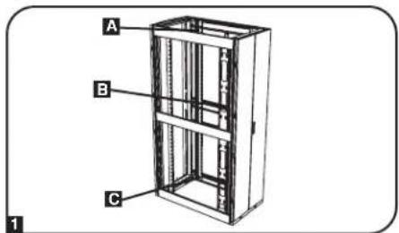
Feature Identification
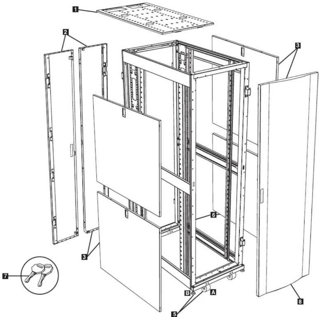
Model SR42UB is shown. The other models have similar features, with the differences noted.
1 Roof Panel
2 Locking Split Rear Doors
3 Locking Side Panels (24U enclosures use 2 side panels instead of 4. Side panels are not included with "EXP" models.)
4 Cable Management Rails
5 Casters A and Levelers B
6 Mounting Rails (Provide horizontal and vertical mounting points for equipment.)
7 Keys (One for the doors and one for the side panels.)
8 Locking Reversible Front Door
Not Shown: Mounting hardware, documentation, shipping brackets and other shipping materials.
Enclosure Installation

Caution! Read All Instructions and Warnings Before Installation!

WARNING: The rack enclosure is extremely heavy. Do not attempt to unpack, move or install the enclosure without assistance. Until it has been properly installed and stabilized, the enclosure is prone to tipping and could cause property damage and/or personal injury. Use extreme caution when handling the enclosure and be sure to follow all handling and installation instructions. Do not attempt to install equipment without first stabilizing the enclosure.
Preparation
The enclosure must be installed in a structurally sound area with a level floor that is able to bear the weight of the enclosure, all the equipment that will be installed in the enclosure and any other enclosures and/or equipment that will be installed nearby. Before unpacking the enclosure, you should transport the shipping container closer to the final installation location to minimize the distance you will need to move the unit after the protective packaging has been removed. If you plan to store the enclosure for an extended period before installation, follow the instructions in the Storage and Service section.
You need several tools (user-supplied):
• 13 mm Open-end Wrench
• 18 mm Open-end Wrench
- Utility Blade
- Carpenter's Level
• Phillips-head Screwdriver
• 5/32" Allen Wrench
You also need the following hardware (included):
• (60) Phillips-head Mounting Screws (M6 x 5/8")
• (60) Cage Nuts (M6)
• (60) Nylon Cup Washers
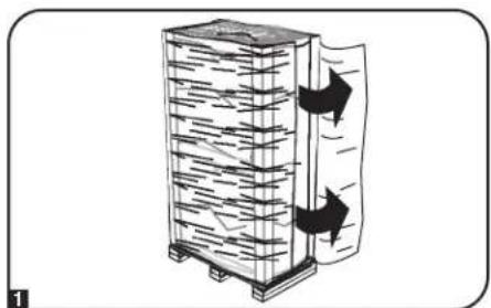
Unpacking
Note: If the enclosure is an "SP1" model with a shock pallet, follow the special unpacking instructions attached to the shipping container instead of the unpacking instructions in this section. All warnings still apply.
1 Confirm that the shipping container is upright and stable, then use a utility blade to cut the shrink-wrap securing the corner protectors. Apply the utility blade directly over the corner protectors to prevent the utility blade from scratching the enclosure or cutting the heavy protective plastic bag beneath the shrink-wrap. WARNING: Do not scratch the enclosure or cut the heavy plastic bag beneath the shrink-wrap. Do not push or pull the enclosure while unpacking.
2 Remove the corner protectors. Save all packing materials (including the pallet) for later use unless you are certain they will not be required. The packing materials are recyclable.
3 Remove the heavy plastic bag surrounding the enclosure. Examine the enclosure for any damage or loose parts. Confirm that all parts are present. If anything is missing or damaged, contact Tripp Lite for assistance. Do not attempt to use the enclosure if it has been damaged.
natural_image
Diagram of a vertical container with horizontal lines and arrows indicating flow or movement, no text or symbols present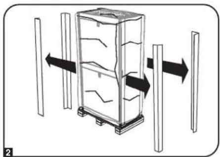
natural_image
Diagram of a refrigerator with directional arrows indicating movement or change, no text or symbols present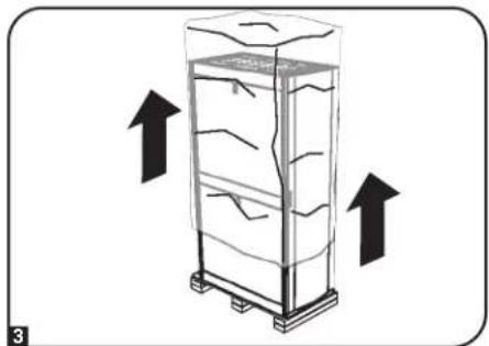
natural_image
Diagram of a refrigerator with upward arrows indicating airflow or movement (no text or symbols)Enclosure Installation
Unpacking (continued)
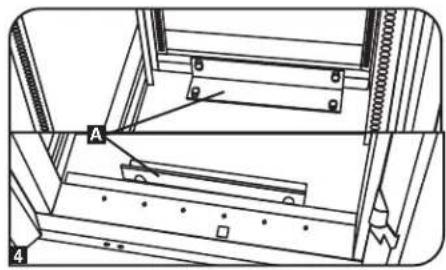
4 Use the key to open the enclosure's doors and locate the 2 shipping brackets A that attach the enclosure to the shipping pallet. The brackets are located inside the enclosure.
Note: The keys are attached to the front of the enclosure.
5 Use a 13 mm open-end wrench to remove the shipping brackets. Be extremely careful, as the enclosure could shift unexpectedly after bracket removal. Save the brackets and bracket hardware for later use.
6 Position at least one person at the front of the enclosure and one person at the rear of the enclosure. Slowly push the enclosure toward the back of the shipping pallet until all four casters go over the edge of the pallet and touch the floor. WARNING: Use at least one assistant when removing the enclosure from the pallet. Be extremely careful when moving the enclosure.
natural_image
Technical line drawing of a mechanical assembly with labeled component A (no text or symbols beyond label)
natural_image
Technical line drawing of a structural frame with hanging components and dashed alignment lines (no text or symbols)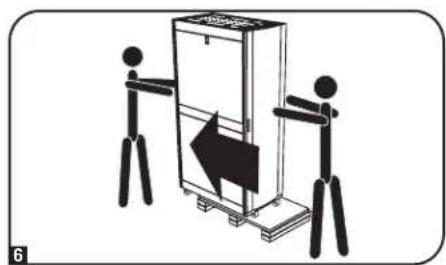
natural_image
Illustration of two stick figures pushing a box with a directional arrow (no text or symbols)Placement
1 Use the casters to move the enclosure for a short distance over a level, smooth, stable surface by pushing it from the front or rear (not the side panels). Do not attempt to roll the enclosure over long distances. The enclosure should be moved close to its installation location inside its shipping container before it is unpacked. (Use a forklift or pallet jack to move the shipping container.) WARNING: Do not push or pull the enclosure at the side panels or pull the enclosure toward you.
If required, the enclosure can be lifted by attaching 4 user-supplied M8 diameter eye bolts to the threaded holes near the upper corners of the enclosure frame. Use steel bolts with an ISO strength rating of 8.8 or higher. The 4 bolts can support the weight of the enclosure and up to 1000 lb (450 kg) of installed equipment. WARNING: Only experienced equipment operators should attempt to lift the enclosure. Use appropriate equipment and follow all applicable safety procedures and regulations.

natural_image
Illustration of a person standing beside a refrigerator with an arrow indicating left motion (no text or symbols)Enclosure Installation
Leveling
WARNING: Level the enclosure before attempting to install equipment. The casters are not designed to provide long-term support for the enclosure. Use the levelers to provide long-term support. Install the enclosure in a structurally sound area with a level floor that is able to bear the weight of the enclosure, all equipment that will be installed in the enclosure and any other enclosures and/or equipment that will be installed nearby.
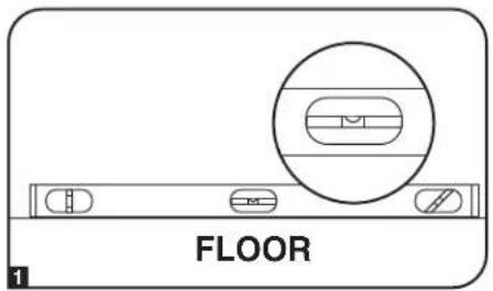
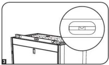
1 After the enclosure has been moved to the installation location, use a carpenter's level to check the slope of the floor. If the floor slopes more than 1%, choose an alternate installation site.
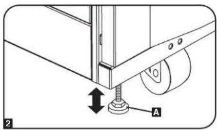
2 Use an 18 mm open-end wrench to lower each leveler A until it reaches the floor. (There are 4 levelers, 2 at the front and 2 at the rear.) Make sure each leveler contacts the floor solidly.
Note: Lower a leveler by turning it clockwise; raise a leveler by turning it counter-clockwise.
3 After lowering each leveler, use the carpenter's level to confirm that the enclosure is level in all directions. Adjust the levelers as required until the enclosure is level.
4 In order to secure the cabinet to the building structure for stability, attach the 2 shipping brackets using the hardware that attached the enclosure to the shipping pallet. Use a 13 mm open-end wrench to connect the brackets to the outer A or inner B bracket mounting points of the enclosure. Attach the brackets to secure mounting points in the floor using user-supplied hardware or Tripp Lite's SmartRack Bolt-Down Kit (Model: SRBOLTDOWN).
natural_image
Line drawing of a toolbox with a magnified inset showing internal components (no text or symbols)
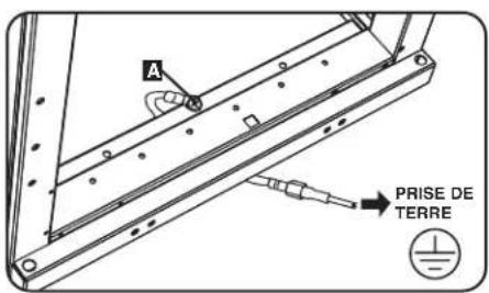
Ground Connection
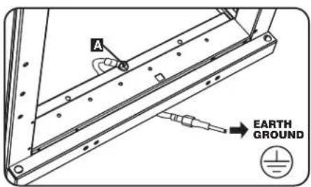
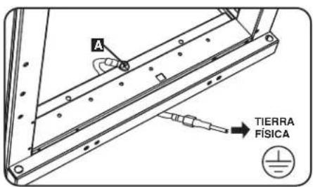
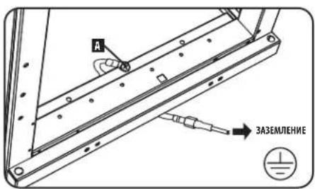
All the parts of the enclosure are grounded to the frame of the enclosure. Use the enclosure's front or rear threaded grounding point A and an M6 screw (included) to connect the frame of the enclosure directly to your facility's earth ground connection with an 8 AWG (3.264 mm) wire. Route the ground wire under the enclosure's frame to ensure unhindered door operation. WARNING: Attach each enclosure to earth ground separately. Do not use the enclosure without an earth ground connection.
Enclosure Configuration
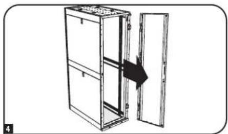
Adding or Removing Front and Rear Doors
WARNING: Do not attempt to add or remove doors without assistance.
Removing Door
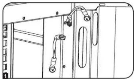
1 Disconnect the door's ground wire.
2 Open the door until it is perpendicular (90 degrees) to the front of the enclosure.
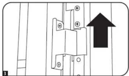
3 Lift the door from the hinges and remove it from the enclosure.
To Reinstall Door, Reverse Steps 1-3
(Optional) If the enclosure is joined to another enclosure, turn the door back toward the enclosure as you lift it from the hinges.
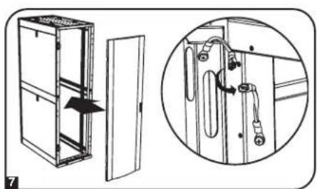
Reversing Front Door
WARNING: Do not attempt to reverse the front door without assistance.
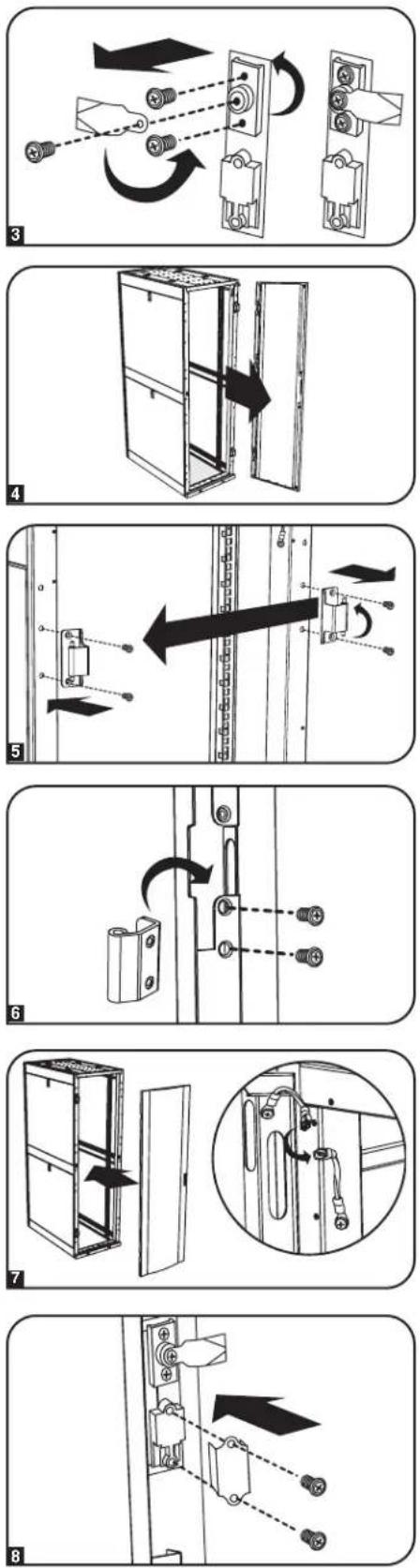
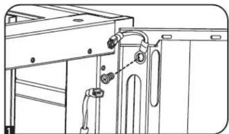
1 Remove the screw connecting the ground wire to the inside of the door.
2 Remove the 2 screws connecting the door handle to the door. Remove the door handle.
natural_image
Technical line drawing of a cabinet or enclosure with attached wiring and doors (no text or symbols)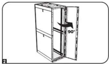
natural_image
Diagram of an open refrigerator with a 90-degree angle indicator (no text or symbols on the diagram itself)
natural_image
Pure electrical circuit lines without any symbols
natural_image
Technical line drawing of a kitchen appliance with attached fixtures and tubing (no text or symbols)
natural_image
Mechanical assembly diagram showing a bracket with mounting holes and a directional arrow (no text or symbols)Enclosure Configuration
Reversing Front Door (continued)
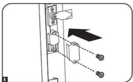
3 Remove the screw and washer from the rear of the door handle and remove the latching mechanism. Rotate the latch washer counter-clockwise 90 degrees and reverse the latch so it points in the opposite direction, then use the screw and washer to re-attach the latch to the rear of the door handle.
4 Remove the door by following the steps in the previous section.
5 Remove the door hinges from the enclosure, rotate them 180 degrees and attach them on the opposite side of the enclosure. Note: The alternate door hinge attachment points have plastic plugs in the screw holes. Remove the plugs and insert them in the original door hinge attachment points.
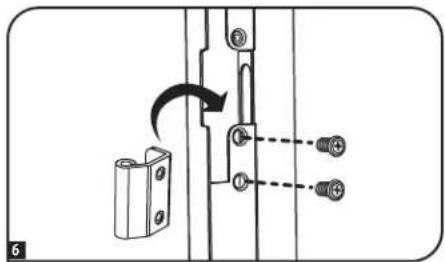
6 Unscrew the 2 hinge mechanisms from the hinge openings inside the door, then reattach each of them using the set of screw holes immediately opposite their original position.
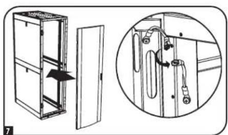
7 Rotate the door 180 degrees and reinstall it on the enclosure. Remember to connect the ground wire to the inside of the door, using the attachment point nearest the hinge at the top of the door. The attachment point is marked with the ground connection symbol:
8 Reinstall the door handle.
Enclosure Configuration
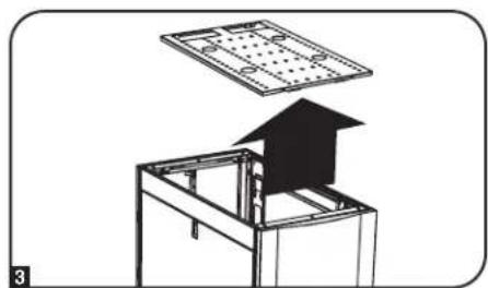
Adding or Removing Roof Panel
WARNING: Do not attempt to use the roof panel for weight-bearing purposes other than those explicitly described and approved by Tripp Lite. Do not attempt to add or remove the roof panel without assistance.
Removing Roof Panel
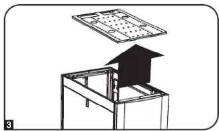
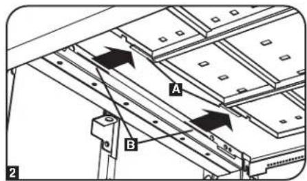
1 Pull the 2 pins near the rear of the roof panel. While holding the pins, push the roof panel upward.
2 Remove the roof panel tabs A from the roof panel attachment slots B in the enclosure frame.
3 Lift the roof panel from the enclosure.
To Reinstall Roof Panel, Reverse Steps 1-3
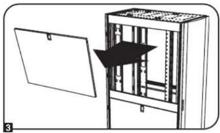
Adding or Removing Side Panels Removing Side Panel
1 Open the latch by sliding it downward.
2 Tilt the top of the panel away from the enclosure.


natural_image
Diagram of a house inside a metal enclosure with an open roof, showing structural components (no text or symbols)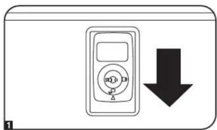
natural_image
Simple line drawing of a device with a circular dial and downward arrow (no text or symbols)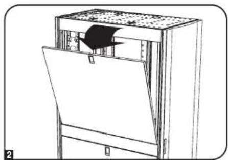
natural_image
Line drawing of a mechanical device with a door and internal panel (no text or symbols)Enclosure Configuration
Adding or Removing Side Panels (continued)
3 Lift the panel away from the brace that supports it.
To Reinstall Side Panel, Reverse Steps 1-3
natural_image
Diagram of a server rack unit with an open panel and a black arrow indicating direction (no text or symbols present)Adjusting Mounting Rails and Cable Management Rails
WARNING: Do not attempt to adjust rails without assistance. Do not attempt to adjust rails while equipment is installed in the enclosure. Do not attempt to use rails without screws installed (6 per rail).
The 4 mounting rails are pre-installed to accommodate equipment with a mounting depth of 30 inches (762 mm). Do not adjust the mounting rails unless your equipment requires a different mounting depth. The front and rear sets of rails can be adjusted independently in 14 -inch (6 mm) increments for mounting depths between 4 inches (101.6 mm) and 42 inches (1066.8 mm).
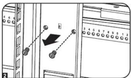
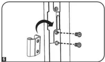
1 Each rail is connected to the enclosure with 6 screws - 1 pair at the upper beam A, 1 pair at the middle beam B and 1 pair at the lower beam C.
2 Remove the screws fastening each of the rear mounting rails to the enclosure. (If adjustment of the front rails is required, you can also remove the screws from the front rails.)
3 Slide the mounting rails to the desired depth and reattach them using the screws you removed in Step 2. The rail attachment points are numbered A to help you align each pair of rails at the same depth.
The depth of the 2 cable management rails can be adjusted using the same method.
Enclosure Configuration
Combining (Baying) Enclosures
WARNING: Combining enclosures is not a substitute for stabilizing the enclosures. Each enclosure in a bay of combined enclosures requires the same stabilizing measures as a standalone enclosure.
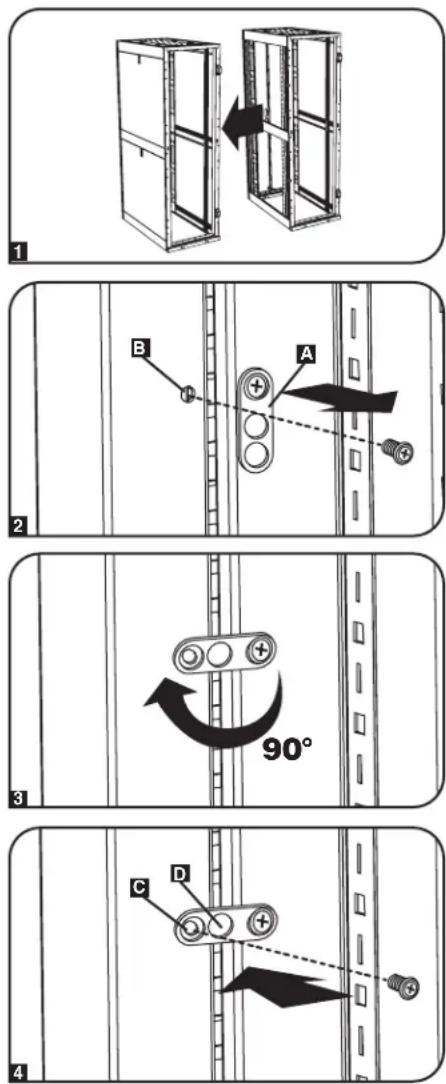
1 Arrange the enclosures in the correct position for baying.
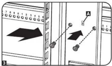
2 Each enclosure includes 4 baying brackets A that correspond to baying connection points B on the adjoining enclosure. The baying connection points already contain screws. Remove the screw from each baying connection point in the adjoining enclosure.
3 Loosen the screw in each baying bracket and turn each bracket 90 degrees toward the adjoining enclosure, aligning each bracket with the corresponding baying connection point on the adjoining enclosure.
4 Connect each bracket to the adjoining enclosure using the screws you removed in step 2, but do not tighten the screws completely. Adjust the position of the enclosures as needed. If you want the centers of the enclosures to be 24 inches (61 cm) apart/29.9 inches (76 cm) for the SR42UBWD, use the outside hole of the bracket C. If you want the centers to be 60 cm (23.6 inches) apart/75 cm (29.5 inches) for the SR42UBWD, use the middle hole of the bracket D. After connecting all brackets and confirming that the enclosures do not need further adjustment, tighten all screws.
Note: You may wish to remove the doors from the enclosures before combining them. Reinstalling the doors afterward is optional. Remove the interior side panels before baying enclosures if you wish to enable access between enclosures.
Equipment Installation
WARNING: Do not install equipment until you have stabilized the enclosure. Install heavier equipment first and install it toward the bottom of the enclosure. Install equipment starting from the bottom of the enclosure and proceeding toward the top of the enclosure - never the reverse. If using sliding equipment rails, be careful when extending the rails. Do not extend more than one set of sliding equipment rails at one time. Avoid extending sliding equipment rails near the top of the enclosure.
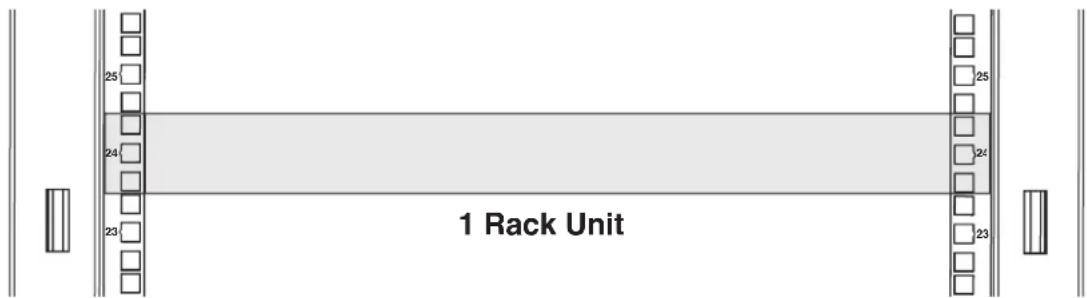
Note: The square holes at the middle of each rack unit are numbered and also include a small notch to aid identification. A single rack unit includes the space occupied by the numbered hole and the holes directly above and below.
Equipment Installation
Installing or Removing Cage Nuts
WARNING: The flanges of the cage nuts should engage the sides of the square opening in the rail, not the top and bottom. Follow the instructions in your equipment documentation to ensure proper installation of your equipment.
Installing Cage Nuts
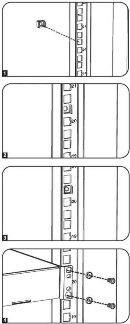
1 Locate the numbered square openings in the mounting rails where you plan to install your equipment. You will install cage nuts (included) into the square openings in order to provide an attachment point for the mounting screws (included).
Note: Consult your equipment documentation to determine how many cage nuts will be required and where they will need to be installed.
2 From the inside of the mounting rail, insert one of the flanges of the cage nut through the square opening. Press it against the side of the square opening. Each flange should engage one side of the square opening, not the top or bottom.
3 Compress the cage nut at the sides slightly to allow the remaining flange to fit through the square opening. When the cage nut is properly installed, both flanges will protrude through the square opening and will be visible on the outer surface of the mounting rail. Repeat steps 1-3 until all required cage nuts are installed.
4 After installing the required cage nuts, use the included mounting screws and cup washers to secure your equipment to the rack rail. Place the cup washers between the screws and the equipment mounting brackets.
Note: Your equipment may also include mounting hardware. Read the mounting instructions that came with your equipment before installing your equipment.
To Remove Cage Nuts, Reverse Steps 1-3
Note: You may wish to use a cage nut tool (user-supplied) to aid cage nut installation and removal.
Specifications
| Model Static Ro | Load Capacity* Unit Dimensions Shipping Dimensions | |||||||||
| Holding Height Width Depth Weight Height Width Depth Weight | ||||||||||
| SR24UB 3000 lb. | (1363 kg) | 2250 lb.(1022 kg) | 47.25 in.(1200 mm) | 23.63 in.(600 mm) | 43 in.(1092 mm) | 190 lb.(86 kg) | 51.4 in.(1306 mm) | 26 in.(660 mm) | 45 in.(1140 mm) | 232 lb.(105 kg) |
| SR24UBEXP 3000 lb. | (1363 kg) | 2250 lb.(1022 kg) | 47.25 in.(1200 mm) | 23.63 in.(600 mm) | 43 in.(1092 mm) | 145 lb.(66 kg) | 51.4 in.(1306 mm) | 26 in.(660 mm) | 45 in.(1140 mm) | 187 lb.(85 kg) |
| SR24UBSP1 3000 lb. | (1363 kg) | 2250 lb.(1022 kg) | 47.25 in.(1200 mm) | 23.63 in.(600 mm) | 43 in.(1092 mm) | 190 lb.(86 kg) | 51.4 in.(1306 mm) | 28 in.(705 mm) | 47 in.(1194 mm) | 240 lb.(109 kg) |
| SR24UBEXPSP1 3000 lb. | (1363 kg) | 2250 lb.(1022 kg) | 47.25 in.(1200 mm) | 23.63 in.(600 mm) | 43 in.(1092 mm) | 145 lb.(66 kg) | 51.4 in.(1306 mm) | 28 in.(705 mm) | 47 in.(1194 mm) | 195 lb.(88 kg) |
| SR25UB 3000 lb. | (1363 kg) | 2250 lb.(1022 kg) | 49.00 in.(1245 mm) | 23.63 in.(600 mm) | 43 in.(1092 mm) | 195 lb.(88.6 kg) | 53.5 in.(1358.9 mm) | 24 in.(609.6 mm) | 43.0 in.(1092.2 mm) | 237.0 lb.(107.5 kg) |
| SR42UB 3000 lb. | (1363 kg) | 2250 lb.(1022 kg) | 78.5 in.(1994 mm) | 23.63 in.(600 mm) | 43 in.(1092 mm) | 286 lb.(130 kg) | 85 in.(2149 mm) | 26 in.(660 mm) | 45 in.(1140 mm) | 328 lb.(149 kg) |
Specifications
Load Capacity* Unit Dimensions Shipping Dimensions
| Model Static Rolling Height Width Depth Weight Height Width Depth Weight | ||||||||||
| SRX42UB** 3000 lb. (1363 kg) | 2250 lb. (1022 kg) | 78.5 in. (1994 mm) | 23.63 in. (600 mm) | 41.25 in. (1048 mm) | 298.98 lb. (135.62 kg) | 83.43 in. (2118 mm) | 25.75 in. (654 mm) | 42.85 in. (1088.4 mm) | 331.06 lb. (150.17 kg) | |
| SR42UBCL 3000 lb. (1363 kg) | 2250 lb. (1022 kg) | 78.5 in. (1994 mm) | 23.63 in. (600 mm) | 43 in. (1092 mm) | 305 lb. (138 kg) | 85 in. (2149 mm) | 26 in. (660 mm) | 45 in. (1140 mm) | 347 lb. (157 kg) | |
| SR42UBDP 3000 lb. (1363 kg) | 2250 lb. (1022 kg) | 78.5 in. (1994 mm) | 23.63 in. (600 mm) | 47.3 in. (1200 mm) | 315 lb. (143 kg) | 85 in. (2149 mm) | 26 in. (660 mm) | 50.72 in. (1288.4 mm) | 367 lb. (167 kg) | |
| SR42UBDP** 3000 lb. (1363 kg) | 2250 lb. (1022 kg) | 78.5 in. (1994 mm) | 23.63 in. (600 mm) | 49 in. (1246 mm) | 323.20 lb. (146.60 kg) | 83.43 in. (2118 mm) | 25.75 in. (654 mm) | 50.72 in. (1288.4 mm) | 358.74 lb. (162.72 kg) | |
| SR42UBDPEXP** 3000 lb. (1363 kg) | 2250 lb. (1022 kg) | 78.5 in. (1994 mm) | 23.63 in. (600 mm) | 49 in. (1246 mm) | 234.51 lb. (106.37 kg) | 83.43 in. (2118 mm) | 25.75 in. (654 mm) | 50.72 in. (1288.4 mm) | 270.05 lb. (122.49 kg) | |
| SR42UBDPWD 3000 lb. (1363 kg) | 2250 lb. (1022 kg) | 78.5 in. (1994 mm) | 29.53 in. (750 mm) | 47.3 in. (1200 mm) | 342 lb. (155 kg) | 85 in. (2149 mm) | 26 in. (660 mm) | 50.72 in. (1288.4 mm) | 404 lb. (183 kg) | |
| SR42UBDPWD** 3000 lb. (1363 kg) | 2250 lb. (1022 kg) | 78.5 in. (1994 mm) | 31.5 in. (800 mm) | 49 in. (1246 mm) | 374.58 lb. (169.91 kg) | 83.43 in. (2118 mm) | 33.46 in. (850 mm) | 50.72 in. (1288.4 mm) | 422.55 lb. (191.65 kg) | |
| SR42UBDPWDEXP** 3000 lb. (1363 kg) | 2250 lb. (1022 kg) | 78.5 in. (1994 mm) | 31.5 in. (800 mm) | 49 in. (1246 mm) | 285.27 lb. (129.39 kg) | 83.43 in. (2118 mm) | 33.46 in. (850 mm) | 50.72 in. (1288.4 mm) | 333.23 lb. (151.15 kg) | |
| SR42UBEXP 3000 lb. (1363 kg) | 2250 lb. (1022 kg) | 78.5 in. (1994 mm) | 23.63 in. (600 mm) | 43 in. (1092 mm) | 209 lb. (95 kg) | 85 in. (2149 mm) | 26 in. (660 mm) | 45 in. (1140 mm) | 251 lb. (114 kg) | |
| SR42UBEXP** 3000 lb. (1363 kg) | 2250 lb. (1022 kg) | 78.5 in. (1994 mm) | 23.63 in. (600 mm) | 41.25 in. (1048 mm) | 224.75 lb. (101.94 kg) | 83.43 in. (2118 mm) | 25.75 in. (654 mm) | 42.85 in. (1088.4 mm) | 256.82 lb. (116.50 kg) | |
| SR42UBEXPND 3000 lb. (1363 kg) | 2250 lb. (1022 kg) | 78.5 in. (2261 mm) | 23.63 in. (600 mm) | 43 in. (1092 mm) | 161 lb. (73.03 kg) | 84 in. (2133.6 mm) | 28 in. (711.2 mm) | 47 in. (1193.8 mm) | 211 lb. (95.7 kg) | |
| SR42UBEXPSP1 3000 lb. (1363 kg) | 2250 lb. (1022 kg) | 78.5 in. (1994 mm) | 23.63 in. (600 mm) | 43 in. (1092 mm) | 203 lb. (92 kg) | 84 in. (2146 mm) | 28 in. (705 mm) | 47 in. (1194 mm) | 253 lb. (115 kg) | |
| SR42UBSP1 3000 lb. (1363 kg) | 2250 lb. (1022 kg) | 78.5 in. (1994 mm) | 23.63 in. (600 mm) | 43 in. (1092 mm) | 286 lb. (130 kg) | 84 in. (2146 mm) | 28 in. (705 mm) | 47 in. (1194 mm) | 336 lb. (152 kg) | |
| SR42UBWD 3000 lb. (1363 kg) | 2250 lb. (1022 kg) | 78.5 in. (1994 mm) | 29.53 in. (750 mm) | 43 in. (1092 mm) | 313 lb. (142 kg) | 85 in. (2149 mm) | 26 in. (660 mm) | 45 in. (1140 mm) | 365 lb. (166 kg) | |
| SR42UBWD** 3000 lb. (1363 kg) | 2250 lb. (1022 kg) | 78.5 in. (1994 mm) | 31.5 in. (800 mm) | 41.25 in. (1048 mm) | 349.53 lb. (158.55 kg) | 83.43 in. (2118 mm) | 33.46 in. (850 mm) | 42.85 in. (1088.4 mm) | 392.72 lb. (178.14 kg) | |
| SR42UBWDEXP** 3000 lb. (1363 kg) | 2250 lb. (1022 kg) | 78.5 in. (1994 mm) | 31.5 in. (800 mm) | 41.25 in. (1048 mm) | 275.30 lb. (124.87 kg) | 83.43 in. (2118 mm) | 33.46 in. (850 mm) | 42.85 in. (1088.4 mm) | 318.49 lb. (144.46 kg) | |
| SR42UBWDCL 3000 lb. (1363 kg) | 2250 lb. (1022 kg) | 78.5 in. (1994 mm) | 29.53 in. (750 mm) | 43 in. (1092 mm) | 304 lb. (138 kg) | 85 in. (2149 mm) | 26 in. (660 mm) | 45 in. (1140 mm) | 346 lb. (157 kg) | |
| SR45UB 3000 lb. (1363 kg) | 2250 lb. (1022 kg) | 84 in. (2133.6 mm) | 23.63 in. (600 mm) | 43 in. (1092 mm) | 305 lb. (138 kg) | 92.5 in. (2298.7 mm) | 26 in. (660 mm) | 45 in. (1140 mm) | 347 lb. (157 kg) | |
| SR47UB** 3000 lb. (1363 kg) | 2250 lb. (1022 kg) | 87.2 in. (2215 mm) | 23.63 in. (600 mm) | 41.25 in. (1048 mm) | 326.23 lb. (147.98 kg) | 87.2 in. (2215 mm) | 25.75 in. (654 mm) | 42.85 in. (1088.4 mm) | 358.31 lb. (162.53 kg) | |
| SR47UBEXP** 3000 lb. (1363 kg) | 2250 lb. (1022 kg) | 87.2 in. (2215 mm) | 23.63 in. (600 mm) | 41.25 in. (1048 mm) | 326.23 lb. (147.98 kg) | 87.2 in. (2118 mm) | 25.75 in. (654 mm) | 42.85 in. (1088.4 mm) | 358.31 lb. (162.53 kg) | |
| SR47UBDP** 3000 lb. (1363 kg) | 2250 lb. (1022 kg) | 87.2 in. (2215 mm) | 23.63 in. (600 mm) | 49 in. (1246 mm) | 242.90 lb. (110.18 kg) | 87.2 in. (2215 mm) | 25.75 in. (654 mm) | 50.72 in. (1288.4 mm) | 274.98 lb. (124.73 kg) | |
| SR47UBDPEXP** 3000 lb. (1363 kg) | 2250 lb. (1022 kg) | 87.2 in. (2215 mm) | 23.63 in. (600 mm) | 49 in. (1246 mm) | 352.29 lb. (159.80 kg) | 87.2 in. (2215 mm) | 25.75 in. (654 mm) | 50.72 in. (1288.4 mm) | 387.83 lb. (175.92 kg) | |
| SR47UBWD** 3000 lb. (1363 kg) | 2250 lb. (1022 kg) | 87.2 in. (2215 mm) | 23.63 in. (600 mm) | 49 in. (1246 mm) | 252.04 lb. (114.33 kg) | 87.2 in. (2215 mm) | 25.75 in. (654 mm) | 50.72 in. (1288.4 mm) | 287.58 lb. (130.45 kg) | |
| SR47UBWDEXP** 3000 lb. (1363 kg) | 2250 lb. (1022 kg) | 87.2 in. (2215 mm) | 31.5 in. (800 mm) | 41.25 in. (1048 mm) | 381.42 lb. (173.01 kg) | 87.2 in. (2215 mm) | 33.46 in. (850 mm) | 42.85 in. (1088.4 mm) | 424.60 lb. (192.60 kg) | |
| SR47UBDPWD** 3000 lb. (1363 kg) | 2250 lb. (1022 kg) | 87.2 in. (2215 mm) | 31.5 in. (800 mm) | 49 in. (1246 mm) | 298.09 lb. (135.21 kg) | 87.2 in. (2215 mm) | 33.46 in. (850 mm) | 50.72 in. (1288.4 mm) | 341.27 lb. (154.80 kg) | |
| SR47UBDPWDEXP** 3000 lb. (1363 kg) | 2250 lb. (1022 kg) | 87.2 in. (2215 mm) | 31.5 in. (800 mm) | 49 in. (1246 mm) | 408.30 lb. (185.20 kg) | 87.2 in. (2215 mm) | 33.46 in. (850 mm) | 50.72 in. (1288.4 mm) | 456.27 lb. (206.96 kg) | |
| SR48UB 3000 lb. (1363 kg) | 2250 lb. (1022 kg) | 89 in. (2261 mm) | 23.63 in. (600 mm) | 43 in. (1092 mm) | 315 lb. (143 kg) | 95 in. (2416 mm) | 26 in. (660 mm) | 45 in. (1140 mm) | 357 lb. (162 kg) | |
| SR48UBCL 3000 lb. (1363 kg) | 2250 lb. (1022 kg) | 89 in. (2261 mm) | 23.63 in. (600 mm) | 43 in. (1092 mm) | 334 lb. (151 kg) | 95 in. (2416 mm) | 26 in. (660 mm) | 45 in. (1140 mm) | 376 lb. (171 kg) | |
| SR48UBDPWD 3000 lb. (1363 kg) | 2250 lb. (1022 kg) | 89 in. (2261 mm) | 29.53 in. (750 mm) | 47.3 in. (1200 mm) | 378 lb. (171.5 kg) | 26 in. (660 mm) | 45 in. (1143 mm) | 53 in. (1340 mm) | 440 lb. (200 kg) | |
| SR48UBEXP 3000 lb. (1363 kg) | 2250 lb. (1022 kg) | 89 in. (2261 mm) | 23.63 in. (600 mm) | 43 in. (1092 mm) | 225 lb. (102 kg) | 95 in. (2416 mm) | 26 in. (660 mm) | 45 in. (1140 mm) | 267 lb. (121 kg) | |
| SR48UBEXPSP1 3000 lb. (1363 kg) | 2250 lb. (1022 kg) | 89 in. (2261 mm) | 23.63 in. (600 mm) | 43 in. (1092 mm) | 225 lb. (102 kg) | 95 in. (2416 mm) | 26 in. (705 mm) | 47 in. (1194 mm) | 213 lb. (96.6 kg) | |
| SR48UBSP1 3000 lb. (1363 kg) | 2250 lb. (1022 kg) | 89 in. (2261 mm) | 23.63 in. (600 mm) | 43 in. (1092 mm) | 315 lb. (143 kg) | 95 in. (2416 mm) | 26 in. (660mm) | 45 in. (1143 mm) | 365 lb. (166 kg) | |
| SR48UBWD 3000 lb. (1363 kg) | 2250 lb. (1022 kg) | 89 in. (2261 mm) | 29.53 in. (750 mm) | 43 in. (1092 mm) | 343 lb. (156 kg) | 95 in. (2416 mm) | 26 in. (660 mm) | 45 in. (1140 mm) | 395 lb. (179 kg) | |
| SR50UB 3000 lb. (1363 kg) | 2250 lb. (1022 kg) | 93 in. (2323 mm) | 23.63 in. (600 mm) | 43 in. (1092 mm) | 347 lb. (157.5 kg) | 98 in. (2489 mm) | 26 in. (660 mm) | 45 in. (1140 mm) | 400 lb. (182 kg) | |
| SR52UB 3000 lb. (1363 kg) | 2250 lb. (1022 kg) | 96 in. (2443 mm) | 23.63 in. (600 mm) | 43 in. (1092 mm) | 358.5 lb. (163 kg) | 101 in. (2570 mm) | 26 in. (660 mm) | 45 in. (1140 mm) | 413 lb. (187 kg) | |
| SR52UBDP 3000 lb. (1363 kg) | 2250 lb. (1022 kg) | 96 in. (2443 mm) | 23.63 in. (600 mm) | 47.3 in. (1200 mm) | 379 lb. (172 kg) | 101 in. (2570 mm) | 33.5 in. (850 mm) | 49.75 in. (1264 mm) | 449 lb. (204 kg) | |
| SR55UB 3000 lb. (1363 kg) | 2250 lb. (1022 kg) | 101.5 in. (2577 mm) | 23.63 in. (600 mm) | 43 in. (1092 mm) | 375 lb. (170 kg) | 106.5 in. (2703 mm) | 26 in. (660 mm) | 45 in. (1140 mm) | 431 lb. (195 kg) | |
**SP1* models include a shock pallet that allows the enclosure to be shipped with pre-installed equipment. The maximum shipping capacity is 1250 lb (568 kg), including the weight of the enclosure and the pre-installed equipment. **SRX-Series SmartRack Enclosure
Storage and Service
Storage
The enclosure should be stored in a controlled indoor environment, away from moisture, temperature extremes, flammable liquids and gasses, conductive contaminants, dust and direct sunlight. Store the enclosure in its original shipping container if possible.
Service
Your Tripp Lite product is covered by the warranty described in this manual. A variety of Extended Warranty and On-Site Service Programs are also available from Tripp Lite. For more information on service, visit tripplite.com/support. Before returning your product for service, follow these steps:
- Review the installation and operation procedures in this manual to insure that the service problem does not originate from a misreading of the instructions.
- If the problem continues, do not contact or return the product to the dealer. Instead, visit tripplite.com/support.
- If the problem requires service, visit triplite.com/support and click the Product Returns link. From here you can request a Returned Material Authorization (RMA) number, which is required for service. This simple on-line form will ask for your unit's model and serial numbers, along with other general purchaser information. The RMA number, along with shipping instructions will be emailed to you. Any damages (direct, indirect, special or consequential) to the product incurred during shipment to Tripp Lite or an authorized Tripp Lite service center is not covered under warranty. Products shipped to Tripp Lite or an authorized Tripp Lite service center must have transportation charges prepaid. Mark the RMA number on the outside of the package. If the product is within its warranty period, enclose a copy of your sales receipt. Return the product for service using an insured carrier to the address given to you when you request the RMA.
Warranty and Product Registration
5-Year Limited Warranty
Seller warrants this product, if used in accordance with all applicable instructions, to be free from original defects in material and workmanship for a period of 5 years from the date of initial purchase. If the product should prove defective in material or workmanship within that period, Seller will repair or replace the product, in its sole discretion.
THIS WARRANTY DOES NOT APPLY TO NORMAL WEAR OR TO DAMAGE RESULTING FROM ACCIDENT, MISUSE, ABUSE OR NEGLECT. SELLER MAKES NO EXPRESS WARRANTIES OTHER THAN THE WARRANTY EXPRESSLY SET FORTH HEREIN. EXCEPT TO THE EXTENT PROHIBITED BY APPLICABLE LAW, ALL IMPLIED WARRANTIES, INCLUDING ALL WARRANTIES OF MERCHANTABILITY OR FITNESS, ARE LIMITED IN DURATION TO THE WARRANTY PERIOD SET FORTH ABOVE; AND THIS WARRANTY EXPRESSLY EXCLUDES ALL INCIDENTAL AND CONSEQUENTIAL DAMAGES. (Some states do not allow limitations on how long an implied warranty lasts, and some states do not allow the exclusion or limitation of incidental or consequential damages, so the above limitations or exclusions may not apply to you. This warranty gives you specific legal rights, and you may have other rights which vary from jurisdiction to jurisdiction).
WARNING: The individual user should take care to determine prior to use whether this device is suitable, adequate or safe for the use intended. Since individual applications are subject to great variation, the manufacturer makes no representation or warranty as to the suitability or fitness of these devices for any specific application.
Product Registration
Visit triplite.com/warranty today to register your new Tripp Lite product. You'll be automatically entered into a drawing for a chance to win a FREE Tripp Lite product!*
* No purchase necessary. Void where prohibited. Some restrictions apply. See Web site for details.
Tripp Lite follows a policy of continuous improvement. Product specifications are subject to change without notice. Photos and illustrations may differ slightly from actual products.
Note on Labeling
This symbol is used on the product: Ground Connection


1111 W. 35th Street, Chicago, IL 60609 USA • tripplite.com/support
21-12-060 93-2723_RevJ
1111 W. 35th Street, Chicago, IL 60609 USA • tripplite.com/support
natural_image
Diagram of a vertical container with horizontal lines and arrows indicating flow or movement, no text or symbols present
natural_image
Diagram of a refrigerator with directional arrows indicating movement or change, no text or symbols present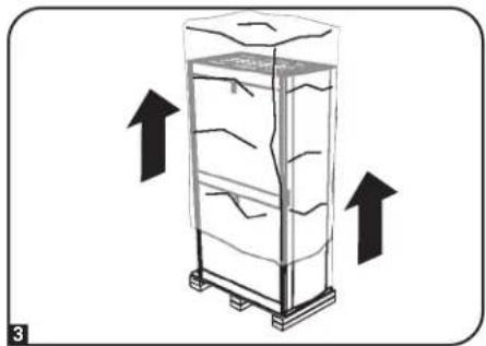
natural_image
Diagram of a refrigerator with upward arrows indicating airflow or movement (no text or symbols)natural_image
Technical line drawing of a mechanical assembly with labeled components (no text or symbols)
natural_image
Technical line drawing of a structural frame with hanging components and dashed alignment lines (no text or symbols)
natural_image
Illustration of two stick figures pushing a box with a directional arrow (no text or symbols)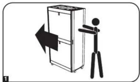
natural_image
Illustration of a person standing beside a refrigerator with an arrow indicating left motion (no text or symbols)natural_image
Line drawing of a briefcase with a magnified inset showing internal components (no text or symbols)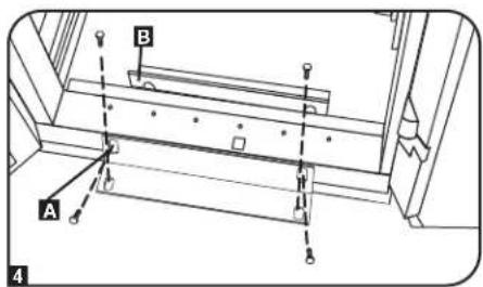
natural_image
Technical line drawing of a cabinet or enclosure with attached wiring and doors (no text or symbols)
natural_image
Diagram of a refrigerator with an open door and 90-degree angle indicator (no text or symbols)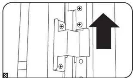
natural_image
Pure electrical circuit lines without any symbols
natural_image
Technical line drawing of a kitchen appliance with attached fixtures and tubing (no text or symbols)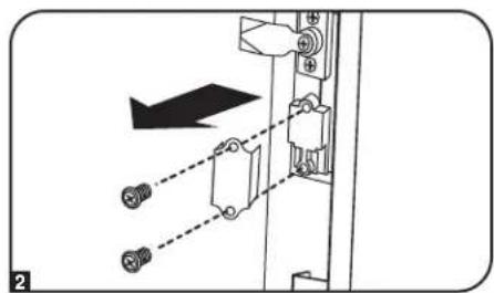
natural_image
Mechanical assembly diagram showing a bracket with mounting holes and a directional arrow (no text or symbols)
natural_image
Diagram of a cabinet with an open door and internal structure, showing no text or symbols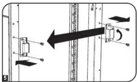


natural_image
Diagram of a house inside a metal enclosure with an open roof, showing structural components (no text or symbols)natural_image
Simple line drawing of a device with a circular dial and downward arrow (no text or symbols)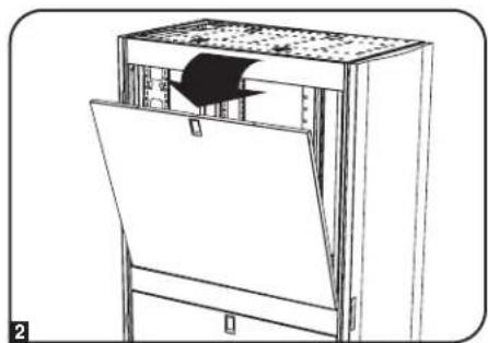
natural_image
Line drawing of a mechanical device with a door and internal panel, no text or symbols presentnatural_image
Diagram of a server rack unit with an open panel and a black arrow indicating direction (no text or symbols present)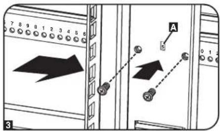
1111 W. 35th Street, Chicago, IL 60609 USA • triplite.com/support
21-12-060 93-2723_RevJ
1111 W. 35th Street, Chicago, IL 60609 USA • tripplite.com/support
Entreposage et service.
natural_image
Diagram of a vertical storage unit with internal flow arrows indicating material movement (no text or symbols)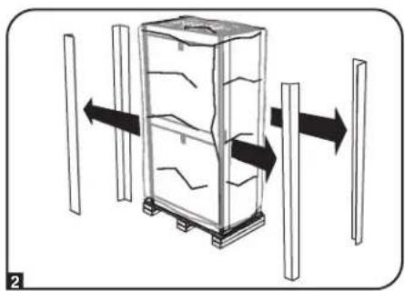
natural_image
Diagram of a refrigerator with directional arrows indicating movement or change, no text or symbols present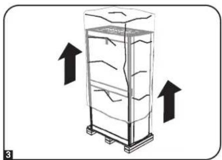
natural_image
Illustration of a refrigerator with upward arrows indicating airflow or movement (no text or symbols)natural_image
Technical line drawing of a mechanical assembly with labeled components (no text or symbols)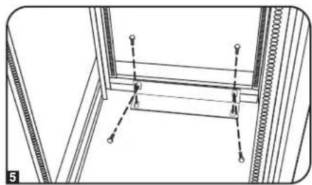
natural_image
Technical line drawing of a structural frame with hanging components and dashed alignment lines (no text or symbols)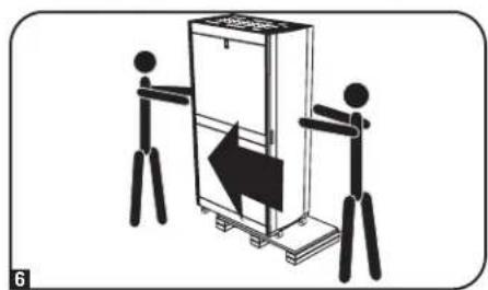
natural_image
Illustration of two stick figures pushing a large box with a directional arrow (no text or symbols)
natural_image
Illustration of a person using a walking stick to lift a refrigerator with an arrow indicating left motion (no text or symbols)natural_image
Line drawing of a briefcase with a magnified inset showing internal components (no text or symbols)
natural_image
Technical line drawing of a cabinet or enclosure with attached wiring and doors (no text or symbols)
natural_image
Diagram of an open refrigerator with a 90-degree angle indicator (no text or symbols on the diagram itself)
natural_image
Pure electrical circuit lines without any symbols
natural_image
Technical line drawing of a kitchen appliance with attached fixtures and tubing (no text or symbols)
natural_image
Mechanical assembly diagram showing a bracket with mounting holes and a directional arrow (no text or symbols)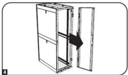
natural_image
Diagram of a cabinet with an open door and internal structure, showing no text or symbols


natural_image
Diagram of a house inside a metal enclosure with an open roof, showing structural components (no text or symbols)natural_image
Simple line drawing of a device with a circular dial and downward arrow (no text or symbols)
natural_image
Line drawing of a mechanical device with a door and internal panel, no text or symbols presentnatural_image
Diagram of a server rack unit with an open panel and directional arrow indicating movement (no text or symbols)
1111 W. 35th Street, Chicago, IL 60609 USA • tripplite.com/support
1111 W. 35th Street, Chicago, IL 60609 USA • tripplite.com/support
natural_image
Diagram of a vertical stacker with horizontal lines and arrows indicating flow or movement, no text or symbols present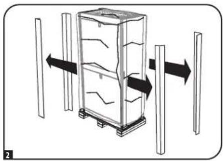
natural_image
Diagram of a refrigerator with directional arrows indicating movement or change, no text or symbols present
natural_image
Diagram of a refrigerator with upward arrows indicating airflow or movement (no text or symbols)natural_image
Technical line drawing of a mechanical assembly with labeled component A (no text or symbols present)
natural_image
Technical line drawing of a structural frame with hanging components and dashed alignment lines (no text or symbols)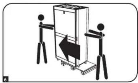
natural_image
Illustration of two stick figures pushing a box with an arrow, no text or symbols present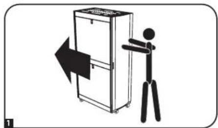
natural_image
Illustration of a person pushing a refrigerator with a directional arrow (no text or symbols)natural_image
Line drawing of a toolbox with a magnified inset showing internal components (no text or symbols)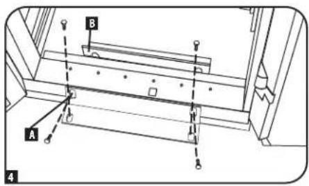
Компоновка шкафа
natural_image
Technical line drawing of a cabinet or enclosure with connectors and doors (no text or symbols)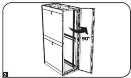
natural_image
Technical line drawing of a kitchen appliance with handlebars and doors (no text or symbols)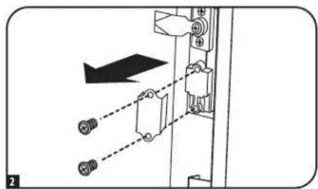
natural_image
Diagram of a mechanical assembly with two screws and a directional arrow (no text or symbols)Компоновка шкафа
natural_image
Diagram of a cabinet with an open door and internal structure, showing no text or symbols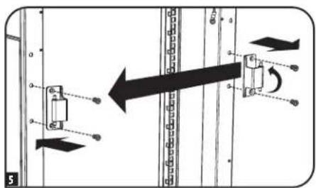
Компоновка шкафа
natural_image
Diagram of a house inside a metal enclosure with a roof structure above (no text or symbols)natural_image
Simple line drawing of a device with a circular dial and downward arrow (no text or symbols)natural_image
Line drawing of a cabinet with an open lid and a black arrow pointing to the door (no text or symbols)Компоновка шкафа
natural_image
Diagram of a server rack unit with an open panel and a black arrow indicating direction (no text or symbols)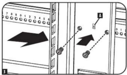
Компоновка шкафа

1111 W. 35th Street, Chicago, IL 60609 USA · tripplite.com/support
21-12-060 93-2723 Rev
- SmartRack® Enclosures
- Important Safety Instructions 2
- WARRANTY REGISTRATION
- Important Safety Instructions
- SAVE THESE INSTRUCTIONS
- Overview
- Feature Identification
- Enclosure Installation
- Caution! Read All Instructions and Warnings Before Installation!
- Preparation
- Unpacking
- Unpacking (continued)
- Placement
- Leveling
- Ground Connection
- Enclosure Configuration
- Adding or Removing Front and Rear Doors
- Removing Door
- To Reinstall Door, Reverse Steps 1-3
- Reversing Front Door
- Reversing Front Door (continued)
- Adding or Removing Roof Panel
- Removing Roof Panel
- Adding or Removing Side Panels Removing Side Panel
- Adding or Removing Side Panels (continued)
- To Reinstall Side Panel, Reverse Steps 1-3
- Adjusting Mounting Rails and Cable Management Rails
- Combining (Baying) Enclosures
- Equipment Installation
- Installing or Removing Cage Nuts
- Installing Cage Nuts
- To Remove Cage Nuts, Reverse Steps 1-3
- Specifications
- Storage and Service
- Storage
- Service
- Warranty and Product Registration
- 5-Year Limited Warranty
- Product Registration
- Note on Labeling
- Entreposage et service.
- Компоновка шкафа
Brand : Tripp Lite
Model : SmartRack SR42UWSP1
Category : Server rack