
Swimspa Méditerranea - Spa ASTRALPOOL - Free user manual and instructions
Find the device manual for free Swimspa Méditerranea ASTRALPOOL in PDF.

| Product Type | Swim spa |
| Brand | AstralPool |
| Model | Mediterranea |
| Dimensions (L x W x H) | 6400 x 2200 x 1500 mm |
| Weight (empty) | 800 kg |
| Weight (filled) | 8000 kg |
| Power supply | 230 V / 400 V, 50 Hz, three-phase possible |
| Maximum power | 8.8 kW |
| Residual current device | 30 mA mandatory |
| Capacity | 4 people |
| Main functions | Hydrotherapy, swim current, aromatherapy, Bluetooth audio system, LED lighting, fitness kit |
| Filtration system | Filter cartridge with programmable cycles |
| Water treatment | Bromine tablets, pH 7.2-7.6, ozone (optional) |
| Maximum water temperature | 40 °C |
| Freeze protection | Automatic detection, pump and heater activation |
| Shell material | Acrylic |
| Acrylic care | Non-abrasive cleaner, avoid organic solvents |
| Spare parts | Filter cartridges, LED lamps, seals, pumps |
| Reparability | Authorized technical service mandatory for electrical |
| Compliance standards | EN 17125:2018, EN 60335-1, EU directives |
Frequently Asked Questions - Swimspa Méditerranea ASTRALPOOL
User questions about Swimspa Méditerranea ASTRALPOOL
0 question about this device. Answer the ones you know or ask your own.
Ask a new question about this device
Download the instructions for your Spa in PDF format for free! Find your manual Swimspa Méditerranea - ASTRALPOOL and take your electronic device back in hand. On this page are published all the documents necessary for the use of your device. Swimspa Méditerranea by ASTRALPOOL.
USER MANUAL Swimspa Méditerranea ASTRALPOOL
natural_image
Diagram showing a device transitioning from a rectangular block to a digital display with warning symbol (no text or labels)202
natural_image
Illustration of a blue circuit breaker with internal components and an open button labeled 'OFF' (no text or symbols on the device itself)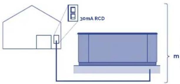
KW
| KW required | |||||||||||
| 2.1 2 | 5 2,8 3 | 2 3 5 | 5 3 | 6.2 7.0 | 7 4.8 6 | ||||||
| Distance | Nominal section of the cable in mm 2 | ||||||||||
| 6 - 11 m 2.5 | 2.5 2.5 | 2.5 4 | 6 10 | 10 10 | 10 | 4 | |||||
| 11 - 15 m | 2.5 | 2.5 | 4 | 4 | 4 | 6 | 6 | 10 | 10 | 10 | 10 |
| 15 - 20 m | 4 4 6 | 6 10 | 10 10 | 16 16 | 6 | ||||||
204
5.6.
natural_image
Illustration of a hand using a tool to adjust or install an electrical component on a metal frame (no text or symbols visible)205
natural_image
Illustration of a blue industrial robot with screw heads and a warning symbol (no text or labels)6a - Single phase
6b & 6c - Three phase
6a. 6b.
flowchart
graph TD
    A["Line 1: ZMW 3: 3x26A"] --> B["OFF"]
    B --> C["Az"]
    B --> D["Ag"]
    E["Line 2: 1 BRN 2 BLU 3 BRN 3 GRN"] --> F["TBs"]
    F --> G["1"]
    F --> H["2"]
    F --> I["3"]
    F --> J["4"]
    K["Ground"] --> L["J60"]
    L --> M["J61"]
    N["Line 3: J60"] --> O["J60"]
    P["Ground"] --> Q["J60"]
    R["Ground"] --> S["J60"]
Three-phase line 380V III BP21G1WL
Remove bridges;
J51-J88 and J52-J62

Changes this bridges
J60-J36 -> TO J60-J45
J41-J12 -> TO J41-J79

Power requirements:
3 Services 5 wires: Line 2, Line2, Line 3, Neutral. Ground 400VCA, 50/60Hz 3 phase, 16A (Circuit breaker rating - 20A max each phase line).
Single line 230V 32A
207
6c.
flowchart
graph TD
    A["230V 3"] --> B["OFF ON"]
    B --> C["A2 ▶"]
    B --> D["A3 ▶"]
    B --> E["A5"]
    F["3 BRN"] --> G["1 BRN"]
    H["1 BRN"] --> I["BLU"]
    J["2 BRN"] --> K["Ground"]
    L["GBN"] --> M["Ground"]
    N["TB1"] --> O["4"]
    N --> P["1"]
    N --> Q["2"]
    N --> R["3"]
    S["1"] --> T["Unfused"]
    U["3"] --> V["Unfused"]
    W["1"] --> X["Unfused"]
    Y["3"] --> Z["Unfused"]
Three-phase line 400V BP013G1 & BP013G2
Remove jumpers:
connecting J51 and J58
connecting J52 and J36

Changes this bridges:
J41 - J53 -> TO J41 - J54
J60-J12 -> TO J60-J45

Put DIP switches A5 on OFF and
A2, A3 on ON position.
Power requirements:
3- Service 5 wires: Line 2, Line
- Line 3. Neutral, Ground
400VCA, 50/60 Hz* 3 phase, 16A
(Circuit breaker rating = 20A max
each phase line). *BP systems
automatically detect 50Hz vs 60Hz
natural_image
Diagram of a container with a curved pipe and dashed liquid, no text or symbols present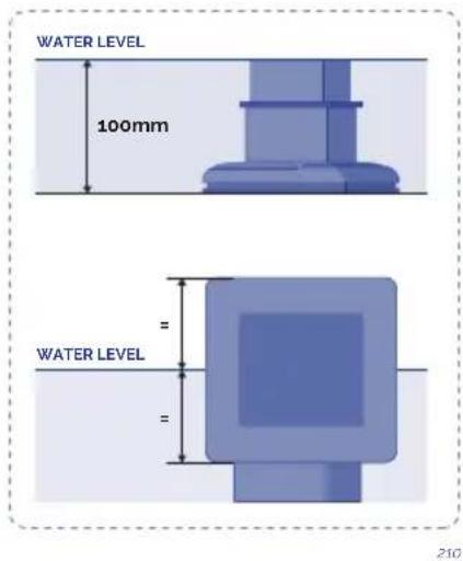
8.9.10.
natural_image
Illustration of a blue electrical fuse component with no visible text or symbols

natural_image
Simple diagram of a rectangular container with a vertical rod and arrow indicating direction, no text or symbols present.

https://www.youtube.com/watch?v=EvKx_CkS_tw
flowchart
graph LR
    A["Cell with internal structures"] --> B["Membrane with arrow"]
    C["Membrane particle"] --> D["Membrane plate with particles"]
    E["Light bulb"] --> F["Light bulb"]
heatmap
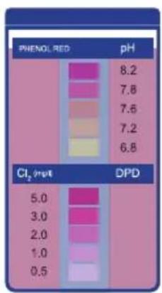
| PHENOL RED | pH | |---|---| | 8.2 | | | 7.8 | | | 7.6 | | | 7.2 | | | 6.8 | | | 5.0 | | | 3.0 | | | 2.0 | | | 1.0 | | | 0.5 | | Cl₂ (m/z) DPD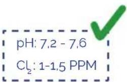
214215
! ATTENTION
This instructions manual contains fundamental information on the safety measures to be adopted when installing, starting-up and operating the spa. It is therefore essential that both the Fitter and the User read these instructions before assembly and start-up.
THE PRODUCT GUARANTEE WILL ONLY BE APPLIED IF IT IS CORRECTLY INSTALLED AND IF THE INSTRUCTIONS IN THE MANUAL HAVE BEEN COMPLIED WITH.
CHECK THE GUARANTEE SHEET AND CAREFULLY READ THE LIMITATIONS CONTAINED WITHIN.
CONTENTS
- INTRODUCTION ...... 13
- GENERAL WARNINGS .... 13
3.1. Warnings 15
3.2. Position and location of the spa....15
3.4.Filling the spa 21
3.5. Electrical connection 22
- START-UP 28
4.1. System start-up ....28
4.2. Water treatment....29
- OPERATING INSTRUCTIONS....31
5.1. Warnings on the use of the spa 31
5.2. Systems 32
5.3. Jets operation....41
5.4. Swimspa controls 42
5.6. Renewing the spa water 42
5.7. Extras 43
- MAINTENANCE 48
6.1. Warnings 48
6.2. Water maintenance ....48
6.3.Filter maintenance 52
6.4. Pre-filter of the pump maintenance 53
6.5. Acrylic maintenance....53
6.6. Light maintenance....54
6.7. Maintenance in periods of non-use or absence 54
- ERROR MESSAGES (TP600 & Touch control panels)....56
- PROBLEMS AND SOLUTIONS....59
- RECYCLING AND THE ENVIRONMENT....60
- EVIDENCE OF CONFORMITY 61
1. INTRODUCTION
This manual contains all the information needed to fully enjoy your SPA. We recommend that you take some time to go over the points detailed below.
If you have any question or doubt on the operation or maintenance of this product, please contact your fitter or local dealer. They are specialists and their professional knowledge will help you to enjoy this product.
IMPORTANT: The manufacturer reserves the right to change the design or specifications without prior notice and without entering into any obligation.
This Spa has been designed and conceived for private use only: any public use shall annul its guarantee.
2. GENERAL WARNINGS
Carefully follow current regulations regarding accident prevention and respect regulations in each country.
- Any modification on the equipment requires prior authorisation from the manufacturer.
Original spare parts and accessories authorised by the manufacturer guarantee greater safety. The manufacturer of the equipment is exempt from all liability for damages caused by using non-authorised spare parts or accessories.
- The manufacturer shall not be responsible for the damages caused by the assembly of non-authorized accessories, nor for those caused by a improper handling by non-qualified personnel. Please contact your authorised dealer or technical assistance service if you have any doubts or need technical assistance.
- The equipment should be installed in a place which has been properly prepared and where all components of the Spa can be easily accessed. The guarantee does not cover work needed to be carried out to install or replace the product. (See the Guarantee).
- The user shall ensure that at qualified adult professionals carry out both the assembly and maintenance works, who have previously carefully read the installation and service instructions.
- Contact the Technical Service of the manufacturer or your local dealer in the event of malfunction or a breakdown.
- The installation of the Spa must at all times meet current regulations applicable in each country, particularly those referring to electrical safety.
- This unit must be installed in an appropriately prepared area with easy access to all the components of the Spa. The Guarantee does not cover any building work required to position or replace the product. (See the Guarantee).
- The floor has to be capable of supporting the expected load.
- During operation, some parts of the equipment are at dangerous electrical voltage levels. Work on each element or equipment can only be performed once it has been disconnected from the mains and with the start-up devices disconnected.
- Safety in the operation of the machine can only be guaranteed if installation and service instructions are followed.
- There is a risk of flooding with this equipment and therefore, the Spa should be installed in an area prepared to collect or drain leaking water (either from below or overflowing water) as a result of using the Spa or from possible leakage in any of its circuits. (See the Guarantee).
- Carefully follow current regulations regarding accident prevention.
- This appliance can be used by children aged from 8 years and above and persons with reduced physical, sensory or mental capabilities or lack of experience and knowledge if they have been given supervision or instruction concerning use of the appliance in a safe way and understand the hazards involved.
• Children shall not play with the appliance. - Cleaning and user maintenance shall not be made by children without supervision.
- The limits indicated on the electrical control panel cannot be exceeded under any circumstances.
- Avoid contact with electrical voltage.
- The appliance should be supplied through a residual current device (RCD) with a rated tripping current not exceeding 30 mA
- In case you use a cover that does not have fastening and/or safety elements for preventing unsupervised access to your spa, it is recommended that you install an alternative element (e.g., access control system, fence, etc.) to prevent the unauthorised access to and use of your spa.
! ATTENTION
Correct earthing connection is essential.
The earth connection circuit of the building must be in perfect condition to guarantee the safety of the Spa user. If you have doubts on the matter, ensure the earth circuit is reviewed by qualified personnel.
The manufacturer shall not be responsible for the damages caused by inadequate maintenance of the ground connection circuit. It is essential that the owner of the Spa tests the Residual Current Device (RCD) at least once a month, to check its good working order.
3. INSTALLATION AND ASSEMBLY
3.1. Warnings
- During the electrical connexion with the equipment have special care in the layout of the cables in the bypass box, make sure no pieces of cables are in the box after closing and that the ground connexion is correctly done.
- Pay special care that no water enters in contact neither with the pumps neither with the electrical parts under tension.
3.2. Position and location of the spa
Before installing and assembling the Spa, ensure that the packaging of the Spa is in perfect condition. Contact your distributor immediately if the packaging is damaged.
Position the Spa horizontally, placing the whole base of the unit on a smooth, flat and level surface, capable of supporting the weight when used (full of water, plus the weight of the bathers).
The Spa cannot be placed on a curved surface or on blocks.
The side where the motors are located should be fully accessible. In order to carry out maintenance tasks, the location of the Spa should enable it to be moved so that all its sides can be easily accessed.
natural_image
Three icons showing a blue container with red X marks, a gray container with red X marks, and a green checkmark (no text or symbols)OUTDOOR INSTALLATION
If an outdoor location is chosen to place the Spa:
Do not expose the Spa to sunlight when it is empty and without a protection cover. Remember that prolonged exposure to sunlight may damage the surface of the Spa and its accessories. Acrylic rapidly absorbs heat from the sunrays reaching very high temperatures which will damage the Spa. Maximum absorption temperature is 60irc C.

natural_image
Two icons: a red X-shaped crossed-out box and a blue container with a green checkmark (no text or symbols)001
It is recommended to place the Spa away from trees, as falling leaves may block the filter.
If the Spa is placed inside glass structures, prevent sunrays shining directly on the Spa through the glass, as the temperature could be excessively hot.
INDOOR INSTALLATION
It is recommended to ensure drainage in the area of the Spa, to prevent water from accumulating around it and to avoid dangerous access areas for bathers.
Remember that the operation of the Spa causes increased damp and therefore, there must be a ventilation system to prevent damp from accumulating which could cause damage in the room where the Spa is located.
The use of a cover reduces heat loss and damp in the room.
! ATTENTION
The spa should not be left empty and uncovered at room temperatures over 20irc C or below 4irc C.
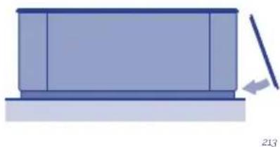
PORTABLE LEVELLING SPAS
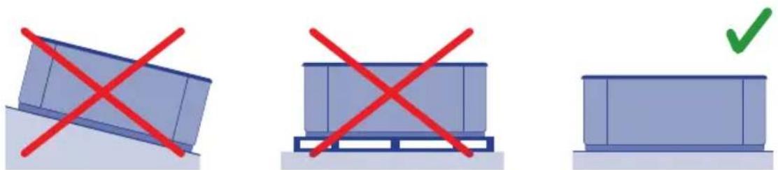
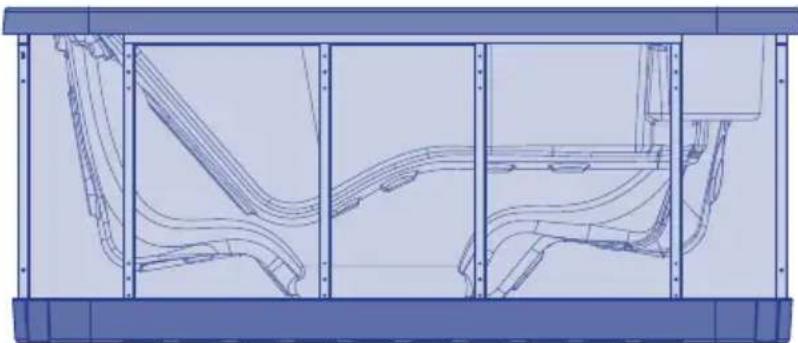
Some spas come with an adjustable metal structure to facilitate their installation. This structure has several points of support. Before filling the spa, these points of support should be adjusted to ensure they are all in contact with the ground.
natural_image
Technical line drawing of a vehicle chassis frame with structural components (no text or symbols)SWIMSPA
TRANSPORT
A1. SWIMSPA - CONTAINER DOWNLOAD
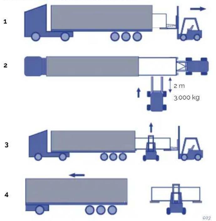
A2. SWIMSPA - CONTAINER DOWNLOAD
1
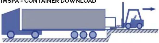
natural_image
Illustration of a blue truck with a forklift and arrow, no text or symbols present2
natural_image
Illustration of a forklift moving a large truck on a flatbed surface (no text or symbols)3

3.000 Ka
2m

004
A3. SWIMSPA - TRUCK DOWNLOAD

005
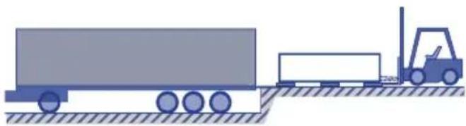
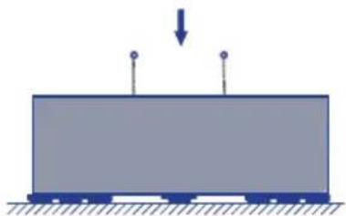
INSTALLATION
B. SWIMSPA - INSTALLATION
Dimensions & Weight: See Technical Doc.
1

2
natural_image
Simple diagram of a rectangular block with two vertical posts and a downward arrow, no text or symbols present.3


4

natural_image
Simple blue rectangular block resting on a surface with hatched ground lines (no text or symbols)
natural_image
3D diagram of a device interior with directional arrows indicating movement or force (no text or symbols)5

natural_image
3D diagram of a blue rectangular device with internal components and a labeled 'OK' (no text or symbols on the device itself)
natural_image
Illustration of a blue industrial container with red prohibition signs and a falling gear (no text or symbols)006
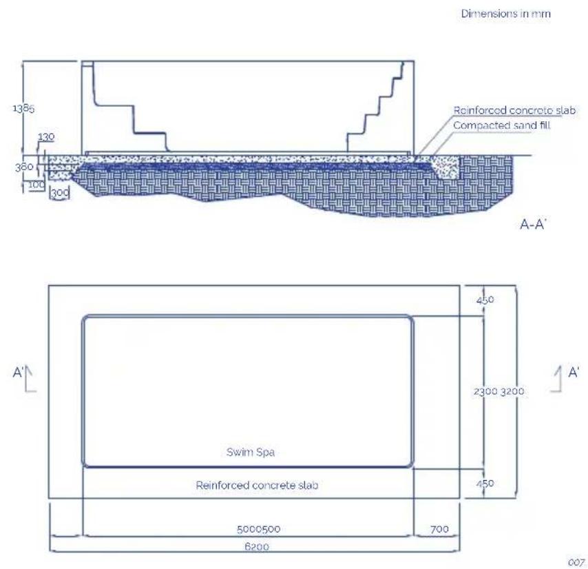
Notes:
This is a picture/illustrative example. It is recommended that an architect or engineer be consulted about the design and building work to ensure that the land is able to withstand the foundation slab when the swimspa is full of water, including the weight of the people who will be using it and the furniture or any other articles that will be in the area around the foundations. Local regulations on foundations and/or building work must also be complied with.
INGROUND VERSION
The Spa structure must be fixed on the floor. Do not hold the Spa by its outer edges.
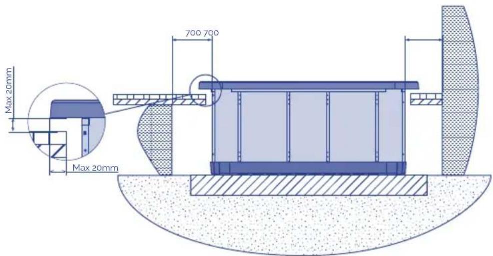
Once settled the Spa, finish the work bearing in mind that the edging of the surface must not be in direct contact with the work (a minimum of 1 cm must be left around the edge).
Bear in mind that you will have to leave enough space to access to the pumps and electrical connections for maintenance. This space should be at least of 0.7 meters.
To seal the tab to the Spa, use a special elastic silicone for aquatic installations.
! ATTENTION
Leave a trapdoor spa access for maintenance. Never cover with concrete. LEAVE 70cm CLEARANCE AROUND THE SPA.
3.3. Drainage
The Spa has a manual emptying system by gravity, through a drainage valve of 3/4".
The drainage valve should always be closed. It should only be open when the Spa is emptied.
If necessary, a drainage system can be installed to connect the Spa to the general drains of the house.
! ATTENTION
Remember that when you drain your spa not all of the water runs off. If your spa is not going to be used for long periods, especially in winter, remove any stagnant water on the seats and on the bottom of the spa with a sponge. Any water remaining in the pipes can be sucked out through the water and air nozzles using a liquid suction pump. The pumps must also be emptied through the drain plug.
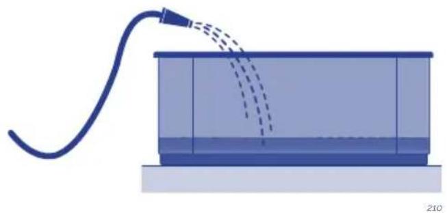
3.4. Filling the spa
PORTABLE SPA
The Spa does not have a specific filling system. It is recommended to use a manual filling system with a garden hose or similar.
Proceed as follows:
- Before starting filling the Spa, locate the drain valve (see 3.3. Drainage) and ensure that it is in the CLOSED position.
- Fill the Spa through the top, with clean water, to the level indicated.
010

natural_image
Pure diagram of a blue square object with dimension lines and no text or symbols011
PORTABLE OVERFLOW SPA
It is recommended to fill the spa manually using a garden hose or a similar system.
Proceed as follows:
Before filling the spa, find the drainage valves and ensure they are all closed, except for the safety outlet, which should always be open.
Fill the spa from above using clean water until the spa starts to overflow.
Fill the three water tanks with the automatic filling.
Connect the water supply to one of the tanks' inlets.
The spa has a filling system that works using a ball cock. The outlet of the ball cock must be connected to the mains supply at a constant water pressure.
When the spa loses water as a result of evaporation, the system automatically fills the tanks.
The compensation tanks have a safety outlet for removing water.

WARNING
The compensation tanks of private overflow spas have a limited capacity. They can hold 280 litres of water, equivalent to 4 partially submerged people. Users should enter the spa one by one and slowly to enable the tanks to absorb the displaced water and prevent water from flowing out of the spa.
! ATTENTION
During the filling process, water should be prevented from entering electrical parts. If seawater is used in the Spa, the circuit components will quickly deteriorate.
Do not fill the Spa with hot water, as this could trigger off the safety thermostat and damage equipment and connections.
Once the Spa has been filled with water, connect the electrical equipment by placing the differential switch in the On position (See Electrical Connection).
Do not use the Spa without first carefully reading all the information detailed in the following points:
- Adjust water ph between 7,2 and 7,6 (see 4.0 section).
- Add all required chemical products recommended in water maintenance (see 6.2 section)
- Select the required temperature (see Installation and assembly of the spa). remember that if the water is cold, it may take 24 hours to reach a temperature of 38irc C .
- Before using the spa, check the ph values once again in case they have changed with the treatments indicated above.
3.5. Electrical connection
! ATTENTION
• This equipment cannot be connected to a normal plug.
- This equipment requires suitable electrical installation. This should be done by a specialised fitter following local electrical safety regulations of each country.
- The electrical input of the Spa should always be protected by a highly sensitive differential. A 30 mA differential is recommended.
• Earthing connection is essential.
- Use a suitable section cable bearing in mind the power of the Spa and distance to the control panel.
• Always follow instructions given in the Safety Warnings chapter of this manual.

WARNING- RISK OF ELECTRIC DISCHARGE
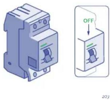
- The electrical supply should be switched off (differential in the OFF position or disconnect the cable from the mains) before carrying out any work.
- Never try to access an electrical component unless you are qualified or are the Head of Maintenance.
• Always use suitable personal protection equipment and tools when handling electrical equipment.
- Never access electrical elements if you are wet, particularly if you have wet feet
- Do not connect the electrical equipment (differential in the ON position), if the Spa is empty of water.
SPA CONNECTION STEPS
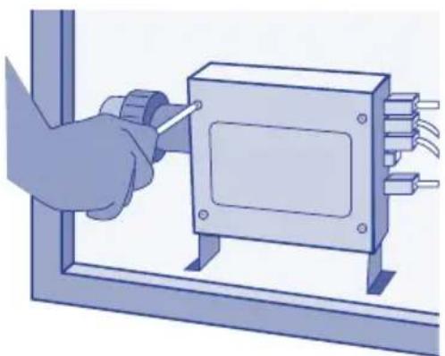
Locate the electrical panel of the Spa.
Locate the electrical control panel; to do this, open the side panel to access the electrical components.
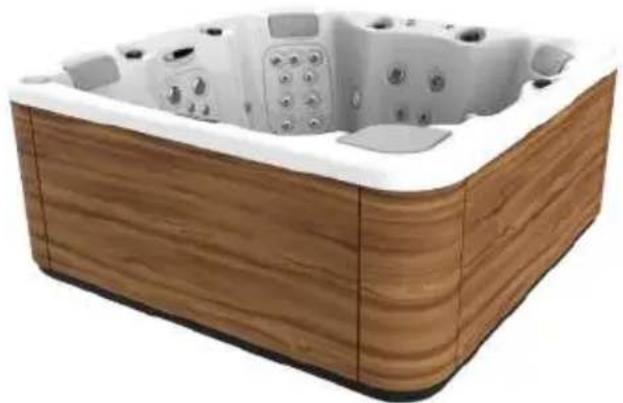
natural_image
Wooden square bathtub with white foam insulation and small digital buttons (no text or symbols visible)012
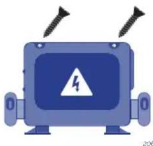
Open the electrical box.
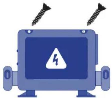
natural_image
Illustration of a blue industrial robot with screw bolts above it and a warning symbol on the screen (no text or labels)013
Connect the spa's electrical control panel to the differential switch.
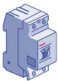
INSTALLATION OF THE DIFFERENTIAL

The electrical installation should incorporate a high-sensitive 2-pole differential in the general mains input panel (the differential is not supplied with the Spa).
014
WARNING
It is essential that the owner of the Spa tests the differential switch at least once a month, to check its good working order.
Check that the differential is in the OFF position. Do not place the differential in the ON position until the Spa is filled with water.
CONNECT THE ELECTRICAL CONTROL PANEL TO THE DIFFERENTIAL
SWITCH
Before carrying out any work on the Spa, make sure it is disconnected from the mains (differential switch in the OFF position, or disconnect the cable from the mains).
Use a suitable cable from the differential switch to the electric cabinet of the Spa, depending on the location and applicable law. The cable section will vary depending on the Spa model and the distance of the installation.
The required kW are indicated in the appendix Technical Specifications of the Spa. The maximum power must be considered, depending on the "High Amp" or "Low Amp" configuration.
DIP Switch Functions
Fixed-Function DIP Switches
A1 Test Mode (normally off).
A2 In "ON" position, add one high-speed pump (or blowe) with Heater.
A3 In "ON" position, add two high-speed pumps (or 1 HS Pump and Blower) with Heater.
A4 In "ON" position, add four high-speed pumps (or 3 HS Pumps and Blower) with Heater.
A5 In "ON" position, enables Special Amperage Rule B. See Special Features section under Configuration Options for functionality with your system. In "OFF" position enables Special Amperage Rule A.
A6 Persistent memory reset (Used when the spa is powering up to restore factory settings as determined by software configuration).
A2, A3 and A4 work in combinatio to determine the number of high-speed devices and blowers that can run before the heat is disabled. f.e. A2 and A3 in the ON position and A4 in the OFF position will allow the heater to operate with up to 3 high-speed pumps (or two HS Pumps and Blower) running at the same time. Heat is disabled when the fourth high-speed pump or blower is turned on.
Note: A2/A3/A4 all ogg = No heat with any high-speed pump or blower.
Assignable DIP Switches
A7 In "ON" position, enables a 5-minutes cool down for some gas heaters (Cooling Time B). In "OFF" position, enables a 1-minute cool down for electric heaters (Cooling Time A).
Undesignted switches are not assigned a function.
The Electric Specification Sheet attached at the end of this manual indicates both the "Low Amp" and the "High Amp" power.
Special Features
Special Features
Default
Feature
No Limitation
Special Amperage Rule
2 high-speed pumps max. Blower turns off with 2 high speed pumps - in Setups 1-4, 6-10, 13, 15, 16, 18
Special Amperage Rule I
No Limitation - in Setups 5, 11, 12, 14, 17
015
CABLE SECTION
To determine the cable section of the electrical installation, see the values indicated in this sheet and the following table:
| KW required | ||||||||||
| 2,1 2 | 5 2,8 3 | 2 3,5 4 | 4 5,3 6 | 2 7,0 7 | 9 8,8 | |||||
| Distance Nominal section of the cable in mm 2 | ||||||||||
| 6 - 11 m 2,52,52,52,544610101010 | ||||||||||
| 11 - 15 m 2,52,54446610101010 | ||||||||||
| 15 - 20 m 4446661010101616 | ||||||||||
For longer distances, increase the cable section accordingly.
Some configurations may require installing 1 32A line, 2 16A lines or even one three-phase line (3 x 16A) to cover the power required by the Spa.
The different configuration options of the electrical control panel are explained further on in this Installation Manual.
Remember that the installation and any changes in the electric configuration must be carried out by qualified personnel, following the current regulations in each country. The manufacturer shall not be responsible for any damage caused by an improper installation or an installation performed by non-qualified personnel.

WARNING
Pay attention to the position of the maximum consumption switch.
The Spa will not operate properly if a cable not corresponding to the distance and power of the Spa is used, and the electrical circuits may overheat which may cause an electrical accident. Always use cable with the suitable section of maximum consumption. In the event of doubt between two values, always use the cable with the greater section.
To connect the supply to the electrical panel of the Spa, locate the packing gland positioned at one end of the electrical panel.
Make sure that there is no electric current in the connection cable (differential switch in the OFF position).
Take the cable to the Spa electrical panel.
Open the cover of the electrical cabinet, insert the feed cable through the free side.
Attention: the indicated blue cable is neutral, and the brown cable indicates the line or phase.
Fasten the terminals as indicated in the following diagrams and the type of electrical supply.
Single line
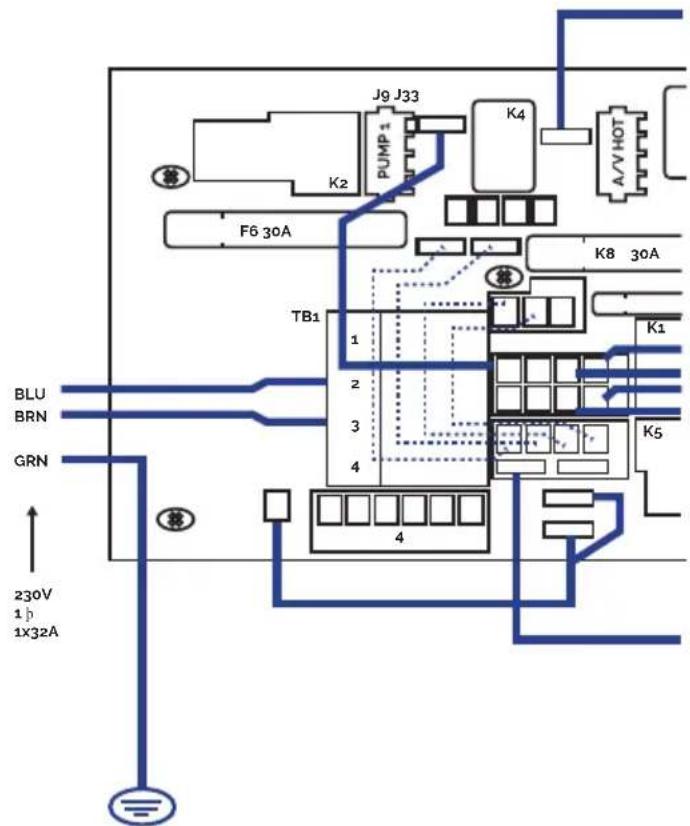
016
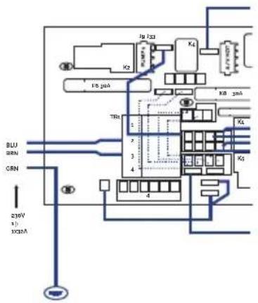
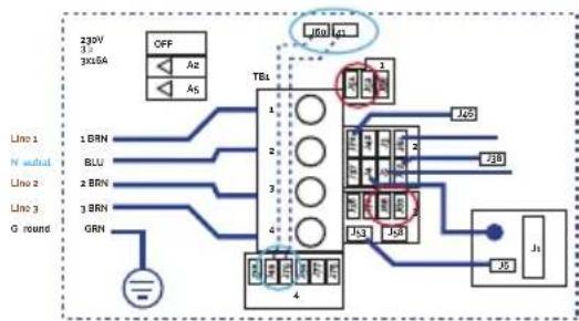
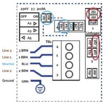
THREE PHASES 400V
flowchart
graph TD
    A["230V 3x16A"] --> B["OFF"]
    B --> C["TBL"]
    C --> D["J50"]
    C --> E["J51"]
    C --> F["J52"]
    C --> G["J53"]
    C --> H["J54"]
    C --> I["J55"]
    C --> J["J56"]
    K["Line 1"] --> L["1 BRN"]
    M["N neutral"] --> N["2 BLU"]
    O["Line 2"] --> P["3 BRN"]
    Q["Line 3"] --> R["3 BRN"]
    S["G round"] --> T["GRN"]
    U["IGBT"] --> V["J50"]
    W["IGBT"] --> X["J51"]
    Y["IGBT"] --> Z["J52"]
    AA["IGBT"] --> AB["J53"]
    AC["IGBT"] --> AD["J54"]
Three-phase line 380V III BP21G1WL
Remove bridges;
J51-J88 and J52-J62
Changes this bridges
J60-J36 -> TO J60-J45
J41-J12 -> TO J41-J79


Power requirements:
3 Services 5 wires: Line 2, Line2, Line 3, Neutral, Ground 400VCA, 50/60Hz 3 phase, 16A (Circuit breaker rating - 20A max each phase line).
208
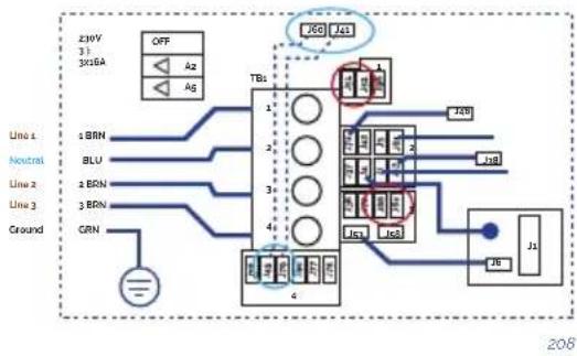
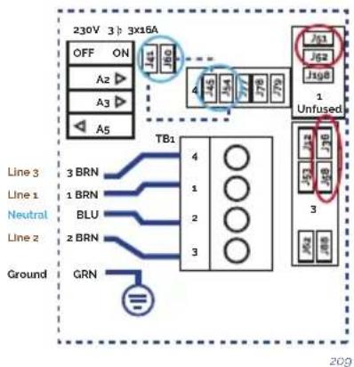
flowchart
graph TD
    A["230V 3p 3x16A"] --> B["OFF ON"]
    B --> C["A2 ▶"]
    B --> D["A3 ▶"]
    B --> E["A5"]
    F["Line 3"] --> G["3 BRN"]
    H["Line 1"] --> I["1 BRN"]
    J["Neutral"] --> K["BLU"]
    L["Line 2"] --> M["2 BRN"]
    N["Ground"] --> O["GRN"]
    P["TB1"] --> Q["4"]
    P --> R["1"]
    P --> S["2"]
    P --> T["3"]
    U["Unfused"] --> V["J61"]
    U --> W["J52"]
    U --> X["J168"]
    U --> Y["1"]
    U --> Z["3"]
    U --> AA["3P"]
    U --> AB["3P"]
    U --> AC["3P"]
Three-phase line 400V BP013G1 & BP013G2
Remove jumpers:
connecting J51 and J58
connecting J52 and J36
Changes this bridges:
J41 - J53 -> TO J41 - J54
J60-J12 -> TO J60-J45
Put DIP switches A5 on OFF and
A2, A3 on ON position.


Power requirements:
3- Service 5 wires: Line 2, Line
- Line 3. Neutral, Ground
400VCA, 50/60 Hz* 3 phase, 16A
(Circuit breaker rating = 20A max
each phase line). *BP systems
automatically detect 50Hz vs 60Hz
209
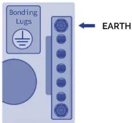
! ATTENTION
Correct earthing is essential
The earthing circuit of the building should always be in perfect condition to guarantee the safety of Spa users. If you have any doubts on this, ensure that the earthing circuit is checked by a duly qualified person. The manufacturer will not be held responsible for possible damage caused by incorrect maintenance of the earthing circuit.
Fasten the earth cable (yellow and green) to the terminal on the outside of the control cabinet as shown in the following diagram:

WARNING
Do not connect the electricity (differential in the ON position) until the Spa is filled with water.
4. START-UP
4.1. System start-up
Check the following configurations before using your spa depending on your spa system:
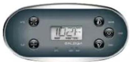
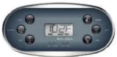
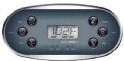
· TP-600
When using a panel with Up and Down buttons (Temperature buttons), pressing Up or Down will cause the temperature to flash. Pressing a temperature button again will adjust the set temperature in the direction indicated on the button. When the LCD stops flashing, the spa will heat to the new set temperature when required.
If a Temperature button is pressed and held when the temperature is flashing, the temperature will continue to change until the button is released.
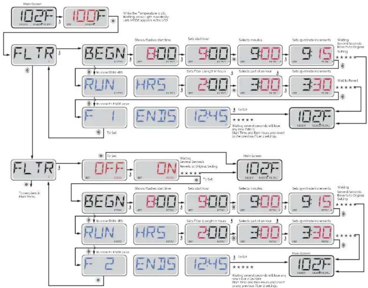
PRE-SET FILTER CYCLES | TP600
flowchart
graph TD
    A["Main Screen"] --> B["102F"]
    B --> C["100F"]
    C --> D["FLTR"]
    D --> E["BEGN"]
    E --> F["8:00"]
    F --> G["9:00"]
    G --> H["9:00"]
    H --> I["9:15"]
    I --> J["To Show RUN IIRS"]
    J --> K["RUN"]
    K --> L["HRS"]
    L --> M["2:00"]
    M --> N["3:00"]
    N --> O["3:30"]
    O --> P["To Set"]
    P --> Q["F 1"]
    Q --> R["ENIS"]
    R --> S["12:45"]
    S --> T["To Set"]
    T --> U["102F"]
    U --> V["REPLACE RANGS FILTERS"]
    V --> W["FLTR"]
    W --> X["OFF"]
    X --> Y["ON"]
    Y --> Z["Main Screen"]
    Z --> AA["BEGN"]
    AA --> AB["8:00"]
    AB --> AC["9:00"]
    AC --> AD["9:00"]
    AD --> AE["9:15"]
    AE --> AF["To Show RUN IIRS"]
    AF --> AG["RUN"]
    AG --> AH["HRS"]
    AH --> AI["2:00"]
    AI --> AJ["3:00"]
    AJ --> AK["3:30"]
    AK --> AL["To Set"]
    AL --> AM["F 2"]
    AM --> AN["ENIS"]
    AN --> AO["12:45"]
    AO --> AP["To Set"]
    AP --> AQ["102F"]
    AQ --> AR["REPLACE RANGS FILTERS"]
    AR --> AS["FLTR"]
· TOUCH PANEL
H = High Temperature Range.
L = Low Temperature Range.
Adjust set temperature higher.
Current water temperature.
Adjust set temperature lower.
PRE-SET FILTER CYCLES | TOUCH PANEL
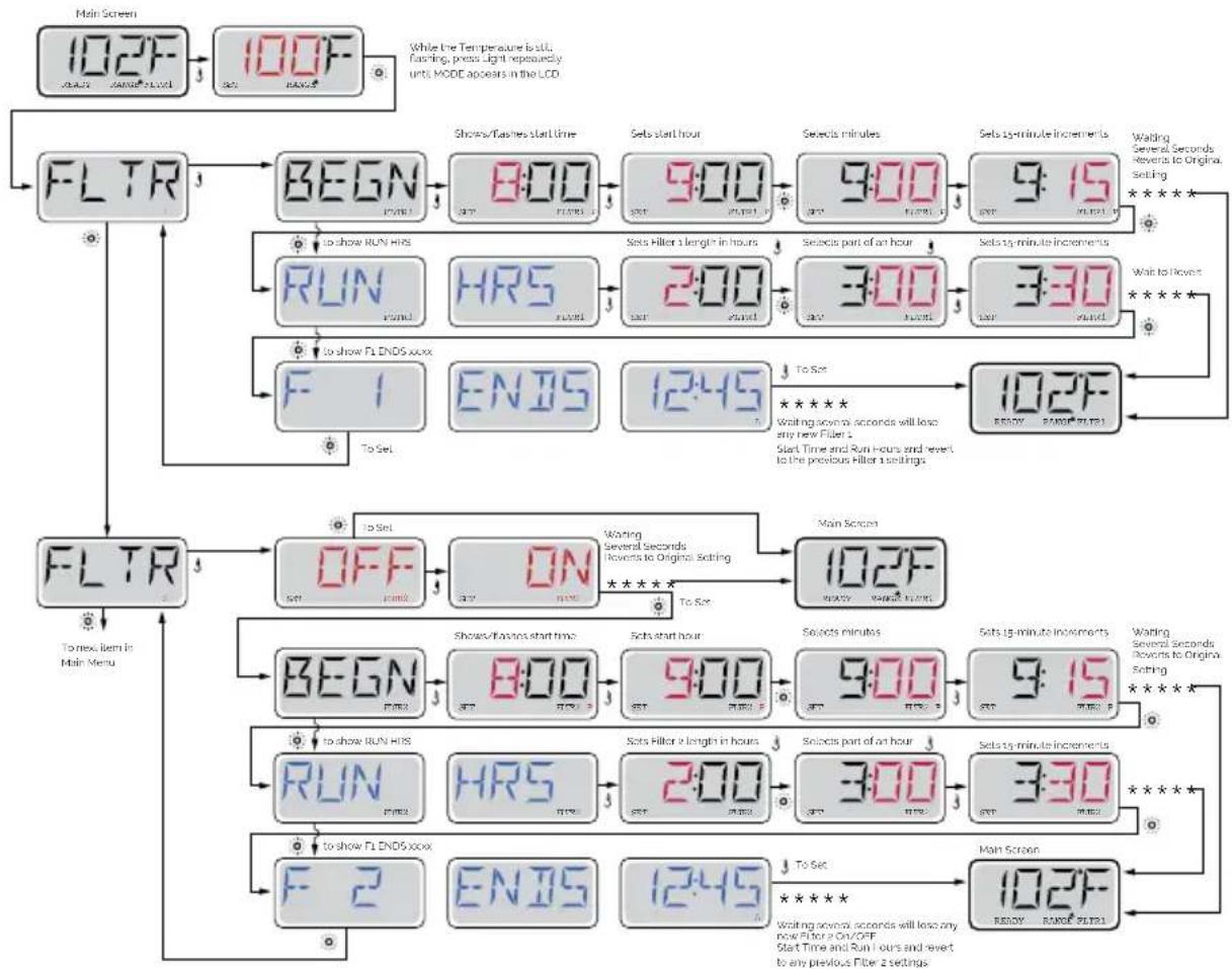
MAIN FILTRATION
Using the same adjustment as Setting the Time, Filter Cycles are set using a start time and a duration. Each setting can be adjusted in 15-minute increments. The panel calculates the end time and displays it automatically.
The Filter Icon the Filter Cycles.

019
on the Settings Screen takes you to a screen where you control
FILTER CYCLE 2 - OPTIONAL FILTRATION
Filter Cycle 2 is OFF by default. Press "1" to view Filter 1. Press "2" once to view Filter 2. Press "2" again to turn Filter 2 ON or OFF. When Filter Cycle 2 is ON, it can be adjusted in the same manner as Filter Cycle 1. It is possible to overlap Filter Cycle 1 and Filter Cycle 2, which will shorten overall filtration by the overlap amount.
4.2. Water treatment
Checking the water status is one of the most important steps.
pH ADJUSTMENT
A pH index of between 7.2 and 7.6 is recommended.
The pH level measures the acidity and alkalinity: Values above 7 are alkali and below 7, are acid.
ATTENTION
It is very important to maintain the correct pH level both for the disinfectant to work properly and to prevent corrosion or deposits on the Spa. Any damage caused by an inadequate pH level is not covered by your Spa guarantee.
• The effects of a very low pH level are:
- The disinfectant will quickly dissipate.
- The equipment of the Spa become rusty.
- The water can start causing skin irritations to bathers.
• The effects of a very high pH level are:
- The disinfectant is less effective.
- Scale may appear on the acrylic and equipment.
- The water may become cloudy.
- The filter cartridge can become blocked.
Check the pH of the Spa water daily using the pH test set. (not supplied)
If the pH is above the indexes, use pH MINOR SPA. Wait for two hours and re-do the pH test.
If the pH is below indexes, use pH MAJOR SPA. Wait for two hours and re-do the pH test.
When the pH index has been adjusted to the values indicated above, proceed to the next step.
DISINFECTION OF THE WATER
Disinfection of the water is of utmost importance in order to destroy algae, bacteria and organisms that could develop in the water. However, excessive disinfection could cause skin and eye irritation.
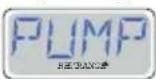
BROMIDE TABLETS are a suitable disinfectant for the Spa water. This product is placed in the pre-filter and gradually dissolves.
Check the residual bromide level daily using the Br analyser set.
The recommended level of residual bromide is between 2.2 and 3.3 ppm.
Do not forget to keep the water in good conditions (see 6.2 Water maintenance)
5. OPERATING INSTRUCTIONS
5.1. Warnings on the use of the spa
Carefully read the following lines regarding accident prevention:
- Do not start-up the Spa unless it is full of water.
- This appliance can be used by children aged from 8 years and above and persons with reduced physical, sensory or mental capabilities or lack of experience and knowledge if they have been given supervision or instruction concerning use of the appliance in a safe way and understand the hazards involved.
• Children shall not play with the appliance. - Cleaning and user maintenance shall not be made by children without supervision.
• Take extreme precautions to stop children from entering the Spa unattended. To avoid accidents, ensure that children are supervised at all times. Never leave children alone in the Spa. Take care when entering and leaving the Spa to avoid slipping on wet surfaces. - Do not allow anybody to play with sharp or metal objects inside the Spa, which could damage the acrylic surface.
- Do not allow any user to access to the electrical parts of the Spa.
- Do not use electronic devices inside the Spa.
- Do not let animals go inside the Spa.
- Do not fill the Spa with other liquid other than fresh, duly treated water.
- Do not fill the Spa with hot water (maximum 35ircC ); let the water heat by itself, otherwise it could damage the temperature probes (see "Temperature Adjustment").
- Do not use the Spa immediately after intense physical exercise.
- Do not use the Spa if you are suffering from a contagious disease or 14 days after recovering from a contagious disease.
- In order to guarantee maximum safety when bathing all our Spas use pumps designed to suction water from anti-vortex, safety drain covers, located on the floor of the Spa. Take special care that these drain covers are not covered by any object or the users (pieces of clothing, hair, legs, etc.). For safety reasons, your head should always be outside the Spa in order to avoid drowning. Do not use the Spa if the drain covers are broken, damaged or unassembled, as apart from damaging the Spa, it could also lead to a risk of drowning.
- The headrests of your Spa are made of synthetic foam, which can be damaged in high concentrations or bromine or chlorine, or low levels of pH. Make sure that when adding chemical products, the headrests are neither totally nor partially immersed in the water. If necessary, remove them until the chemical products have taken effect. Damages resulting from improper use shall not be considered under the guarantee of the product.
-
The Spa includes a cover designed to protect the acrylic surface from sunrays when it is not being used. This cover will also help to keep the water warm, and for sun protection that could damage the acrylic material of the Spa. The cover will require .
-
The appliance should be installed through a residual current device (RCD) with a rated tripping current not exceeding 30 mA
- The cover is designed to protect the spa, not to bear weight. Not even water or snow. Do not place objects on top of the cover. Do not allow people or animals get on the cover. Periodically remove snow to prevent buildup.
- The water should be disinfected thoroughly before using the Spa, especially if it has not been used for a certain period of time, whether or not it has been left with or without water inside. During periods of non-use, traces of stagnant water may remain, which may cause the growth of micro organisms potentially dangerous for health. Therefore, disinfect the Spa as indicated in this manual, ensuring that the pH and disinfectant parameters are suitable.
! ATTENTION
The compensation tanks of private overflow spas have a limited capacity.
They can hold 280 litres of water, equivalent to 4 partially submerged people.
Users should enter the spa one by one and slowly to enable the tanks to absorb the displaced water and prevent water from flowing out of the spa.
RISKS OF HYPERTHERMIA
Prolonged, direct contact with hot water could cause hyperthermia.
This occurs when the internal body temperature reaches levels above the normal temperature of 36.5irc C. It is advised not to bathe for longer than 15 minutes.
Symptoms of hyperthermia are a sudden drop in blood pressure resulting in a sensation of dizziness with the possibility of fainting.
Water temperatures between 37irc C and 40irc C are only considered safe for adults without any health problems. Lower temperatures are recommended for the majority of people and children. The Spa water should never be above 40irc C.

WARNING
Alcohol, drugs or medicines could increase the risk of hyperthermia.
It is not advisable for pregnant women, patients with high blood pressure, a heart condition, diabetes or under medication to use the spa. You should seek doctor's advice.
5.2. Systems
EXISTING SYSTEMS
Your spa is equipped with an electronic control system that will enable you to regulate the temperature of the water, choose the filter cycle that best suits your needs and activate the massage pumps and the blower pump. It will also enable you to turn on your spa lighting, change its colour and sequence. Depending on the design, your spa will have one of the following systems:
· TP600
020
021
022
2 Speed pump
Heater
Spotlight
Circulation Pump
Massage Pumps
Turbo-Blower pump
Heater
Spotlight
Circulation Pump
2 Massage Pumps
Heater
Spotlight
· AUX

023
Fill the spa to its correct operating level. Be sure to open all valves and jets in the plumbing system before filling to allow as much air as possible to escape from the plumbing and the control system during the filling process.
After turning the power on at the main power panel, the top-side panel display will go through specific sequences. These sequences are normal and display a variety of information regarding the configuration of the hot tub control.
PRIMING MODE - M019 | TP600
This mode will last for 4-5 minutes or you can manually exit the priming mode after the pump(s) have primed.
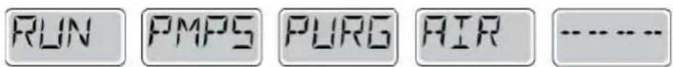
Regardless of whether the priming mode ends automatically or you manually exit the priming mode, the system will automatically return to normal heating and filtering at the end of the priming mode. During the priming mode, the heater is disabled to allow the priming process to be completed without the possibility of energizing the heater under low-flow or no-flow conditions. Nothing comes on automatically, but the pump(s) can be energized by pushing the "Jet" buttons. If the spa has a Circ Pump, it can be activated by pressing the "Light" button during Priming Mode.
You can manually exit Priming Mode by pressing a "Temp" button (Up or Down). Note that if you do not manually exit the priming mode as described above, the priming mode will be automatically terminated after 4-5 minutes. Be sure that the pump(s) have been primed by this time.
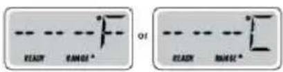
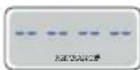
Once the system has exited Priming Mode, the top-side panel will momentarily display the set temperature but the displaywill not show the temperature yet, as shown below. This is because the system requires approximately 1 minute of water flowing through the heater to determine the water temperature and display it.
ADJUSTING THE SET TEMPERATURE | TP600
When using a panel with Up and Down buttons (Temperature buttons), pressing Up or Down will cause the temperature to flash. Pressing a temperature button again will adjust the set temperature in the direction indicated on the button. When the LCD stops flashing, the spa will heat to the new set temperature when required.
If a Temperature button is pressed and held when the temperature is flashing, the temperature will continue to change until the button is released.
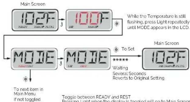
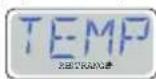
MODE READY & REST / READY IN REST MODE | TP600
In order for the spa to heat, a pump needs to circulate water through the heater. The pump that performs this function is known as the "heater pump." The heater pump can be either a 2-Speed Pump 1 or a circulation pump. READY Mode will circulate water every 1/2 hour, using Pump 1 Low, in order to maintain a constant water temperature, heat as needed, and refresh the temperature display. This is known as "polling."
REST Mode will only allow heating during programmed filter cycles. Since polling does not occur, the temperature display may not show a current temperature until the heater pump has been running for a minute or two.
If the spa is configured for 24HR circulation, the heater pump generally runs continuously. Since the heater pump is always running, the spa will maintain set temperature and heat as needed in Ready Mode, without polling.
In Rest Mode, the spa will only heat to set temperature during programmed filter times, even though the water is being filtered constantly when in Circulation Mode.
flowchart
graph TD
    A["Main Screen"] --> B["102F READY"]
    B --> C["102F MODE"]
    C --> D["Main Screen"]
    D --> E["102F RE-TRANGE FILTER"]
    E --> F["While the Temperature is still flashing, press Light repeatedly until MODE appears in the LCD."]
    G["To next item in Main Menu<br>If not toggled."] --> H["MODE READY TEST"]
    H --> I["MODE MODE"]
    I --> J["To Set ***** Waiting Several Seconds Reverts to Original Setting"]
    K["Toggle between READY and REST<br>Pressing Light when the display is toggled will go to Main Screen"] --> L["End"]
KEY

Indicates Flashing or Changing Segment
Indicates Alternating or Progressive Message every 1/2 second

A temperature button, used for "Action"

Light or dedicated 'Choose' button, depending on control panel configuration

Waiting time that keeps the last change to a menu item.

Waiting time (depends on menu item) that reverts to original setting and ignores any change to that menu item.
Toggle between READY and REST
Pressing Light when the display is toggled will go to Main Screen.
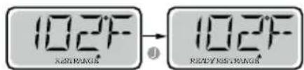
READY Mode will allow the spa to Poll and determine a need for heat. The panel will maintain a "current" temperature display.
Main Screen
REST Mode will not Poll and will only heat during filler cycles. The panel will not display a current temperature at all times.


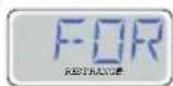
The Main Screen will display RUN PUMP FOR TEMP if the filtration pump has not run for over 1 hour.
The Main Screen will display normally during Filter Cycles or when the spa is in use.
If the filtration pump has been off for an hour or more, when any function button, EXCEPT Light, is pressed on the panel, the pump used in conjunction with the heater will run so that temperature can be sensed and displayed.
READY-IN-REST MODE | TP600
READY/REST appears in the display if the spa is in Rest Mode and Jet 1 is pressed. It is assumed that the spa is being used and will heat to set temperature. While Pump 1 High can be turned on and off, Pump 1 Low will run until set temperature is reached, or 1 hour has passed. After 1 hour, the System will revert to Rest Mode. This mode can also be reset by entering the Mode Menu and changing the Mode.
Main Screen Main Screen
PRE-SET FILTER CYCLES | TP600
flowchart
graph TD
    A["Main Screen"] --> B["102F"]
    B --> C["100F"]
    C --> D["FLTR"]
    D --> E["BEGN"]
    E --> F["8:00"]
    F --> G["9:00"]
    G --> H["9:00"]
    H --> I["9:15"]
    I --> J["Walding Several Seconds Revers to Original Setting"]
    E --> K["To show RUN HRS"]
    K --> L["HR5"]
    L --> M["2:00"]
    M --> N["3:00"]
    N --> O["3:30"]
    O --> P["To Show"]
    P --> Q["To set"]
    Q --> R["102F READY PANELS"]
    R --> S["F 1"]
    S --> T["ENJS"]
    T --> U["12:45"]
    U --> V["102F READY PANELS"]
    V --> W["To Next Item in Main Menu"]

    X["Main Screen"] --> Y["BEGN"]
    Y --> Z["8:00"]
    Z --> AA["9:00"]
    AA --> AB["9:00"]
    AB --> AC["9:15"]
    AC --> AD["Walding Several Seconds Revers to Original Setting"]
    Y --> AE["To show RUN HRS"]
    AE --> AF["HR5"]
    AF --> AG["2:00"]
    AG --> AH["3:00"]
    AH --> AI["3:30"]
    AI --> AJ["To Show"]
    AJ --> AK["To set"]
    AK --> AL["102F READY PANELS"]
    AL --> AM["To Next Item in Main Menu"]

    style A fill:#f9f,stroke:#333
    style B fill:#f9f,stroke:#333
    style C fill:#f9f,stroke:#333
    style D fill:#ccf,stroke:#333
    style E fill:#cfc,stroke:#333
    style F fill:#cfc,stroke:#333
    style G fill:#cfc,stroke:#333
    style H fill:#cfc,stroke:#333
    style I fill:#cfc,stroke:#333
    style J fill:#cfc,stroke:#333
    style K fill:#cfc,stroke:#333
    style L fill:#cfc,stroke:#333
    style M fill:#cfc,stroke:#333
    style N fill:#cfc,stroke:#333
    style O fill:#cfc,stroke:#333
    style P fill:#cfc,stroke:#333
    style Q fill:#cfc,stroke:#333
    style R fill:#cfc,stroke:#333
    style S fill:#cfc,stroke:#333
    style T fill:#cfc,stroke:#333
    style U fill:#cfc,stroke:#333
    style V fill:#cfc,stroke:#333
    style W fill:#cfc,stroke:#333
    style X fill:#cfc,stroke:#333
PURGE CYCLES | TP600
In order to maintain sanitary conditions, as well as protect against freezing, secondary water devices will purge water from their respective plumbing by running briefly at the beginning of each filter cycle. (Some systems will run a certain number of purge cycles per day, independent of the number of filter cycles per day. In this case, the purge cycles may not coincide with the start of the filter cycle.)
If the Filter Cycle 1 duration is set for 24 hours, enabling Filter Cycle 2 will initiate a purge when Filter Cycle 2 is programmed to begin.
MEANING OF FILTER CYCLES | TP600
- The heating pump always runs during the filter cycle*
- In Rest Mode, heating only occurs during the filter cycle
- Purges happen at the start of each filter cycle
* For example, if your spa is set up for 24/hour circulation except for shutting off when the water temperature is 3ircF / 1.3ircC above the set temperature, that shutoff does not occur during filter cycles.
CONTROL SYSTEM FOR Touch panel
Fill the spa to its correct operating level. Be sure to open all valves and jets in the plumbing system before filling to allow as much air as possible to escape from the plumbing and the control system during the filling process.
After turning the power on at the main power panel, the top-side panel will display a splash screen or startup screen.
- H = High Temperature Range. L = Low Temperature Range.
- R = Ready Mode. RR = Ready And Rest Mode. IR = Rest Mode.
- F1= Filter1 Mode. F2 = Filter2 Mode. F+ = Filter 1 and 2 Mode.
- O3=Water Care (Ozone or UV, depending the system installed) is Running.
If you don't see the icon that means the Disinfection (Ozone or UV) is OFF
- C= Cleanup Cycle is Running.
Note: Not all systems that can run a Cleanup Cycle display this icon.
- Wi-Fi icon just indicates that the Wi-Fi link is connected. It does not indicate signal strength.
Note: Not all systems that support Wi-Fi display this icon.
- Lock Icon: When displayed, indicates the panel is in a locked mode. To unlock or lock a setting or panel lock, first press the corresponding icon on the Lock Screen then press the word "Lock" for 5+ seconds until the text and icon change to the opposite state.
There are 2 lock icons that can be shown on the title bar of most screens.
A tall skinny one is representing a settings lock is applied. It is shown on screens that are affected by the settings lock. And the standard lock icon which represents the Panel being locked. If both settings and panel are locked, only the panel lock
will show since the settings lock doesn't do much in that situation. When the panel is locked, the Settings Screen will only show items not affected by that lock (System Info and Lock Screens).
-
= Invert (or flip) Screen.
-
= Light is turned ON. = Light is Inactive. = Light is Disabled.
-
= Music is Active. = Music is Inactive. = Music is Disabled.
-
Message Waiting Indicator:
The Message Waiting Indicator will show one of the following icons:
= Fatal error (Spa can't function until it's fixed)
= Normal Error or Warning
= Reminder Message
i = Information Message.
Some messages will include the "Call for Service" text as it requires a service technician to fix the problem. If the panel is locked and a message alert appears, you will be taken to the UNLOCK screen before you can clear the message. Touching the Error/Warning/Reminder/Info Icon on the Message Screen will take you to the System Information Screen to allow for troubleshooting over the phone or for a field service tech to better understand what is going on. Exiting the System information Screen will take you back to the Message Screen in that situation.
-
Adjust set temperature higher.
-
= Spa Equipment Control Icon. Brings up a screen where the spa jets, blower or other equipment can be controlled. = Jet is Inactive. Indicates if a pump is running or not.
-
Indicates if the temperature is in °F = Fahrenheit or °C = Celsius.
-
Current water temperature.
-
Setting Icon. 🔒 = Settings is Active. 🔔 = Settings is Inactive (when a Lock is applied). Takes you to Settings Screen.
Where the available specific features that can be adjusted for the control can be adjusted. The same goes for the Utilities Screen and the Test Screen (used by Spa Technicians).
-
Indicates when the spa heater is on.
-
Adjust set temperature lower.
Note: After 30 minutes* the display will automatically go into sleep mode, which turns the display off. This is normal operation. Touch anywhere on the screen to wake the panel up.
The Settings Screen is where all programming and other spa behaviors are controlled. Each icon on the Settings screen takes you to a different screen, where one or more setting may be viewed and/or edited.
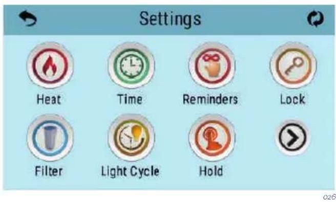
The Heat Icon takes you to a screen where you control the Heat Mode and the Temperature Range.
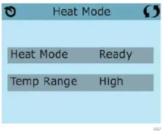
DUAL TEMPERATURE RANGES (High vs Low) | TOUCH PANEL
This system incorporates two temperature range settings with independent set temperatures. The specific range can be selected on the Settings screen and is visible on the Main Screen in the upper left corner of the display. These ranges can be used for various reasons, with a common use being a “ready to use” setting vs. a “vacation” setting.
Each range maintains its own set temperature as programmed by the user. This way, when a range is chosen, the spa will heat to the set temperature associated with that range.
High Range can be set between 80irc F and 104irc F/27°C and 40irc C. Low Range can be set between 50irc F and 99irc F/10°C and 37irc C.
Freeze Protection is active in either range.
HEAT MODE - READY vs REST | TOUCH PANEL
In order for the spa to heat, a pump needs to circulate water through the heater. The pump that performs this function is known as the "heater pump".
The heater pump can be either a 2-speed pump (Pump 1) or a circulation pump.
Rest Mode will only allow heating during programmed filter cycles. Since polling does not occur, the temperature display may not show a current temperature until the heater pump has been running for a minute or two.
CIRCULATION MODE | TOUCH PANEL
If the spa is configured for 24HR circulation, the heater pump generally runs continuously. Since the heater pump is always running, the spa will maintain set temperature and heat as needed in Ready Mode, without polling.
In Rest Mode, the spa will only heat to set temperature during programmed filter times, even though the water is being filtered constantly when in 24HR circulation mode.
READY-IN-REST MODE | TOUCH PANEL
Ready in Rest Mode appears in the display if the spa is in Rest Mode and the Jets 1 Button is pressed. The spa is supposed to be in use and it will be heated up to the selected temperature. Meanwhile Pump 1 High can be on or off, the Pump 1 Low will be working until the temperature selected is reached or when one hour has passed by. After that, the System will revert to Rest Mode. This mode can also be reset by selecting the Heat Mode line on the Screen shown here.
Using the same adjustment as Setting the Time, Filter Cycles are set using a start time and a duration. Each setting can be adjusted in 15-minute increments. The panel calculates the end time and displays it automatically.
The Filter Icon 📋 on the Settings Screen takes you to a screen where you control the Filter Cycles.
FILTER CYCLE 2 - OPTIONAL FILTRATION
Filter Cycle 2 is OFF by default. Press "1" to view Filter 1. Press "2" once to view Filter 2. Press "2" again to turn Filter 2 ON or OFF. When Filter Cycle 2 is ON, it can be adjusted in the same manner as Filter Cycle 1. It is possible to overlap Filter Cycle 1 and Filter Cycle 2, which will shorten overall filtration by the overlap amount.
PURGE CYCLES
In order to maintain sanitary conditions, as well as protect against freezing, secondary water devices will purge water from their respective plumbing by running briefly at the beginning of each filter cycle. (Some systems will run a certain number of purge cycles per day, independent of the number of filter cycles per day. In this case, the purge cycles may not coincide with the start of the filter cycle.)
If the Filter Cycle 1 duration is set for 24 hours, enabling Filter Cycle 2 will initiate a purge when Filter Cycle 2 is programmed to begin.
MEANING OF THE FILTER CYCLES
- The heating pump always runs during the filter cycle*.
- In Rest Mode, heating only occurs during the filter cycle.
- Purges happen at the start of each filter cycle.
* For example, if your spa is set up for 24/hour circulation except for shutting off when the water temperature is 3ircF / 1.3ircC above the set temperature, that shutoff does not occur during filter cycles.
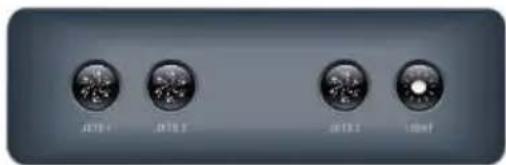
5.3. Jets operation
The water jets provide a hydrotherapy pressure jet. It is a closed circuit, where the water is absorbed by 1 or 2 pumps (depending on the SPA model) through the drain and driven to the jets.
The hydromassage effect is provided by the jet, when the circuit water mixes with the outside air, in the so-called Venturi effect.
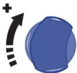
To adjust the amount of air driven into the jets, simply turn the air input tab (venturis) as follows.
natural_image
Blue 3D sphere with a plus sign and curved arrow, no text or symbols present028
Each air inlet activates a certain group of jets.
Some jets can also adjust the flow intensity on opening and closing the water flow. To do this, proceed as follows:

natural_image
Blue circular object with concentric rings and a black curved arrow pointing downward, no text or symbols present.029
! ATTENTION
Do not attempt to turn the outer ring of the jet, forcing it because you could damage it.
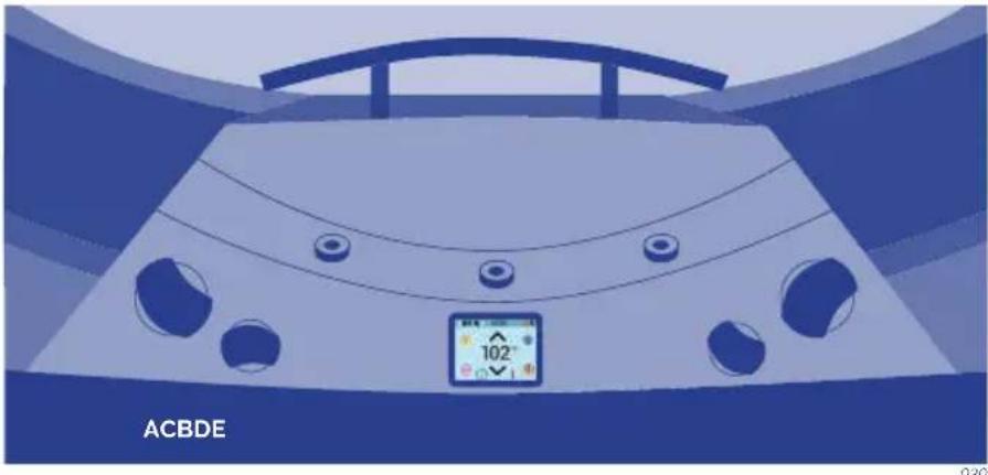
5.4. Swimspa controls
natural_image
Top-down view of a car with visible steering wheel, dashboard, and control panel (no text or symbols on the diagram itself)A - JETSTREAM CONTROL
With the jetstream control you can choose the power of the bottom jetstream and the massage.
B - FOUNTAINS CONTROL
Turning the fountains control you can regulate the flow of the three fountain jets. The fountain only runs when the filtration circuit is running or the spa is in heating process.
C - MAIN CONTROL PANEL
With the electronic main control panel you can turn on or turn off the Jets, Blower (optional) and Light, set the Temperature, the filtration cycles and Time.
D - AIR CONTROL
With the air input valve you can adjust the air turbulence of the jetstream.
E - JETSTREAM CONTROL
With the jetstream control you can choose the power of the top jetstream and the massage.
5.6. Renewing the spa water
To change the Spa water:
- Disconnect the electrical equipment, placing the differential switch (installed in the main input of the home) in the OFF position.
- Locate the drain valve (see 3.3 Drainage) and turn the valve to the OPEN position. The Spa will empty by gravity through the general drain.
- Once the Spa is empty, inspect the acrylic and clean if necessary (see point 6.5 Acrylic Maintenance). Turn the drain valve to the CLOSED position.
• Fill the Spa with clean water (see 3.4 Filling the spa)
5.7. Extras
AROMATHERAPY
The AROMATHERAPY system gives customers a whole host of new sensations by introducing any aroma chosen through the air massage circuit.
The AROMATHERAPY system does not generate any waste products in the water, as happens with conventional oils, which dirty the water and can cause unpleasant effects, as well as blocking up the filter.
The way it works is straightforward and it is easy to maintain. Just place one of the AROMATHERAPY refills into the dispenser on the spa's outer surface and, when the lid is closed, switch the air circuit on.
This system does not work with any kind of refill (no liquids can be added). Only those that appear in catalogue may be used.
Note: Do not leave the lid of the aroma dispenser off. water or another liquid could get into it and damage the air pump.
AUDIO
To clean your music system and loudspeakers, avoid using water at high pressure, such as a hose fitted with a high-pressure nozzle.
Depending on your spa's features your spa can be equipped with Bluetooth Sound System or Bluetooth Surround Sound:
BLUETOOTH SOUND SYSTEM
The system is made up of a subwoofer and two strategically placed loudspeakers in the cabinet. You will be able to connect your mobile devices to the spa with this system.
Sync the Bluetooth device
-
Turn the Bluetooth device on.
-
Select AV ACUÁTICO from the list of available devices for pairing (no password is required).
The system is equipped with a subwoofer and four loudspeakers. It uses the Bluetooth function to connect the sound system to your tablet or smartphone. In addition, you will be able to listen to your favourite AM/FM radio stations, and connect an auxiliary input cable or USB flash drive. The LED screen will tell you what is playing.
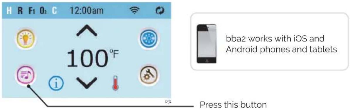
HOME SCREEN
BLUETOOTH CONNECTION
- Power up the system pack with bba2 already connected to the system pack
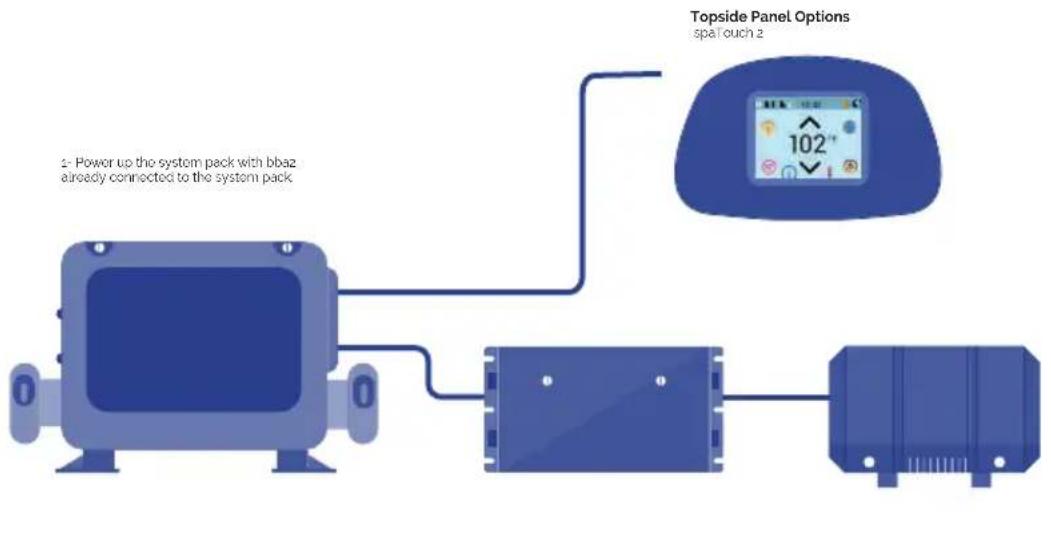
flowchart
graph TD
    A["Device 0"] --> B["Switch"]
    B --> C["Device 1"]
    C --> D["Topside Panel Options: spa touch 2"]
    note1["2- Power up the system pack with bbaz already connected to the system pack"]
    note1 --> note2["102°"]
- On the topside panel press the music button. Next, press the power button

3 - Turn on Bluetooth function of your smart device or music device
4 - On your smart device or music device, click search for Bluetooth device. Make sure you are close enough to the spa tub.
5 - Select "PPME70BT" from the pairing list.
6 - Click "Connect." Once connected, you can now play your favorite music from your smart device or music device.
bba2 operates up to 100 feet in open air. Ranges vary as they are dependant on installations.
BLUETOOTH SCREEN
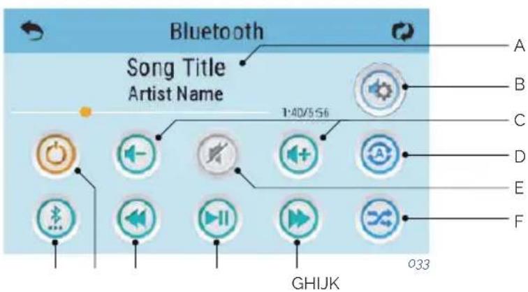
A - Song, Artist Song,
Lenght, Elapsed Time
B - Settings
C - Volume + / -
D - Repeat
- Repeat one song
- Repeat all songs
E - Mute On/Off
F - Shuffle
G - Track forward
H - Play/Pause
I - Track Back
J - Power On/Off
K - Input Modes:
Bluetooth, USB, Line in
Some icons such as "Repeat" may not appear if music isn't playing
ADJUST SETTINGS

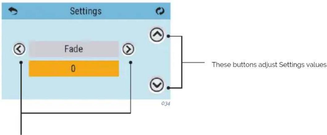
These buttons navigate to the
following Settings:
· Balance
· Bass Gain
· EQ Preset
·Fade
· Filter
FITNESS KIT
There are two types of audio filters: Low Pass, High Pass.
These filters apply to the rear speaker output only. Select
the Low Pass for subwoofers or High Pass for tweeters. Or,
select OFF if filtering is not desired. Normal speakers do
not require filtering.
BENEFITS
Swimming with the FITNESS KIT helps build strength and burn calories, giving you the same benefit as lap swimming. In just minutes a day, you can be on your way to having a dynamic cardiovascular workout, a fit body with firm, toned muscles.
PROPER USE
To clarify the proper use of the FITNESS KIT is necessary to follow some methods that will “guarantee” that your product will be used properly and will eliminate any possibility of breakage or rod failure. These units are specifically engineered to provide “resistance technique and aerobic exercise in water”, not a land/dry based swim system.
Notes:
- Do not "OVER STRETCH" cord more than 50% of its original length!
- Do not jump off side of spa/pool with belt/tether attached.
- Do not push off side the spa/pool, start swimming once you are in pool and sack is out of latex cord.
SWIMMING RECOMMENDATIONS:
-
You can swim "slowly to moderate" and accomplish maximum aerobic strength and conditioning without swimming hard.
-
Do not try to reach the other side of your spa/pool, failure may occur.
These units are made for resistance, "LET THE WATER DO THE WORK".
- When swimming any one of 4 strokes, fins a rhythm in your stroke where you fluctuate forward and backwards; but basically stay in a defined swim space.
CARE INSTRUCTIONS
- Rinse FITNESS KIT with fresh water after every use.
- STORE IN A COOL, DRY PLACE WHEN NOT IN USE to avoid excessive damage from the elements. Prolonged exposure to UV rays may have adverse effects on some of the components. It's best to store all components in the provided bag.
- Inspect your FITNESS KIT before each use. DO NOT USE if there are any visible signs of damage or excessive wear and tear. DON'T RISK IT.
ACCESSORIES
Arm Exercise Handles
Leg Exercise Straps
Exercise Bundles
ROW-EXERCISE
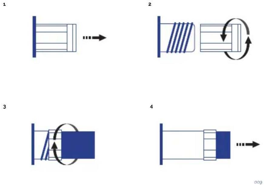
To shorten cords on tether cord and row-exercise kits follow these instructions:
- Cord is attached with four (4) components, hook, ball, collar & cord/tubing.
- To shorten cord/tubing twist off the HOOK portion of the connections by turning counter-clockwise.
- Hold collar with hand or pliers and push/squeeze cord/tubing outwards away from collar.
- Remove the ball by squeezing outwards towards end of card/tubing.
- Cut off length of cord/tubing desired and reinsert ball 1.3cm back into cord/tubing and pull back into collar.
- Reconnect hooks by turning clockwise until tight. Function is complete!
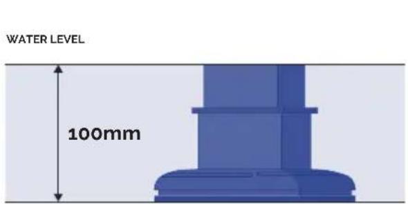
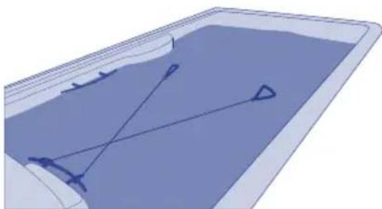
RECOMMENDED FITNESS KIT CORD FIXATION
Fix the cord on the spa/pool as detailed below.
natural_image
3D diagram of a container with internal geometric lines and arrows, no text or symbols present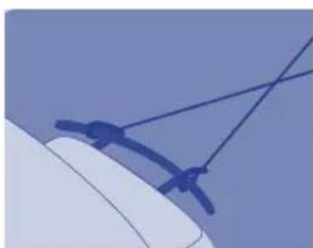
natural_image
Close-up of a computer mouse with a blue cable strap (no text or symbols visible)035
6. MAINTENANCE
The Spas are built with maximum quality and with the hardest wearing materials available. Proper care and maintenance will ensure a long life-span of the Spa and its components.
6.1. Warnings
- Before carrying out any electrical or mechanical maintenance work, make sure that the machine is disconnected from the mains, and that the start-up devices are blocked.
- Do not handle the equipment with wet feet.
- Before carrying out any work on the Spa, it should be switched off from the electrical supply (differential in the OFF position, or disconnect the mains cable).
- Remember that this equipment can not be connected to a normal plug.
- This equipment requires suitable electrical installation. This should be performed by a qualified person following the electrical safety standards of each country.
- The electrical supply of the Spa should always be protected by a highly sensitive differential. A 30 mA differential is recommended.
- Earth connection is essential. The earthing circuit of the building should always be in perfect condition to guarantee the safety of the Spa user. If you have any doubts on this, ensure that the earth circuit is checked by a qualified person. The manufacturer is not responsible for possible damage caused by unsuitable maintenance of the earth circuit.
- Do not connect the electrical equipment (differential in the ON position), if the Spa is empty of water.
- Use a cable of a section suitable to the power of the Spa and the distance to the panel.
• Always observe the instructions included in Safety Warnings chapter of this manual. - Never try to access an electrical component unless you are qualified or are the Head of Maintenance.
- Never handle electrical elements with wet feet.
- Means must be incorporated to disconnect the spa from the electrical network as part of the fixed installation, according to the current regulations.
6.2. Water maintenance
The user must pay particular attention to the maintenance of water. Maintenance will depend on the mineral content of the water used, how often the Spa is used and how many people use the Spa.
ANTI-FREEZE PROTECTION
If the temperature sensors detect a drop in temperature to below 6.7irc C, the heating element and filter pump will connect automatically to prevent the water from freezing and the damage this could cause the Spa.
The equipment will remain connected for 4 minutes after the temperature reaches 7.2irc C.
In colder climates, an additional temperature sensor can be added as a precaution and to
avoid freezing conditions not detected by the standard sensor.
If the pump turns off in this situation, empty the Spa and contact your authorised dealer or Technical Assistance Service.
SAFETY IN THE USE OF CHEMICAL PRODUCTS
Before using a chemical product, read the instructions on the product label carefully.
- It is advisable that always the same person handles the chemical products. Keep these products away from children.
- Add the exact amounts to the water, as specified.
- Keep containers tightly closed in dry, well-ventilated places.
- Do not inhale chemical products, and take care not to let them come into contact with the eyes, nose or mouth. Wash hands after use.
- Follow the emergency instructions on the product label in the event of an accident or ingestion.
- Do not smoke while handling these products – they may be flammable.
- Do not store these products inside the Spa unit.
- Do not mix products. Add first one and then the other to the water, to avoid possible reactions.
- Do not add chemical products to the water if there is someone in the Spa.
MAINTENANCE SCHEDULE OF THE SPA WATER
All chemical products: Bromine in tablet form, Algaecides, Anti-calcareous and pH reducer, must be added to a floating dispenser (not supplied), with the massage pump on for at least ten minutes.
pH ADJUSTMENT
A pH index of between 7.2 and 7.6 is recommended.
The pH level measures the acidity and alkalinity: Values above 7 are alkali and below 7, are acid.
! ATTENTION
It is very important to maintain the correct pH level both for the disinfectant to work properly and to prevent corrosion or deposits on the Spa. Any damage caused by an inadequate pH level is not covered by your Spa guarantee.
• The effects of a very low pH level are:
- The disinfectant will quickly dissipate.
- The equipment of the Spa become rusty.
- The water can start causing skin irritations to bathers.
• The effects of a very high pH level are:
- The disinfectant is less effective.
- Scale may appear on the acrylic and equipment.
- The water may become cloudy.
- The filter cartridge can become blocked.
Check the pH of the Spa water daily using the pH test set. (not supplied)
If the pH is above the indexes, use pH MINOR SPA. Wait for two hours and re-do the pH test.
If the pH is below indexes, use pH MAJOR SPA. Wait for two hours and re-do the pH test.
When the pH index has been adjusted to the values indicated above, proceed to the next step.
DISINFECTION OF THE WATER
Disinfection of the water is of utmost importance in order to destroy algae, bacteria and organisms that could develop in the water. However, excessive disinfection could cause skin and eye irritation.
BROMIDE TABLETS are a suitable disinfectant for the Spa water. This product is placed in the pre-filter and gradually dissolves.
Check the residual bromide level daily using the Br analyser set.
The recommended level of residual bromide is between 2.2 and 3.3 ppm.
USE OF SPECIAL PRODUCTS
Apart from products to maintain the pH and disinfectant level, there are other products formulated especially for use in Spas that will help you to maintain the water and installation in perfect condition.
- PA-ANTI-CALCAREOUS: This prevents the precipitation of calcium salts (scale), particularly in hard water. This product should be added weekly and whenever the water is renewed.
- SPA-ALGAECIDE: This algaecide prevents algae from growing in the Spa water. This product is added weekly and whenever the water is renewed.
- SPA-ANTIFOAM: Foam is often formed owing to the agitation of the water and grease present in the water. Whenever there is a significant amount of foam, remove it with Spa-Antifoam.
- SPA-DEGREASER: To remove rings of dirt and grease that form on the walls of the Spa. To use this product, it is recommended to empty the Spa and apply a degreaser with a sponge on the parts to be cleaned. Rinse immediately with plenty of water.
OZONE GENERATOR
Ozone, O3, is an oxidising chemical component which is very effective in disinfecting water. Its main advantage is that it leaves no chemical residue and is odourless.
Its disinfectant properties are based on its oxidising potential, which leads to the elimination of any organic matter that there may be in the water.
In order to produce ozone, some Spas have an ozonator which, with electricity, can produce ions of ozone from atmospheric oxygen. This process occurs automatically, and the product generated is injected via the filtration return nozzles. Thus, it is not necessary for the user to activate any mechanism for its generation.
The water is collected by the overflow, the drains or the skimmer, due to the suction of the filter pump.
Then it passes through the heat exchanger and in its outlet it is injected with ozone. The water is distributed via the filtration return system.
Ozone treatment does not exclude the use of other chemical products such as Bromine or Chlorine.
The ozone is considered as a complementary process to the ones above, thus reducing the consumption of Bromine or Chlorine.
QUICK GUIDE TO THE APPLICATION OF CHEMICAL PRODUCTS
| Reason for Use Amounts per m | 3 of water Frequency of use | ||
| pH Minor Spa | Add if the pH level is above acceptable levels (7.2-7.6 ppm). | Add following recommendations of the chemical product manufacturer. | Analyse the pH daily with the pH Test. |
| pH Major Spa | Add if the pH level is below acceptable levels (7.2-7.6 ppm). | Add following recommendations of the chemical product manufacturer. | Analyse the pH daily with the pH Test. |
| Bromide tablets | Add if the Br level is below acceptable values (2.2-3.3 ppm). | Add following recommendations of the chemical product manufacturer. | Analyse the Br daily with the Br Test. |
| Anticalcareous | To prevent precipitation of calcium salts (scale). | Add following recommendations of the chemical product manufacturer. | Once a week and whenever the water is renewed. |
| Spa Algaecide | Prevents algae from growing in the water. | Add following recommendations of the chemical products manufacturer. | Once a week and whenever the water is renewed. |
| Degreaser | To eliminate rings of dirt on the walls of the Spa. | Rub with a sponge and immediately rinse with abundant water. | Whenever dirt is observed on the walls of the Spa. |
| Antifoam | Foam in the water. Add following | recommendations of the chemical product manufacturer. | Whenever foam appears in the water. |
6.3. Filter maintenance
! ATTENTION
It is advisable to periodically check the condition of the filter cartridge. If dirt is observed, it must be clean or replace it. Remember that a clogged filter produces a drop in the flow of water, can cause a malfunction of the Spa. The Spa should always operate with the pre filter and filter cartridge placed correctly. Never place objects that might clog the inlet of the filter.
All spas include a filter. Check the type of your spa filter and follow the instructions.
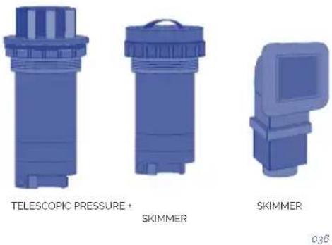
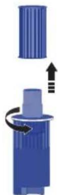
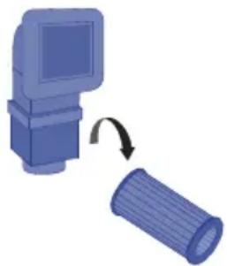
TELESCOPIC FILTER CLEANING
- Disconnect the electrical equipment. Differential in OFF position.
- Unscrew the top of the filter.
- Remove the cartridge.
- Clean the cartridge with water at low pressure.
FILTER PRESSURE CLEANING
- Disconnect the electrical equipment. Differential in OFF position
- Unscrew the cap on top of the filter.
- Release lock and unscrew the top of the filter.
- Remove the cartridge.
- Clean the cartridge with water at low pressure.
natural_image
Diagram showing a blue cylindrical object with an arrow indicating rotation or movement, no text or symbols present.

037
038
SKIMMER FILTER CLEANING
- Disconnect the electrical equipment. Differential in OFF position.
- Pull the top of the skimmer.
- Remove the cartridge.
- Clean the cartridge with water at low pressure.
natural_image
Illustration of a computer monitor and a cylindrical object with an arrow indicating rotation (no text or symbols)039
! ATTENTION
Remember to follow all the steps and to close the valve in order not to damage the Spa or hurt yourself.
6.4. Pre-filter of the pump maintenance
It is recommended to periodically check the condition of the pre-filter of the pump to avoid it from blocking. If debris has accumulated, the pre-filter should be opened and cleaned.
Follow these steps to clean the pre-filter:
- Turn off the Filtering Pump by placing the selector in the OFF position.
- Close the valve of the filtering circuit that connects the pump to the Spa.
- Using the key supplied with the equipment, turn the upper cover of the pre-filter anticlockwise until it becomes loose. Remove the basket of the pre-filter to clean it.
- Put the basket back into place. Place the joint of the cover to close it using the key.
- Open the filtering circuit valve.
6.5. Acrylic maintenance
Easy care for an elegant surface:
- Use common cleaners for general use. For normal care and cleaning, use a soft cloth or sponge with a little soap and water. Rinse it well, and dry with a clean, dry cloth. If you are using a household cleaner, please ensure it is recommended for acrylic surfaces by the manufacturer.
- Never use abrasive cleaners.
-
Do not allow the acrylic surface to come into contact with ketones or esters such as acetone, acetates (such as nail varnish remover, nail varnish or dry cleaning substances) or any organic solvent with chlorine, varnishes, petrol, aromatic solvents, etc.
-
Remove dust, smears and dry dirt with a soft, moist cloth.
- Clean off grease, oil, paint and ink stains with isopropyl alcohol and dry it with a clean, dry cloth.
- Avoid using razors or any other kind of sharp instrument that could scratch the surface. Small scratches can be removed by applying a fine layer of automotive varnish and lightly polishing it with a clean cloth.
Once a week, clean the area of the Spa which is not underwater with a quality polish for Spas.
! ATTENTION
Remember to never leave the Spa uncovered and exposed to sunlight, as this could cause damage not covered by the guarantee.
6.6. Light maintenance
Replacing the lamp is the only required maintenance on the spotlight. To replace the lamp, follow these steps:
- Dismantle the wooden side panel where the spotlight is installed using a medium-sized stecker screwdriver.
- To replace the lamp, turn the lamp-holder bushing anticlockwise and lift it from its position.
- Once the faulty lamp has been replaced, place the lamp-holder back in position and reassemble the wooden side panel of the Spa.
If you have any doubt about the explanation of this operation, contact your authorised dealer or authorised technical service.

WARNING- RISK OF ELECTRIC SHOCK
Make sure the power of the Spa is turned off.
The new lamp must have the same features as the lamp supplied.
Never install lamps without the front lens.
To ensure perfect watertightness, clean the mounting base of the flat gasket of the glass or replace it if you observe any dents or permanent damage.
6.7. Maintenance in periods of non-use or absence
SHORT PERIODS (3-5 days)
- Adjust the pH and treat the water (see Water Maintenance section).
- Cover the spa.
- Before using the Spa again, readjust the pH and treat the water again.
PROLONGED PERIODS (5-14 days)
- Set the temperature at its lowest level.
- Adjust the pH and treat the water (see Water Maintenance section).
- Cover the Spa.
- Before using the Spa again, reset the temperature as required, readjust the pH and treat the water again.
PREPARTING FOR THE WINTER PERIOD
If it is not planned to use the Spa through the winter season or for prolonged periods of time, the following operations should be done:
- Disconnect the electrical equipment, placing the differential switch tab in the OFF position.
- Locate the drain valve (see Drainage of the Spa) and turn the red lever of the valve to the OPEN position. The Spa will empty by gravity through the general drain.
- Leave the drain valve open.
- Remove the filter cartridge/s from the filter (See Maintenance of the filter) and keep in a dry place.
- Clean and dry the Spa.
- Cover the Spa.
Do not leave water in the Spa without electrical connection at temperatures below 0irc C, as the pipes can freeze and damage the spa.
! ATTENTION
Remember that when you drain your spa not all of the water runs off. If your spa is not going to be used for long periods, especially in winter, remove any stagnant water on the seats and on the bottom of the spa with a sponge. Any water remaining in the pipes can be sucked out through the water and air nozzles using a liquid suction pump. The pumps must also be emptied through the drain plug.
7. ERROR MESSAGES (TP600 & Touch control panels)
| Message Meaning | Action required | |
| Water Temperature is Unknown | After the pump has been running for 1 minute, the temperature will be displayed. | |
| Possible freezing condition | A potential freeze condition has been detected, or the Aux Freeze Switch has closed. | All water devices are activated. In some cases, pumps may turn on and off and the heater may operate during Freeze Protection.This is an operational message, not an error indication. |
| The water is too hot - M029 | The system has detected a spa water temp of 110°F (43.3°C) or more, and spa functions are disabled. | System will auto reset when the spa water temp is below 108°F (42.2°C). Check for extended pump operation or high ambient temp. |
| The water level is too low | This message can only appear on a system that uses a water level sensor. It appears whenever the water level get too low (or the water level sensor is disconnected) | Automatically disappears when the water level is adequate. Pumps and the heater turn OFF when this message appears. |
| The water flow is low - M016 | There may not be enough water flow through the heater to carry the heat away from the heating element. | Heater start up will begin again after about 1 min.See: **. |
| The water flow has failed - M017 | There is not enough water flow through the heater to carry the heat away from the heating element and the heater has been disabled. | See: **. |
| The heater may be dry - M028 | Possible dry heater, or not enough water in the heater to start it. The spa is shut down for 15 min. | See: **. |
| The heater is dry - M027 | There is not enough water in the heater to start it. The spa is shut down. | After the problem has been resolved, you must reset the message to restart heater start up.See: **. |
| The heater is too hot - M030 | One of the water temp sensors has detected 118°F (47.8°C) in the heater and the spa is shut down. | You must reset the message when water is below 108°F (42.2°C).See: **. |
| Flow-Related Checks | Check for low water level, suction flow restrictions, closed valves, trapped air, too many closed jets and pump prime. | |
| Sensors are out of sync - M015 | The temperature sensors MAY be out of sync by 3°F. | Call for Service if this message does not disappear within a few minutes. |
| Sensors are out of sync -- Call for service -- M026 | The temperature sensors are out of sync The fault above has been established for at least an hour. Call for service. See ** | |
| Sensor A Fault, Senor B Fault - Sensor A: M031, Sensor B: M032 | A temperature sensor or sensor circuit has failed. | If the problem persists, contact your vendor or a service engineer.See: **. |
| Communications error | The control panel is not receiving communication from the System. | If the problem persists, contact your vendor or a service engineer. |
| Test software installed | The Control System is operating with test software. | If the problem persists, contact your vendor or a service engineer. |
| Program memory failure - M022 | At Power-Up, the system has failed the Program Checksum Test. | This indicates a problem with the firmware (operation program) and requires a service call.See: **. |
| The settings have been reset (Persistent Memory Error) - M021 | Contact your service organization if this message appears on more than one power-up.See: **. | |
| The clock has failed - M020 | If the problem persists, contact your vendor or a service engineer.See: **. | |
| Configuration error (Spa will not Start Up) | If the problem persists, contact your vendor or a service engineer. | |
| A pump may be stuck on - M034 | Water may be overheated. POWER DOWN | THE SPA. DO NOT ENTER THE WATER. Contact your dealer or service organization. |
| Hot fault - M035 | A Pump Appears to have been Stuck ON when spa was last powered POWER DOWN THE SPA. | DO NOT ENTER THE WATER.If the problem persists, contact your vendor or a service engineer. |
** Some messages can be reset from the panel. Messages that can be reset will appear with a Clear Icon at the bottom of the Message Screen. Press the Clear Icon text to reset the message.
REMINDER MESSAGES
General maintenance helps: Reminder Messages can be suppressed by using the Reminders Screen. Reminder Messages can be chosen individually by the Manufacturer.
Check the pH : May appear on a regular schedule, i.e. every 7 days. Check pH with a test kit and adjust pH with the appropriate chemicals.
Check the sanitizer: May appear on a regular schedule, i.e. every 7 days. Check sanitizer level and other water chemistry with a test kit and adjust with the appropriate chemicals.
Clean the filter: May appear on a regular schedule, i.e. every 30 days. Clean the filter media as instructed by the manufacturer.
Change the water: May appear on a regular schedule. Change the water in the spa on regular basis to maintain proper chemical balance and sanitary conditions.
Clean the cover: May appear on a regular schedule. Vinyl covers should be cleaned and conditioned for maximum life.
Treat the wood: May appear on a regular schedule. Wood skirting and furniture should be cleaned and conditioned per the manufacturers instructions for maximum life.
Change the filter: May appear on a regular schedule. Filters should be replaced occasionally to maintain proper spa function and sanitary conditions.
Change the UV / Check the ozone: May appear on a regular schedule.
- PROBLEMS AND SOLUTIONS
| Problems Reasons Solutions | ||
| Insufficient flow of filtered water. | Filter is blocked by dirt. | Wash the filter. |
| The massage pump of the Jets does not work.Spa does not work. | The cable of the digital control panel is disconnected from the board.No electrical supply.Differential is disconnected. | Connect the cable to the board.Check that the pump is connected to the electric control panel.Connect the differential. |
| The massage pump of the airBlower does not work. | The cable of the digital control panel is disconnected from the board.No electrical supplyThe pump has disconnected owing to overheating. | Connect the cable to the board.Check that the pump is connected to the electric control panel.Let it cool for about 3 hours and then start-up the pump again. |
| Water leaks out through the Venturi.Jets are closed.Jets are not properly installed. The outer trim of the jet turns a quarter to open and close the water flow. If this trim makes a complete turn, it is not properly installed, and the jet will have to be removed and then placed correctly. | Open the jet.Remove the jet. Pull the outer trim about 2 cm. Unscrew the jet turning anti-clockwise. Once it has been dismantled, replace the jet, by screwing in a clockwise direction. Press the outer trim back into place. | |
| Limited airflow in the Jets. | Venturis are closed. | Open the Venturis. |
| Reduced airflow. Starter brushes of the motor are worn. | Change the pump. | |
| The water does not reach the required temperature. | Probe is damaged.Check programmed temperature. | Replace the temperature probe.Programme the temperature. |
Note: In the section 7. Error messages, you can finde the diagnosis messages meaning to solve possible breakdowns.
9. RECYCLING AND THE ENVIRONMENT
The Spa includes electric and/or electronic material, which at the end of its life-span, should be suitably treated as special waste.
Contact your local authorities to find out the collection and waste disposal procedure for electric and electronic material.
natural_image
Two recycling symbols: one with a recycling symbol and the other with an open bin (no text or labels)10. EVIDENCE OF CONFORMITY

IBERSPA, S.L.
N-II km 516,8
Carrer Projecte II
25200 - Cervera (Lleida)
SPAIN
ES PRODUCTOS: DA PRODUKTER:
EN PRODUCTS: S PRODUKTER:
DE PRODUKTE: FI TOUTTEET:
FR PRODUITS: N PRODUKTER:
IT PRODOTTI: GR ΠΙΡΙΟΝΤΑ:
PT PRODUTOS:
NL PRODUKTEN:
RU продукт:
SPAS PORTABLES CON
MUEBLE
PORTABLE SPAS WITH WOOD
CLADDING
EN - EVIDENCE OF CONFORMITY
The products listed above are in compliance with
2014/30/EU (Electromagnetic Compatibility), Directive 2014/35/EU (Low
Voltage) and with the European Standard: EN 17125:2018, EN 60335-
1:2012+AC+A11, EN 60335-2-60: 2005+A1+A11+A12+A2
FR - DECLARATION CONFORMITÉ
Signature/Qualification :
Signature/Qualification :
Firma/Qualifica :
Assinatura/Título :
Manager of Iberspa, S.L. by proxy
! ATENCIÓN
natural_image
Three abstract diagrams showing red X marks on blue rectangular blocks, one with a green checkmark (no text or symbols)natural_image
Two simple diagrams showing a solar panel with red X marks and a blue roof, one marked with a green checkmark (no text or symbols)natural_image
Technical line drawing of a vehicle chassis frame with structural components (no text or symbols)002
SWIMSPA
TRANSPORTE
A1. SWIMSPA - DESCARGA DEL CONTAINER

A2. SWIMSPA - DESCARGA DEL CONTAINER
1

natural_image
Illustration of a blue truck with a forklift and an arrow, no text or symbols present2

natural_image
Illustration of a truck with a forklift moving on a flatbed surface (no text or symbols)3

3.000 Ka
2 m

004
2

natural_image
Simple diagram of a train on a platform with a downward arrow indicating force or motion (no text or symbols)3


natural_image
Simple blue rectangular block resting on a surface with hatched ground lines (no text or symbols)
natural_image
3D diagram of a device interior with directional arrows indicating movement or force (no text or symbols)5
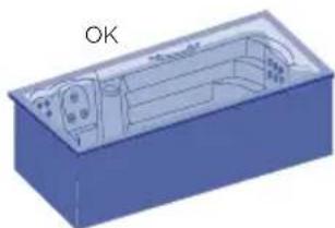
natural_image
3D diagram of a blue rectangular box with internal compartments and a labeled 'OK' (no text or symbols on the diagram itself)
natural_image
Illustration of a blue industrial device with red prohibition signs and a falling gear icon (no text or symbols)006
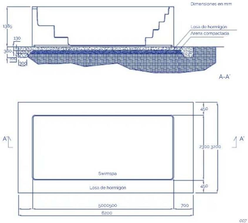
Notas:
natural_image
Pure electrical circuit lines without any symbols3

4

natural_image
Pure diagram of a syringe with internal components and an arrow indicating direction (no text or symbols)009
! ATENCIÓN
natural_image
Pure diagram of a blue square object with dimension lines and no text or symbols011
SPA PRIVADO CON DESBORDANTE
natural_image
Wooden square bathtub with white foam and black base (no text or symbols visible)012
natural_image
Illustration of a blue industrial robot with screw bolts and a warning symbol (no text or labels)013
021
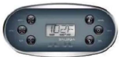
022
2 Speed pump
Calefactor
Foco
Bomba circulación
Bomba de masaje
Bomba de aire-turbo
Calefactor
Foco
Bomba circulación
2 Bomba de masajes
Calefactor
Foco
· AUX
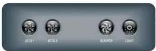
023
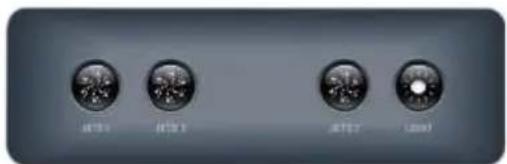
CONTROL DEL SISTEMA PARA TP600
Pantalla principal Pantalla principal
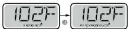
= Error normal o advertencia
= Recordatorio
natural_image
Simple illustration of a blue circular object with a curved arrow and plus sign, no text or symbols present.028
natural_image
Abstract graphic with a blue circular shape and a black plus sign, no text or symbols present.029
! ATENCIÓN
natural_image
Top-down view of a car with visible steering wheel, dashboard, and control panel (no text or symbols on the diagram itself)A - CONTROL CONTRACORRIENTE

Botón de la música


Botón de encendido
natural_image
Diagram of a mechanical component with arrows indicating motion or assembly (no text or symbols)037
natural_image
Blue mechanical component with three arrows indicating rotational motion (no text or symbols)038
LIMPIEZA DEL SKIMMER
natural_image
Illustration of a computer monitor and a cylindrical device with an arrow indicating rotation (no text or symbols)039
! ATENCIÓN
EN PRODUCTS: S PRODUKTER:
DE PRODUKTE: FI TOUTTEET:
FR PRODUITS: N PRODUKTER:
IT PRODOTTI: GR TIPIONTA:
PT PRODUTOS:
NL PRODUKTEN:
RU продукт:
SPAS PORTABLES CON
MUEBLE
PORTABLE SPAS WITH WOOD
CLADDING
EN - EVIDENCE OF CONFORMITY
The products listed above are in compliance with: 2014/30/EU (Electromagnetic Compatibility), Directive 2014/35/EU (Low Voltage) and with the European Standard: EN 17125:2018, EN 60335-1:2012+AC+A11, EN 60335-2-60: 2005+A1+A11+A12+A2
FR - DECLARATION CONFORMITÉ
natural_image
Three icons showing a blue container with red X marks, a blue container with red X marks, and a green checkmark (no text or symbols)201
INSTALLATION EN EXTERIEURS
natural_image
Two simple diagrammatic symbols: a red X with sun and light symbol, and a green checkmark over a blue container (no text or labels)001
natural_image
Technical line drawing of a vehicle chassis frame with structural components (no text or symbols)002
SWIMSPA
TRANSPORT
A1. SWIMSPA - TÉLÉCHARGEMENT DE CONTENEUR

A2. SWIMSPA - TÉLÉCHARGEMENT DE CONTENEUR
1

2

natural_image
Illustration of a forklift moving on a flatbed truck with tracks and equipment (no text or symbols)3

3.000 Ka
2 m
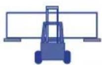
004
A3. SWIMSPA - DÉCHARGEMENT DU CAMION
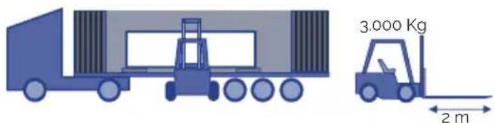
005
INSTALLATION
B. SWIMSPA - INSTALLATION
Dimensions & Weight:
Voir le document technique.
1
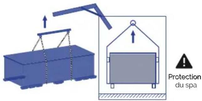
2
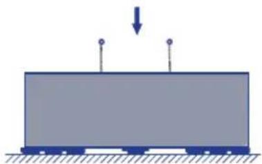
natural_image
Simple diagram of a rectangular block with two vertical posts and a downward arrow, no text or symbols present.3

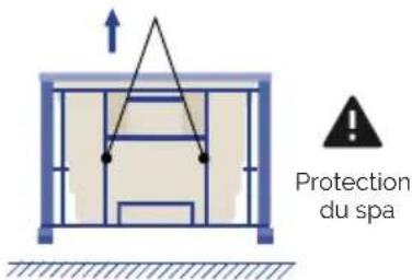
4

natural_image
Simple blue rectangular block resting on a surface with hatched ground lines (no text or symbols)
natural_image
3D diagram of a device interior with directional arrows indicating movement or force (no text or symbols)5

natural_image
3D diagram of a blue rectangular box with internal compartments and a labeled 'OK' (no text or symbols on the diagram itself)
natural_image
Illustration of a blue industrial device with red prohibition signs and a falling gear icon (no text or symbols)006

Observations:
natural_image
Simple diagram of a blue square object with dimension lines and a horizontal line, no text or symbols present.011
natural_image
Wooden square pool with white foam insulation and small circular buttons (no text or symbols visible)012
natural_image
Illustration of a blue robot with screw spools above and a warning symbol inside, no text or labels present.013
017
IMPORTANT
024
2 Pompe de massage
Pompe
Spot(s)
Pompe de massage
Spot(s)
Panneau tactile
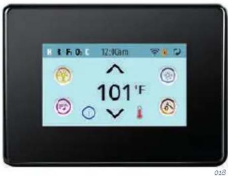
SYSTÈME DE CONTRÔLE POUR TP600
DOUBLE PLAGE DE TEMPÉRATURE (Élevé vs faible) | PANNEAU TACTILE
natural_image
Simple illustration of a blue sphere with a curved arrow and plus sign, no text or symbols present.028
natural_image
Simple graphic with a blue circular shape and a black plus sign, no text or symbols present.029
! ATTENTION
natural_image
Top-down view of a car with visible steering wheel and dashboard, labeled 'ACBDE' (no other text or symbols)A - CONTRÔLE CONTRE-COURANT
RECOMMANDATIONS DE NAGE:
natural_image
Diagram showing a blue cylindrical object being folded into a mechanical component with directional arrows indicating motion (no text or symbols)037
NETTOYAGE DE LA PRESSION DU FILTRE
natural_image
Blue mechanical component with three arrows indicating rotational motion (no text or symbols)038
NETTOYAGE DU FILTRE DE SKIMMER
natural_image
Illustration of a computer monitor and a cylindrical device with an arrow indicating rotation (no text or symbols)039
! ATTENTION
EN PRODUCTS: S PRODUKTER:
DE PRODUKTE: FI TOUTTEET:
FR PRODUITS: N PRODUKTER:
IT PRODOTTI: GR ΠΙΡΙΟΝΤΑ:
PT PRODUTOS:
NL PRODUKTEN:
RU продукт:
SPAS PORTABLES CON
MUEBLE
PORTABLE SPAS WITH WOOD
CLADDING
EN - EVIDENCE OF CONFORMITY
The products listed above are in compliance with: 2014/30/EU (Electromagnetic Compatibility), Directive 2014/35/EU (Low Voltage) and with the European Standard: EN 17125:2018, EN 60335-1:2012+AC+A11, EN 60335-2-60: 2005+A1+A11+A12+A2
FR - DECLARATION CONFORMITÉ
Signature/Qualification :
Signature/Qualification :
Firma/Qualifica :
Assinatura/Título :
Manager of Iberspa, S.L. by proxy
! ACHTUNG
natural_image
Three blue containers with red X marks and a green checkmark, no text or symbols presentnatural_image
Two simple diagrams showing a solar panel with red X marks and a blue roof, one marked with a green checkmark (no text or symbols)001
natural_image
Technical line drawing of a vehicle chassis frame with structural components (no text or symbols)SWIMSPA
TRANSPORT
A1. SWIMSPA - CONTAINER HERUNTERLADEN
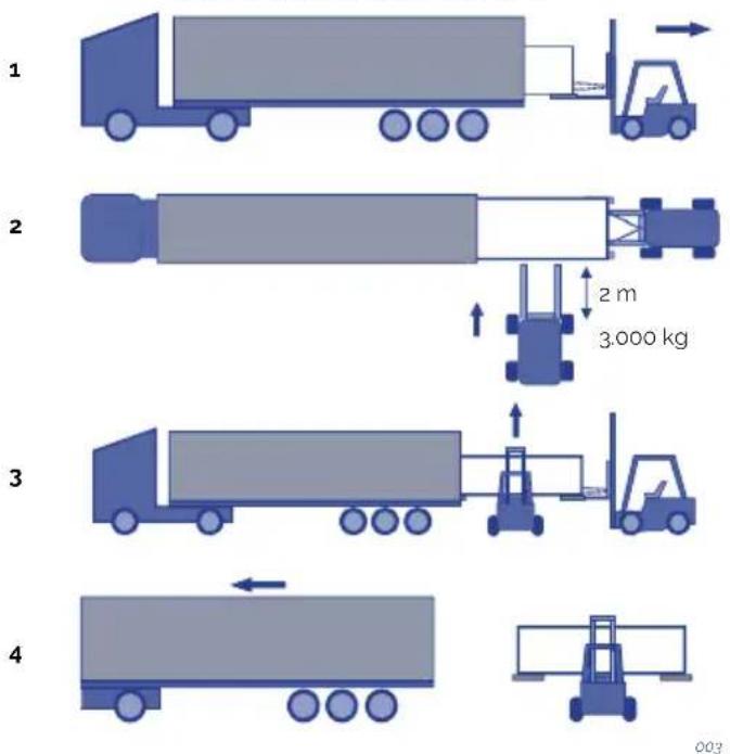
A2. SWIMSPA - CONTAINER HERUNTERLADEN
1

natural_image
Illustration of a blue truck with a forklift and an arrow, no text or symbols present2

natural_image
Illustration of a truck with a forklift moving on a flatbed surface (no text or symbols)3

3.000 Ka
2 m

004
A3. SWIMSPA - CONTAINER-DOWNLOAD

005
INSTALLATION
natural_image
Simple diagram of a train on a platform with a downward arrow indicating force or motion (no text or symbols)3


4
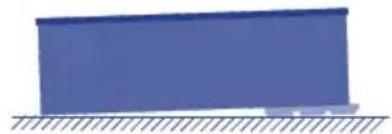
natural_image
Simple blue rectangular block resting on a surface with hatched ground lines (no text or symbols)
natural_image
3D diagram of a device interior with directional arrows indicating movement or force (no text or symbols)5

natural_image
3D diagram of a blue rectangular box with internal compartments and a labeled 'OK' (no text or symbols on the diagram itself)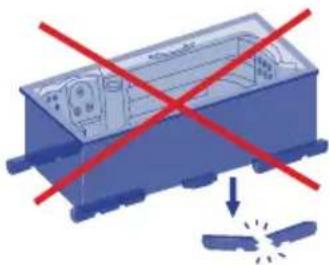
natural_image
Illustration of a blue industrial device with red prohibition signs and a falling gear (no text or symbols)006
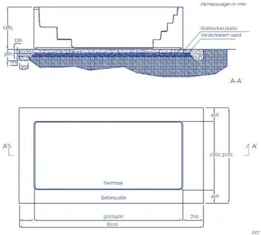
Anmerkungen:
natural_image
Simple diagram of a computer monitor with height dimension lines (no text or symbols)011
WHIRLPOOLS FÜR DEN PRIVATBEREICH MIT ÜBERLAUFRINNE
natural_image
Wooden square pool with white foam insulation and small white buttons (no text or symbols visible)012
natural_image
Illustration of a blue industrial robot with screw bolts and a warning symbol (no text or labels)013
INSTALLATION DES DIFFERENTIALSCHALTERS
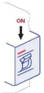
017
WICHTIG
021
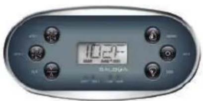
022
2 Speed pump
Heizung
Strahler(s)
Filterpumpe
Massagepumpen
026
027
natural_image
Blue 3D sphere with a curved arrow and plus sign, no text or symbols present028
natural_image
Blue circular object with concentric rings and a black plus sign pointing downward (no text or symbols)029
! ACHTUNG
natural_image
Top-down view of a car with visible steering wheel, dashboard, and control panel (no text or symbols on the diagram itself)

Musikknopf

Zündkissen
natural_image
3D diagram of a mechanical assembly with no visible text, numbers, or symbols
natural_image
Close-up of a blue mechanical component with ropes and brackets against a light blue background (no text or symbols visible)035
natural_image
Diagram showing a cylindrical object being inserted into a blue cylindrical component with an arrow indicating rotation (no text or symbols present)037
natural_image
Blue mechanical component with three arrows indicating rotational motion (no text or symbols)038
natural_image
Illustration of a computer monitor and a cylindrical device with an arrow indicating rotation (no text or symbols)039
! ACHTUNG
EN PRODUCTS: S PRODUKTER:
DE PRODUKTE: FI TOUTTEET:
FR PRODUITS: N PRODUKTER:
IT PRODOTTI: GR TIPIONTA:
PT PRODUTOS:
NL PRODUKTEN:
RU продукт:
SPAS PORTABLES CON
MUEBLE
PORTABLE SPAS WITH WOOD
CLADDING
EN - EVIDENCE OF CONFORMITY
The products listed above are in compliance with: 2014/30/EU (Electromagnetic Compatibility), Directive 2014/35/EU (Low Voltage) and with the European Standard: EN 17125:2018, EN 60335-1:2012+AC+A11, EN 60335-2-60: 2005+A1+A11+A12+A2
FR - DECLARATION CONFORMITÉ
Signature/Qualification :
Signature/Qualification :
Firma/Qualifica :
Assinatura/Título :
Manager of Iberspa, S.L. by proxy
! ATTENZIONE
natural_image
Three blue containers with red X marks and a green checkmark, no text or symbols presentnatural_image
Two simple illustrations: a blue box with red X marks and a blue storage container with a green checkmark (no text or symbols)001
natural_image
Technical line drawing of a vehicle chassis frame with structural components (no text or symbols)002
SWIMSPA
TRASPORTO
A1. SWIMSPA - SCARICO DEL CONTENITORE
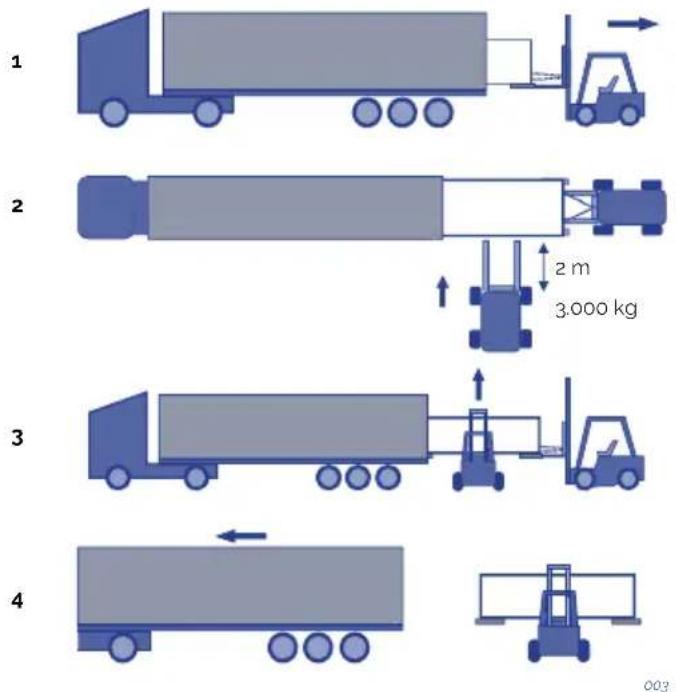
A2. SWIMSPA - SCARICO DEL CONTENITORE
1
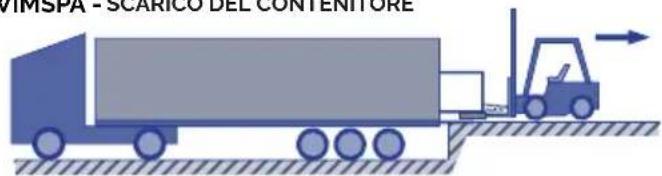
natural_image
Illustration of a blue truck with a forklift and an arrow, no text or symbols present.2

natural_image
Illustration of a forklift moving on a flatbed truck with tracks and equipment (no text or symbols)3

3.000 Ka
2 m

004
A3. SWIMSPA - SCARICA IL CAMION

005
INSTALLAZIONE
natural_image
Simple diagram of a train on a platform with a downward arrow indicating force or motion (no text or symbols)3
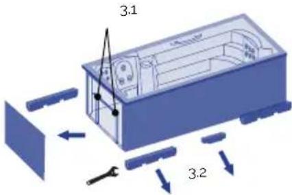

natural_image
Simple blue rectangular block resting on a surface with hatched ground lines (no text or symbols)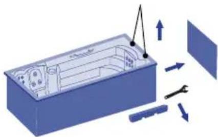
natural_image
3D diagram of a device interior with directional arrows indicating movement or force (no text or symbols)5

natural_image
3D diagram of a blue rectangular box with internal compartments and a labeled 'OK' (no text or symbols on the diagram itself)
natural_image
Illustration of a blue industrial device with red prohibition signs and a falling gear icon (no text or symbols)006

natural_image
Pure diagram of a blue square object with dimension lines and no text or symbols011
RIEMPIMENTO DI SPA RESIDENZIALI A SFIORO
natural_image
3D rendering of a wooden bathtub with white foam and small circular buttons (no text or symbols)012
natural_image
Illustration of a blue industrial robot with screw bolts and a warning symbol (no text or labels)013
017
IMPORTANTE
021

022
2 Speed pump
Riscaldatore
Faretto(i)
MODALITÀ PRONTO A RIPOSO | TP600
CICLI DI SPURGO | TP600
INTERVALLI DI DUE TEMPERATURE (ALTA E BASSA) | TOUCH SCREEN
natural_image
Blue circular object with a curved arrow and plus sign, no text or symbols presentnatural_image
Simple graphic with a blue circle, concentric rings, and a black plus sign with an arrow (no text or symbols)! ATTENZIONE
natural_image
Top-down view of a car with visible steering wheel, dashboard, and control panel (no text or symbols on the diagram itself)A - CONTROLLO CONTROCORRENTE

Pulsante musica


Tasto di accensione
natural_image
Diagram of a mechanical assembly with a cylindrical component and a base, showing motion arrows (no text or symbols)037
PULIZIA DEL FILTRO PRESSIONE:
natural_image
Diagram showing a blue plastic container with internal structure and directional arrows indicating rotation (no text or symbols)038
natural_image
Illustration of a blue mechanical component being processed with a cylindrical shaft (no text or symbols)039
! ATTENZIONE
EN PRODUCTS: S PRODUKTER:
DE PRODUKTE: FI TOUTTEET:
FR PRODUITS: N PRODUKTER:
IT PRODOTTI: GR II PIONTA:
PT PRODUTOS:
NL PRODUKTEN:
RU продукт:
SPAS PORTABLES CON
MUEBLE
PORTABLE SPAS WITH WOOD CLADDING
EN - EVIDENCE OF CONFORMITY
The products listed above are in compliance with : 2014/30/EU (Electromagnetic Compatibility), Directive 2014/35/EU (Low Voltage) and with the European Standard: EN 17125:2018, EN 60335-1:2012+AC+A11, EN 60335-2-60; 2005+A1+A11+A12+A2
FR - DECLARATION CONFORMITÉ
Signature/Qualification :
Signature/Qualification :
Firma/Qualifica :
Assinatura/Título :
natural_image
Three blue containers with red X marks and a green checkmark, no text or symbols presentnatural_image
Two simple icons: a blue box with red X marks and a blue roof with a green checkmark, both without any text or symbols.natural_image
Technical line drawing of a vehicle chassis frame with structural components (no text or symbols)002
SWIMSPA
TRANSPORTE
natural_image
Illustration of a blue truck with a forklift and cargo plane, no text or symbols present2

natural_image
Illustration of a forklift moving a large truck on a flatbed surface (no text or symbols)3

3.000 Ka
2 m

004
2
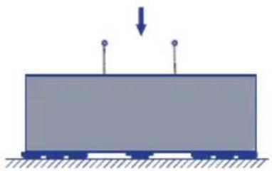
natural_image
Simple diagram of a rectangular block with two vertical posts and a downward arrow, no text or symbols present.3


natural_image
Simple blue rectangular block resting on a surface with hatched ground lines (no text or symbols)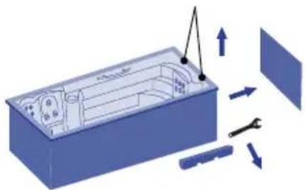
natural_image
3D diagram of a device interior with tool and directional arrows indicating movement (no text or symbols)5
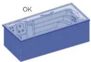
natural_image
3D diagram of a blue rectangular box with internal curved structure and labeled 'OK' (no text or symbols on the diagram itself)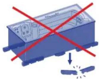
natural_image
Blue industrial component with red X-shaped prohibition signs and a small explosion symbol below (no text or labels)006
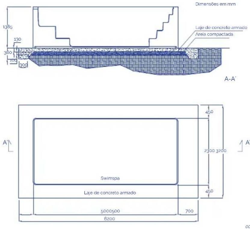
Notas:
natural_image
Pure diagram of a blue square object with dimension lines and no text or symbols011
ENCHIMENTO DE SPAS TRANSBORDANTES
natural_image
3D rendering of a wooden bathtub with white foam and small circular buttons (no text or symbols)012
natural_image
Illustration of a blue industrial robot with screw bolts and a warning symbol (no text or labels)013
Modo Teste (normalmente Off).
017

IMPORTANTE
DUPLA GAMA DE TEMPERATURA (ALTA/BAIXA) | TOUCH SCREEN
natural_image
Blue 3D sphere with a curved arrow and plus sign, no text or symbols presentCada tomada de ar acciona um determinado grupo de jets.
natural_image
Blue circular object with concentric rings and a black plus sign, no text or symbols present! ATENÇÃO
natural_image
Top-down view of a car with visible steering wheel, dashboard, and control panel (no text or symbols on the diagram itself)A - CONTROLO CONTRACORRENTE


Botão musica

Botão de ligado
natural_image
Diagram of a mechanical device with a cylindrical component and a rotating shaft, showing motion arrows (no text or symbols)037
natural_image
Blue mechanical component with three arrows indicating rotation or assembly (no text or symbols)038
natural_image
Illustration of a computer monitor and a cylindrical device with an arrow indicating rotation (no text or symbols)039
! ATENÇÃO
EN PRODUCTS: S PRODUKTER:
DE PRODUKTE: FI TOUTTEET:
FR PRODUITS: N PRODUKTER:
IT PRODOTTI: GR TIPIONTA:
PT PRODUTOS:
NL PRODUKTEN:
RU продукт:
SPAS PORTABLES CON
MUEBLE
PORTABLE SPAS WITH WOOD
CLADDING
EN - EVIDENCE OF CONFORMITY
The products listed above are in compliance with: 2014/30/EU (Electromagnetic Compatibility), Directive 2014/35/EU (Low Voltage) and with the European Standard: EN 17125:2018, EN 60335-1:2012+AC+A11, EN 60335-2-60: 2005+A1+A11+A12+A2
FR - DECLARATION CONFORMITÉ
- INLEIDING....335
- ALGEMENE WAARSCHUWINGEN....335
2. ALGEMENE WAARSCHUWINGEN
natural_image
Three icons showing a blue container with red X marks, a red cross on top, and a green checkmark on the right (no text or symbols)INSTALLATIE BUITENSHUIS
natural_image
Two simple icons: a blue box with red X marks and a blue roof with a green checkmark, both without any text or symbols.INSTALLATIE BINNENSHUIS
natural_image
Technical line drawing of a vehicle chassis frame with structural components (no text or symbols)SWIMSPA
VERVOER
A1. SWIMSPA - CONTAINER LOSSEN

A2. SWIMSPA - CONTAINER LOSSEN
1
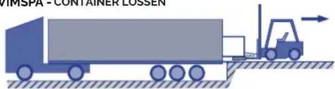
2

natural_image
Illustration of a truck with a forklift moving on a flatbed surface (no text or symbols)3

3.000 Ka
2 m

004
A3. SWIMSPA -LOSSEN VAN VRACHTWAGENS

005
INSTALLATIE
natural_image
Simple diagram of a rectangular block with two vertical posts and a downward arrow, no text or symbols present.3
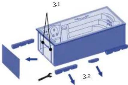
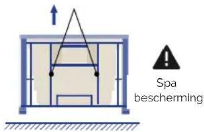
4

natural_image
Simple diagram of a blue rectangular block resting on a horizontal surface with diagonal hatching (no text or symbols)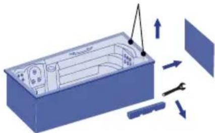
natural_image
3D diagram of a device interior with tool and directional arrows indicating assembly or operation (no text or symbols)5
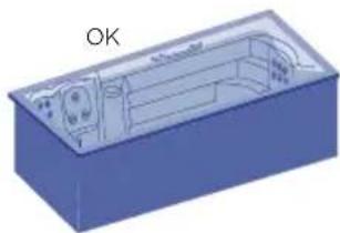
natural_image
3D CAD model of a blue rectangular housing with internal components and a labeled 'OK' (no text or symbols on the diagram itself)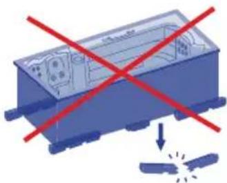
natural_image
Illustration of a blue industrial container with red prohibition signs and a downward arrow, symbolizing safety or hazard (no text present)006
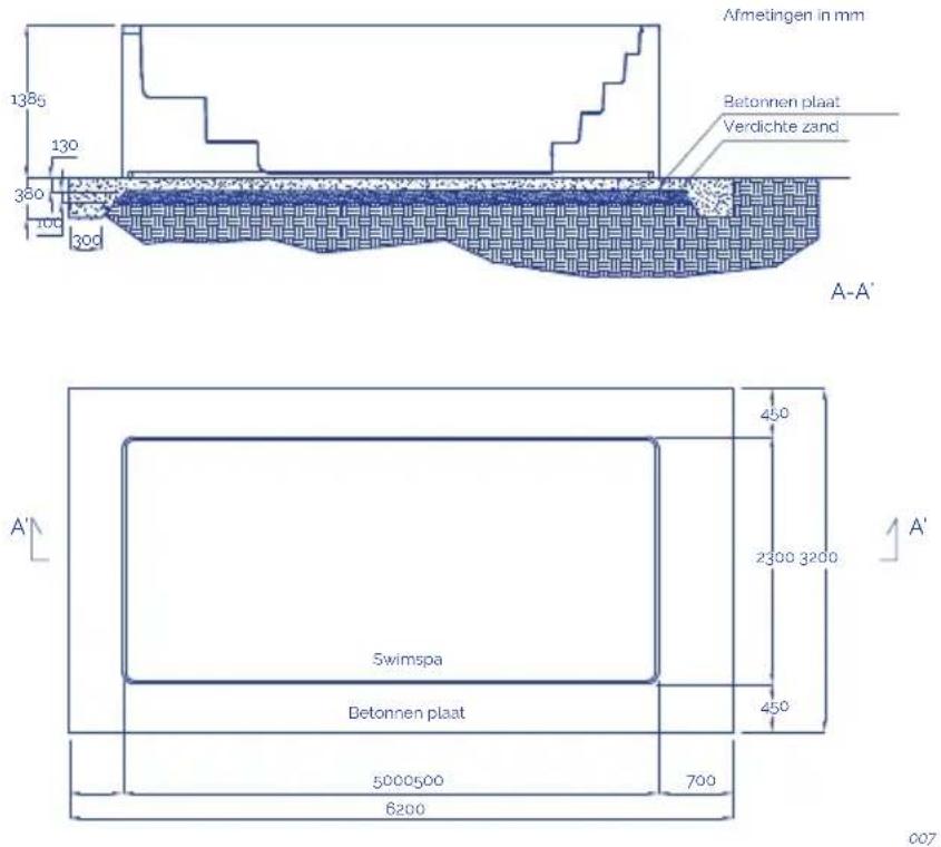
Opmerkingen:
flowchart
graph TD
    A["1: Long cylindrical component"] --> B["..."]
    B --> C["2: Shear-like component with rotational arrow"]
    C --> D["3: Circular component with rotation arrow"]
    D --> E["4: Long cylindrical component with rotational arrow"]
oo9
! AANDACHT
natural_image
Pure diagram of a blue square object with dimension lines and no text or symbols011
OPVULLEN VAN SPA'S MET OVERLOOPBEVEILIGING
natural_image
Wooden square bathtub with white foam insulation and small digital buttons (no text or symbols visible)012
natural_image
Illustration of a blue industrial robot with screw bolts and a warning symbol (no text or labels)013

AARDVERBINDING
017

BELANGRIJK
Win doktersadvies in.
5.2. Systemen
BESTAANDE SYSTEMEN
021
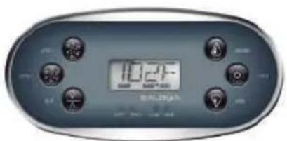
022
2 Speed pump
Verwarmingsinstallatie
Lamp(en)
Filterpomp
Massagepompen
Turbo blaaspomp
Verwarmingsinstallatie
Lamp(en)
Filterpomp
2 Massagepompen
Verwarmingsinstallatie
Lamp(en)
· AUX
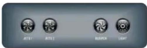
023
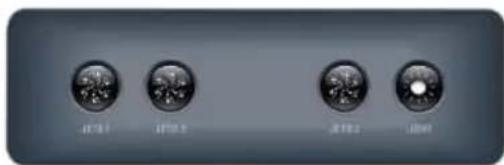
TEMPERATUUR AANPASSING | TP600
DUALE TEMPERATUURBEREIKEN (HOOG VS. LAAG) | TOUCH SCREEN
natural_image
Simple illustration of a blue circular object with a curved arrow and plus sign, no text or symbols present.natural_image
Top-down view of a car with visible steering wheel, dashboard, and control panel (no text or symbols on the diagram itself)ANTIVRIESBESCHERMING
natural_image
Diagram of a mechanical assembly with a cylindrical component and a rotating shaft (no text or symbols)037
DRUK FILTER SCHOONMAKEN:
natural_image
Diagram showing a blue mechanical component with arrows indicating rotational motion (no text or symbols)038
SKIMMER FILTER SCHOONMAKEN
natural_image
Blue 3D illustration of a mechanical component being processed by a cylindrical rod (no text or symbols)039
! AANDACHT
EN PRODUCTS: S PRODUKTER:
DE PRODUKTE: FI TOUTTEET:
FR PRODUITS: N PRODUKTER:
IT PRODOTTI: GR PIONTA:
PT PRODUTOS:
NL PRODUKTEN:
RU продукт:
SPAS PORTABLES CON
MUEBLE
PORTABLE SPAS WITH WOOD
CLADDING
EN - EVIDENCE OF CONFORMITY
The products listed above are in compliance with: 2014/30/EU (Electromagnetic Compatibility), Directive 2014/35/EU (Low Voltage) and with the European Standard: EN 17125:2018, EN 60335-1:2012+AC+A11, EN 60335-2-60: 2005+A1+A11+A12+A2
FR - DECLARATION CONFORMITÉ
Signature/Qualification :
Signature/Qualification :
Firma/Qualifica :
Assinatura/Título :
Manager of Iberspa, S.L. by proxy
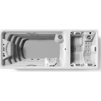
- Three-phase line 380V III BP21G1WL
- Three-phase line 400V BP013G1 & BP013G2
- ! ATTENTION
- CONTENTS
- INTRODUCTION
- GENERAL WARNINGS
- INSTALLATION AND ASSEMBLY
- Warnings
- Position and location of the spa
- OUTDOOR INSTALLATION
- INDOOR INSTALLATION
- PORTABLE LEVELLING SPAS
- SWIMSPA
- TRANSPORT
- INSTALLATION
- INGROUND VERSION
- Drainage
- Filling the spa
- PORTABLE SPA
- PORTABLE OVERFLOW SPA
- WARNING
- Electrical connection
- WARNING- RISK OF ELECTRIC DISCHARGE
- SPA CONNECTION STEPS
- INSTALLATION OF THE DIFFERENTIAL
- CONNECT THE ELECTRICAL CONTROL PANEL TO THE DIFFERENTIAL
- SWITCH
- DIP Switch Functions
- Assignable DIP Switches
- Special Features
- Default
- Feature
- CABLE SECTION
- Single line
- START-UP
- System start-up
- · TP-600
- · TOUCH PANEL
- PRE-SET FILTER CYCLES | TOUCH PANEL
- MAIN FILTRATION
- FILTER CYCLE 2 - OPTIONAL FILTRATION
- Water treatment
- pH ADJUSTMENT
- ATTENTION
- DISINFECTION OF THE WATER
- OPERATING INSTRUCTIONS
- Warnings on the use of the spa
- RISKS OF HYPERTHERMIA
- Systems
- EXISTING SYSTEMS
- · TP600
- · AUX
- ADJUSTING THE SET TEMPERATURE | TP600
- MODE READY & REST / READY IN REST MODE | TP600
- KEY
- READY-IN-REST MODE | TP600
- PRE-SET FILTER CYCLES | TP600
- PURGE CYCLES | TP600
- MEANING OF FILTER CYCLES | TP600
- CONTROL SYSTEM FOR Touch panel
- DUAL TEMPERATURE RANGES (High vs Low) | TOUCH PANEL
- PURGE CYCLES
- MEANING OF THE FILTER CYCLES
- Jets operation
- Swimspa controls
- Renewing the spa water
- Extras
- AROMATHERAPY
- AUDIO
- BLUETOOTH SOUND SYSTEM
- BLUETOOTH CONNECTION
- BLUETOOTH SCREEN
- ADJUST SETTINGS
- FITNESS KIT
- BENEFITS
- PROPER USE
- Notes:
- SWIMMING RECOMMENDATIONS:
- CARE INSTRUCTIONS
- ACCESSORIES
- ROW-EXERCISE
- MAINTENANCE
- Warnings
- Water maintenance
- ANTI-FREEZE PROTECTION
- SAFETY IN THE USE OF CHEMICAL PRODUCTS
- MAINTENANCE SCHEDULE OF THE SPA WATER
- USE OF SPECIAL PRODUCTS
- OZONE GENERATOR
- Filter maintenance
- TELESCOPIC FILTER CLEANING
- FILTER PRESSURE CLEANING
- SKIMMER FILTER CLEANING
- Pre-filter of the pump maintenance
- Acrylic maintenance
- Light maintenance
- WARNING- RISK OF ELECTRIC SHOCK
- Maintenance in periods of non-use or absence
- PREPARTING FOR THE WINTER PERIOD
- ERROR MESSAGES (TP600 & Touch control panels)
- REMINDER MESSAGES
- RECYCLING AND THE ENVIRONMENT
- EVIDENCE OF CONFORMITY
- EN - EVIDENCE OF CONFORMITY
- FR - DECLARATION CONFORMITÉ
- ! ATENCIÓN
- TRANSPORTE
- SPA PRIVADO CON DESBORDANTE
- CONTROL DEL SISTEMA PARA TP600
- LIMPIEZA DEL SKIMMER
- INSTALLATION EN EXTERIEURS
- IMPORTANT
- Panneau tactile
- SYSTÈME DE CONTRÔLE POUR TP600
- DOUBLE PLAGE DE TEMPÉRATURE (Élevé vs faible) | PANNEAU TACTILE
- RECOMMANDATIONS DE NAGE:
- NETTOYAGE DE LA PRESSION DU FILTRE
- NETTOYAGE DU FILTRE DE SKIMMER
- ! ACHTUNG
- WHIRLPOOLS FÜR DEN PRIVATBEREICH MIT ÜBERLAUFRINNE
- INSTALLATION DES DIFFERENTIALSCHALTERS
- WICHTIG
- ! ATTENZIONE
- TRASPORTO
- INSTALLAZIONE
- RIEMPIMENTO DI SPA RESIDENZIALI A SFIORO
- IMPORTANTE
- MODALITÀ PRONTO A RIPOSO | TP600
- CICLI DI SPURGO | TP600
- INTERVALLI DI DUE TEMPERATURE (ALTA E BASSA) | TOUCH SCREEN
- PULIZIA DEL FILTRO PRESSIONE:
- ENCHIMENTO DE SPAS TRANSBORDANTES
- DUPLA GAMA DE TEMPERATURA (ALTA/BAIXA) | TOUCH SCREEN
- ! ATENÇÃO
- ALGEMENE WAARSCHUWINGEN
- INSTALLATIE BUITENSHUIS
- INSTALLATIE BINNENSHUIS
- VERVOER
- INSTALLATIE
- Opmerkingen:
- ! AANDACHT
- OPVULLEN VAN SPA'S MET OVERLOOPBEVEILIGING
- AARDVERBINDING
- BELANGRIJK
- Systemen
- BESTAANDE SYSTEMEN
- TEMPERATUUR AANPASSING | TP600
- DUALE TEMPERATUURBEREIKEN (HOOG VS. LAAG) | TOUCH SCREEN
- ANTIVRIESBESCHERMING
- DRUK FILTER SCHOONMAKEN:
- SKIMMER FILTER SCHOONMAKEN
Brand : ASTRALPOOL
Model : Swimspa Méditerranea
Category : Spa