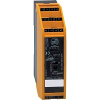
AC030S - Electric meter IFM - Free user manual and instructions
Find the device manual for free AC030S IFM in PDF.


User questions about AC030S IFM
0 question about this device. Answer the ones you know or ask your own.
Ask a new question about this device
Download the instructions for your Electric meter in PDF format for free! Find your manual AC030S - IFM and take your electronic device back in hand. On this page are published all the documents necessary for the use of your device. AC030S by IFM.
USER MANUAL AC030S IFM
CE
Operating instructions Safe AS-i output module
AC030S
Contents
1 Safety instructions .... 3
2 Installation / Set-up....4
3 Operating and display elements....6
4 Installation 6
5 Electrical connection....6
6 Response times....9
7 Consideration of the residual error probability to IEC 61508....10
8 Addressing....10
9 Programming....11
10 Operation....12
10.1 Diagnosis via ASIMON configuration software....12
11 Technical data....14
12 Approvals....16
13 Scale drawing....16
1 Safety instructions
Follow the operating instructions.
Non-observance of the instructions, operation which is not in accordance with use as prescribed below, wrong installation or handling can affect the safety of people and machinery.
For installation and prescribed use of the unit the notes in the operating instructions must be carefully observed and the applicable technical standards relevant for the application have to be considered.
In case of non-observance of notes or standards, specially when tampering with and/or modifying the unit, any liability is excluded.
The unit must be installed, connected and put into operation by a qualified electrician trained in safety technology.
After installation the system has to be subjected to a complete function check.
Disconnect the unit externally before handling it. Also disconnect any independently supplied relay load circuits.
For installation the requirements according to EN 60204-1 must be observed.
In case of malfunction of the unit please contact the manufacturer. Tampering with the unit can seriously affect the safety of operators and machinery. This is not permitted and leads to an exclusion of liability and warranty.
2 Installation / Set-up
Applications
The safe AS-i relay output module with conventional inputs is a decentralised output module for safe triggering of actuators in the AS-Interface Safety at Work system.
For this purpose, a code table with 7 x 4 bits is transmitted via the AS-i system; sent by the AS-i safety monitor (e.g. AC031S / AC032S) and received by the safe AS-i output module.
When operated correctly, the system can be used in applications up to performance level e according to EN ISO 13849-1 or IEC 61508/SIL3 (see notes Electrical connection).
Attention!

Depending on the safety components used the complete safety system can also be classified for a lower control category.
Function and electrical connection:
Observe all information in the description of the configuration software (e.g.
E7040S) and the operating instructions of the AS-i safety monitor. These documents provide all required instructions concerning installation, configuration, operation and maintenance of the AS-i safety system.
Information on the parameterizable safety functions of the safe AS-i output module can be found in the chapter "Monitoring devices" of the configuration software manual.
Important note:

The products described herein are designed to be components of a safety-oriented machine or control system. A complete safety-related system normally includes sensors, evaluation units, actuators and signalling components. It is the responsibility of each manufacturer of a machine or installation to ensure a correct functioning of the whole system. The manufacturer of the safe AS-i output module, his subsidiaries and affiliates are not in a position to evaluate all of the characteristics of a given machine or product.
The manufacturer accepts no liability for any recommendation that may be implied or stated herein.
The warranty contained in the contract of sale is the sole warranty. Any statements contained herein do not create new warranties or modify existing ones.
The complete description of the configuration software, the operating instructions of the AS-i safety monitor and the operating instructions of the safe AS-i output module must be taken into account!
Maintenance requirement

A minimum of one testing per year is compulsory by a demand on the safety function!
3 Operating and display elements

1: Slide switch R/P
2: Addressing plug
3: Combicon connector with screw terminals (option)
4 Installation
Install the safe AS-i output module on a 35 mm raised rail. The protection rating of the unit is IP20, therefore it should be mounted in a protected location with protection rating IP54 or higher (e.g. control cabinet).
The mounting orientation has no adverse effect on the function. Ensure that there is sufficient air circulation in the control cabinet.
5 Electrical connection
Mechanical switches or inductive sensors, for example, can be connected to the inputs. Connect the non-safe inputs e.g. with the screw terminals of the Combicon connectors.
Attention!
Do not connect the non-safe inputs to an external potential!
| Wiring | ||
| A+: | AS-i + |  |
| A-: | AS-i - | |
| I+: | sensor supply from AS-i (+24 V output) | |
| I-:: | sensor supply from AS-i (0 V) | |
| I1... I3 / 1. Y1: | non-safe switching inputs | |
| 13-14 / 23-24: | safe relay output | |
| LEDs 1: | switching status indication inputs / input feedback circuit | |
| LEDs 2: | AS-i, FAULT | |
| LEDs 3/4: | switching status indication code release / LED alarm output / process release | |
| ADR: | addressing interface | |
| R/P | slide switch run / programming mode | |
Wiring example safe relay output

Data bits
| Data bit | D3 | D2 | D1 | D0 |
| In/Out | 1. Y1 | I-3 | I-2 / O-2 | I-1 / O-1 |
| Activated inputs | Bit D3-D0 |
| I-1 | XXX1 |
| I-2 | XX1X |
| I-3 | X1XX |
| 1. Y1 | 1XXX |
| Activated alarm output | Bit D3-D0 |
| O-1 | XXX1 |
| Activated process output | Bit D3-D0 |
| O-2 | XX1X |
X = random
Parameter bits
| Parameter bit | P3 | P2 | P1 | P0 |
| default: | - | 1 | 1 | 1 |
| Parameter bit | Description |
| P0 | 1: input I10: auxiliary signal 1 (error reset)or auxiliary signal 2 (restart disable) |
| P1 | 1: process release0: process release via output O-2 = 1 |
| P2 | 1: feedback safe internal release0: input I3 |
The code words 0000, XX00 and 00XX cause the AS-i safety monitor to bring the installation into the safe state.
For more details on the effect of the data bits on the transmission sequence refer to the configuration software manual (see the chapter "Monitoring devices").

Note: safe relay output
The safe relay output is implemented with two positively driven relay contacts. If one of the two internal relays does not switch (e.g. due to fusing of the contacts), this is detected in the safe output module.
The relay contacts 13-14 and 23-24 are potential-free normally open contacts.
Attention!

The wiring influences the achievable control category.
The requirements for external wiring and the selection of the connected switching contacts refer to the functionality to be accomplished and to the required control category (EN 954-1 / ISO 13849-1 or EN/IEC 61508). The control category is either determined by means of a risk analysis (e.g. to EN 1050) or taken from a C standard. The control category or SIL level of the AS-i safety monitor must at least correspond to the control category or SIL level necessary for the application.
6 Response times
The response time of the safe AS-i relay output module to a safety request is maximum 50 ms from the application of the code sequence until the switch-off of the safe relays.
Calculation of the total response time
For the calculation of the response time of the total system, the response times of the other components also have to be added (mechanical switching contacts, data transmission, safety monitor and external relays or contactors possibly connected to the safe relay output).
Here, the switching times of the mechanical contacts (e-stops) and external relays or contactors possibly connected to the relay output of the output module have not been taken into account.
7 Consideration of the residual error probability to IEC 61508
To calculate the PFH (probability of a dangerous failure per hour) of a safety-related function the PFH values of all components used in this function must be taken into account.
The probability of failure on demand (PFD) is 9.25 × 10⁻⁶ / h .
The probability of a dangerous failure per hour (PFH) is 3.3 × 10⁻⁹ /h (per hour).
The indicated PFD and PFH values refer to the maximum switch-on time of 12 months.
The maximum service life (T) is 20 years. The unit can be used in applications up to SIL 3 (PLe / EN ISO 13849-1 or cat. 4 / EN954-1).
Explanation of the abbreviations:
PFD = probability of failure on demand
PFH = probability of a dangerous failure per hour
SIL = safety integrity level
T = life time (= service life)
The PFD / PFH values of the other components, especially of the AS-i safety monitor, can be found in the corresponding documentation.
8 Addressing
The safe AS-i output module can be addressed, when mounted and wired, via the addressing unit AC1154 with the cable (EVC076); the address is set to 0 at the factory.
A special feature of the safe AS-i output module are the two types of AS-i addresses:
- the safe AS-i address detects the communication on the safe address of the safety monitor and switches on the basis of the detected data.
- the non safety-related AS-i address serves for diagnosis and switching under normal operating conditions.
On delivery, all safe output modules with the same safe AS-i address switch in parallel. This can be changed by means of the parameter bits.
9 Programming
Programming of the safety-related AS-i address
- Set the switch on the unit to P (programming) (running light of the inputs I1-I3/1. Y1).
- Set the desired address with the addressing unit or the AS-i master.
- Check the programmed address with the addressing unit or the AS-i master.
- Check the ID code of the slave with the addressing unit or the AS-i master. The code should be "F".
- Check the ID1 code of the slave with the addressing unit or the AS-i master. The code should correspond to the tens digit of the address.
- Check the ID2 code of the slave with the addressing unit or the AS-i master. The code should correspond to the units digit of the address.
- Check the IO code of the slave with the addressing unit or the AS-i master. The code should be "7".
- When all steps from 3 to 7 have been carried out correctly, you can proceed with step 9. Otherwise, repeat from step 1.
- Set the switch of the unit to R (RUN).
Programming of the non safety-related AS-i address
This address can be programmed in the R position of the switch with the addressing unit or the AS-i master (green release LED flashes).
10 Operation
Check whether the unit operates correctly. Display by LEDs:
| • LEDs 1 yellow: | inputs switched |
| • LED 2 green: | voltage supply ok |
| • LED 2 red lit: | AS-i communication error, slave does not participate in the "normal" exchange of data, e.g. slave address 0 |
| • LED 2 red flashing: | peripheral fault, e.g. overload or short circuit of the sensor supply |
| • LED 3 red: | alarm output O-1 (non-safe)(through the host system the alarm output LED can be set as a static or dynamic output) |
| • LED 4 yellow: | process output O-2 (non-safe) |
| • LED 5 green: | release: code release |
| - off: | safe output relay switched off |
| - flashes, 1 Hz: | restart disable (auxiliary signal 2), waits for start signal; after start signal the safe output relay switches on |
| - flashes, 8 Hz: | waiting for error reset (auxiliary signal 1); when the safety monitor sends the signal "error reset", the safe output relay switches on |
| - lights: | safe output relay switched on |

If all LEDs flash quickly simultaneously, the unit has detected a fatal error.
This message is reset by briefly interrupting the supply voltage (Power On Reset).
Possible causes:
- faulty hardware
- status the unit cannot process
- overload of the internal relay
10.1 Diagnosis via ASIMON configuration software
In the configuration software ASIMON, the status of the safe output module can be visualised in the online diagnosis via the diagnostic block actuator diagnostics.
To do so, a corresponding diagnostic block is to be added for each safe output module in the ASIMON configuration.
The non-safe address of the output module AC030S as well as the diagnosis type must be added in this block. Two diagnosis types are available for the safe output module: type 2 and type 3:
Type 2: simple diagnosis -> on/off, visualisation green/red
Type 3: extended diagnosis -> on/off, error message, visualisation: green/red, flashing yellow
11 Technical data
| Electrical design | 4 non-safe inputs /2 non-safe LED outputs /1 safe relay output |
| Operating voltage | 26.5 ... 31.6 V DCSupply class 2 to cULus |
| Current consumption | ≤ 200 mA |
| Inputs | |
| Wiring | DC PNP |
| Input voltage range sensor | 18...30 V DC |
| Voltage supply | via AS-i |
| Short circuit detection | yes |
| Input current | typ. 10 mA |
| Sensor supply from AS-i | 24 V DC / 100 mA |
| LED output | |
| Supply via AS-i | yes |
| Integrated watchdog | yes |
| LED process output | |
| Power via AS-i | yes |
| Integrated watchdog | yes |
| Relay output | |
| Electrically separated | yes |
| Cross fault monitoring | no |
| Integrated watchdog | yes |
| Current rating per output | 3 A, 24 V, DC-13 or 3 A, 230 V, AC-15 |
| External supply | yes |
| Voltage range | 10...240 V AC / 24 V DC |
| Current rating per module | 3 A |
| LED function display | |
| Operation / fault / function | green / red / yellow |
| Operating temperature | -25...55°C |
| Protection | IP 20 |
| Overvoltage category | III |
| AS-Interface / extended addressing mode possible | version 2.1 / yes |
| AS-i profile | S-7. A. E |
| I/O configuration / ID code | 7 [Hex] / A. E [Hex] |
| AS-i certificate | pending |
| EMC | EN 50295 |
| Housing materials | PA |
| Dimensions (H x W x D) | 108 x 25 x 105 mm |
Additional technical specification for AC030S in context with cULus approval (UL508)
| Operating voltage | 30 V, 9 W |
| External protection | An isolated source with a secondary open circuit voltage < 30 V DC with a 3 amp maximum over current protection. Over current protection is not required when a Class 2 source is employed. |
| In general | UL mark does not provide UL certification for any functional safety rating or aspects of the above devices. |
| Current rating per output | Only for Class 2 power supplies |
| Voltage range |
12 Approvals
- cULus (UL508)
- TÜV Nord
13 Scale drawing


- 1 SAFETY INSTRUCTIONS
- 2 INSTALLATION / SET-UP
- 3 OPERATING AND DISPLAY ELEMENTS
- 4 INSTALLATION
- 5 ELECTRICAL CONNECTION
- 6 RESPONSE TIMES
- 7 CONSIDERATION OF THE RESIDUAL ERROR PROBABILITY TO IEC 61508
- 8 ADDRESSING
- 9 PROGRAMMING
- 10 OPERATION
- 10.1 DIAGNOSIS VIA ASIMON CONFIGURATION SOFTWARE
- 11 TECHNICAL DATA
- 12 APPROVALS
- 13 SCALE DRAWING
Brand : IFM
Model : AC030S
Category : Electric meter