
LDP100 - Optical particle monitor IFM - Free user manual and instructions
Find the device manual for free LDP100 IFM in PDF.
| Product type | Optical particle monitor |
| Model | IFM LDP100 |
| Measurement principle | Light obscuration (Class 1 laser) |
| Pressure range | Up to 420 bar |
| Required flow rate | 50 to 400 ml/min |
| Power supply | 9 to 33 V DC |
| Interfaces | CAN (CANopen, J1939), analog output 4-20 mA, digital input/output |
| Purity standards | ISO 4406:21, SAE AS 4059F, NAS 1638 |
| Display | Backlit LCD, green LED (on), red LED (alarm) |
| Operating temperature | Internal up to 85°C (temperature alarm) |
| Calibration | According to ISO 11943, traceable to NIST SRM 2806 |
| Protection | SELV/PELV, Class 1 laser |
| Mounting | Minimess M16x2 connections, bypass mounting |
| Maintenance | Cleaning with clean oil or isopropanol; no aggressive solvents |
| Repairability | Contact IFM after-sales service; calibration by manufacturer |
| Accessories | Only IFM accessories (www.ifm.com) |
| Fluid compatibility | Hydraulic oils, compatible with diesel, not compatible with phosphate ester/skydrol |
Frequently Asked Questions - LDP100 IFM
User questions about LDP100 IFM
0 question about this device. Answer the ones you know or ask your own.
Ask a new question about this device
Download the instructions for your Optical particle monitor in PDF format for free! Find your manual LDP100 - IFM and take your electronic device back in hand. On this page are published all the documents necessary for the use of your device. LDP100 by IFM.
USER MANUAL LDP100 IFM
9.6 Communication.... 23
9.6.1 Type 23
13.2.3 PDU Format 2....49
13.2.4.2 PDU 1 (addressed) 51
13.2.4.3 PDU 2 (Broadcast) 53
natural_image
Warning symbol with a triangle and radiating lines, no text or numbers present3 Usage prévu


flowchart
graph LR
    Pin6["Pin 6"] --> A["A"]
    Pin8["Pin 8"] --> A
    A -->|→| Pin8
bar
| X-Axis Label | Y-Axis Value | | :--- | :--- | | 1 | 20 | | 2 | 4 | | 3 | 15 | | 4 | 10 | | 5 | 8 | | 6 | 7 | | 7 | 6 | | 8 | 5 | | 9 | 4 | | 10 | 20 | The label '①' appears above the bars, possibly indicating a different measurement or condition. The x-axis is labeled 'X' with a value of 2. The y-axis is labeled 'y'. There is no additional data series present.| 19 | 17 | 15 | 13 | 11 | 9 | 7 | 5 | Current / mA | |
| 0 | 0 | 0 | 0 | -1 | -1 | -1 | -1 | Flow too lowERC0, Bit_10 | Bar 1 |
| 0 | 0 | -1 | -1 | 0 | 0 | -1 | -1 | Flow too highERC0, Bit_9 | |
| 0 | -1 | 0 | -1 | 0 | -1 | 0 | -111 | Error in measuring cellERC3, (Bit_0 v Bit_1 v Bit_2 v Bit_3) | |
| 0 | 000 | 0 | 0 | -1 | -1 | -1 | Concentration too lowERC0, Bit_14 | Bar 2 | |
| 0 | -1 | -1 | 0 | 0 | -1 | Concentration too highERC0, Bit_8 | |||
| 0 | -1 | 0 | -1 | 000 | -1 | 0 | -1 | Measurement result not plausible,Autoparts not reached ERC0, Bit_13 | |
| 0 | 0 | 0 | -1 | -1 | -1 | -1 | Conz. alarmERC3, Bit_14 | Bar 3 | |
| 0 | 0 | -1 | -1 | 0 | -1 | -1 | TalarmERC3, Bit_15 | ||
| 0 | -1 | 0 | -1 | -1 | 0 | -1 | ISO(i+1)>=ISO(i)ERC0, Bit_11 | ||
| Objet com. Initial | zing Pre-Operational Operational Stopped | ||
| PDO X | |||
| SDO X X | |||
| Synch X X | |||
| BootUp X | |||
| NMT X X X |
13.1.3 Service Data Object (SDO)
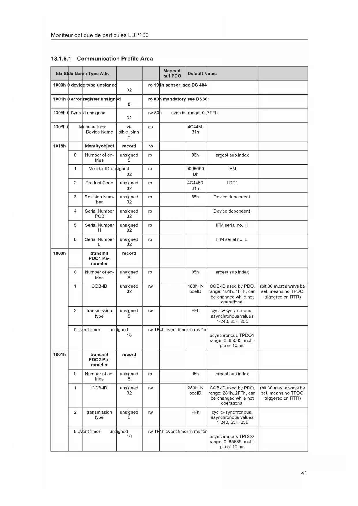
13.1.6.1 Communication Profile Area
| Idx S | Idx Name | Type Attr. | Mapped auf PDO | Default Notes | |||
| 1000h | device type unsigned | 32 | ro 19 | 4h sensor, see DS 404 | |||
| 1001h | error register unsigned | 8 | ro 00 | mandatory | see DS301 | ||
| 1005h | Sync d unsigned | 32 | rw 80h | sync id, range: 0..7FFh | |||
| 1008h | Manufacturer Device Name | visible_string | co | 4C445031h | |||
| 1018h | identityobject | record | ro | ||||
| 0 | Number of entries | unsigned 8 | ro | 06h | largest sub index | ||
| 1 | Vendor ID unsigned 32 | ro | 0069666Dh | IFM | |||
| 2 | Product Code | unsigned 32 | ro | 4C445031h | LDP1 | ||
| 3 | Revision Number | unsigned 32 | ro | 65h | Device dependent | ||
| 4 | Serial Number PCB | unsigned 32 | ro | Device dependent | |||
| 5 | Serial Number H | unsigned 32 | ro | IFM serial no. H | |||
| 6 | Serial Number L | unsigned 32 | ro | IFM serial no. L | |||
| 1800h | transmit PDO1 Parameter | record | |||||
| 0 | Number of entries | unsigned 8 | ro | 05h | largest sub index | ||
| 1 | COB-ID | unsigned 32 | rw | 180h+NodelD | COB-ID used by PDO, range: 181h..1FFh, can be changed while not operational | ||
| 2 | transmission type | unsigned 8 | rw | FFh | cyclic+synchronous, asynchronous values: 1-240, 254, 255 | ||
| 5 event timer unsigned 16 | rw 1F4h event timer in ms for | asynchronous TPDO1 range: 0..65535, multiple of 10 ms | |||||
| 1801h | transmit PDO2 Parameter | record | |||||
| 0 | Number of entries | unsigned 8 | ro | 05h | largest sub index | ||
| 1 | COB-ID | unsigned 32 | rw | 280h+NodelD | COB-ID used by PDO, range: 281h..2FFh, can be changed while not operational | ||
| 2 | transmission type | unsigned 8 | rw | FFh | cyclic+synchronous, asynchronous values: 1-240, 254, 255 | ||
| 5 event timer unsigned 16 | rw 1F4h event timer in ms for | asynchronous TPDO2 range: 0..65535, multiple of 10 ms | |||||
| Idx S | Idx Name Type Attr. | Mapped auf PDO | Default Notes | ||||
| 1802h | transmit | PDO3 Parameter | record | ||||
| 0 Number of entries | unsigned 8 | ro 05n largest sub index | |||||
| 1 COB-ID unsigned | 32 | rw 380h+N | odeID | COB-ID used by PDO, range: 381h..3FFh, can be changed while not operational | (bit 30 must always be set, means no TPDO triggered on RTR) | ||
| 2 transmission type | unsigned 8 | rw FFh cyclic+synchronous, | asynchronous values: 1-240, 254, 255 | ||||
| 5 event timer unsigned 16 | rw | 1F4h | event timer in ms for asynchronous TPDO3 range: 0..65535, multiple of 10 ms | ||||
| 1803h | Transmit PDO4 parameter | record | |||||
| 0 Number of entries | unsigned 8 | ro 05n largest sub index | |||||
| 1 COB-ID unsigned | 32 | rw 480h+N | odeID | COB-ID used by PDO, range: 481h..4FFh, can be changed while not operational | (bit 30 must always be set, means no TPDO triggered on RTR) | ||
| 2 transmission type | unsigned 8 | rw FFh cyclic+synchronous, | asynchronous values: 1-240, 254, 255 | ||||
| 5 event timer unsigned 16 | rw | 1F4h | event timer in ms for asynchronous TPDOI3 range: 0..65535, multiple of 10ms | ||||
| 1A00h | TPDOI1 Mapping Parameter | record | |||||
| 0 Number of entries | unsigned 8 | ro 05n largest sub index | |||||
| 1 | PDO Mapping for 1st app obj. to be mapped | co | 20000220h | Internal timestamp of the measurement, 4 bytes | |||
| 2 | PDO Mapping for 2nd app obj. to be mapped | co | 20010108h | ISO4μm, 1 byte in 2001h, sub 01 | |||
| 3 | PDO Mapping for 3rd app obj. to be mapped | co | 20010208h | ISO6μm, 1 byte in 2001h, sub 02 | |||
| 4 | PDO Mapping for 4th app obj. to be mapped | co | 20010308h | ISO14μm, 1 byte in 2001h, sub 03 | |||
| 5 | PDO Mapping for 5th app obj. to be mapped | co | 20010408h | ISO21μm, 1 byte in 2001h, sub 04 | |||
| 1A01h | TPDOI2 Mapping Parameter | record | |||||
| 0 Number of entries | unsigned 8 | ro 05n largest sub index | |||||
| Idx S | Idx Name Type Attr. | Mapped auf PDO | Default Notes | |||||
| 1A01h | PDO | Mapping for 1st app obj. to be mapped | unsigned 32 | co 2000022 | 0h | Internal timestamp of the measurement, 4 bytes | ||
| 2 PDO Mapping for 2nd app obj. to be mapped | unsigned 32 | co 20002010 | 8h | SAE4 μm, 1 byte in 2002h, sub 01 | ||||
| 3 PDO Mapping for 3rd app obj. to be mapped | unsigned 32 | co 20002020 | 8h | SAE6 μm, 1 byte in 2002h, sub 02 | ||||
| 4 PDO Mapping for 4th app obj. to be mapped | unsigned 32 | co 20002030 | 8h | SAE14 μm, 1 byte in 2002h, sub 03 | ||||
| 5 PDO Mapping for 5th app obj. to be mapped | unsigned 32 | co 20002040 | 8h | SAE21 μm, 1 byte in 2002h, sub 04 | ||||
| 1A02h | TPDO3 | Mapping Parameter | record | |||||
| 0 Number of entries | unsigned 8 | ro 05h largest sub index | ||||||
| 1 PDO Mapping for 1st app obj. to be mapped | unsigned 32 | co 20000012 | 0h | Operating hours, 4 bytes | ||||
| 2 PDO Mapping for 2nd app obj. to be mapped | unsigned 32 | co 20003010 | 8h | Oil status bits, 1 byte | ||||
| 3 PDO Mapping for 3rd app obj. to be mapped | unsigned 32 | co 20003070 | 8h | Measurement bits, 1 byte | ||||
| 4 PDO Mapping for 4th app obj. to be mapped | unsigned 32 | co 20003080 | 8h | Sensor status bits, 1 byte | ||||
| 5 PDO Mapping for 5th app obj. to be mapped | unsigned 32 | co 20004000 | 8h | Temperature 1 byte | ||||
| 1A03h | TPDO4 | Mapping Parameter | record | |||||
| 0 Number of entries | unsigned 8 | ro 03h largest sub index | ||||||
| 1 PDO Mapping for 1st app obj. to be mapped | unsigned 32 | co 20000022 | 0h | Internal timestamp of the measurement, 4 bytes | ||||
| 2 PDO Mapping for 2nd app obj. to be mapped | unsigned 32 | co 20006010 | 8h | NAS, 1 byte in 2006h, sub 01 | ||||
| 1F80h | NMT | Startup unsigned | 32 | rw 2 2 = no auto Operational | 0 = automatically switch to Operational can also be set via 2031h sub 01 | |||
| Idx Sldx | Idx Name | Type Attr. | Mapped auf PDO | Default Notes | ||||
| 2000h | Time related parameters of the sensor | record | ||||||
| 0 Number of entries | unsigned 8 | ro 04h largest sub index | ||||||
| 1 Operating hours | unsigned 32 | ro y Sensor up time in se- | conds | |||||
| 2 Timestamp of the last measurement | unsigned 32 | ro y Timestamp of the last | measurement | |||||
| 3 Laser operating time in hours | unsigned 32 | ro Operating hours of the | laser | |||||
| 4 | reserved | unsigned 32 | ro | Time to next calibration - disabled for LDP100 Time to threshold to S1 | ||||
| 2001h | ISO measurement | record | ||||||
| 0 Number of entries | unsigned 8 | ro 04h largest sub index | ||||||
| 1 | ISO4 μm unsigned 8 | ro | y | |||||
| 2 | ISO6 μm unsigned 8 | ro | y | |||||
| 3 | ISO14 μm | unsigned 8 | ro | y | ||||
| 4 | ISO21 μm | unsigned 8 | ro | y | ||||
| 2002h | SAE measurement | record | ||||||
| 0 Number of entries | unsigned 8 | ro 04h largest sub index | ||||||
| 1 SAE4 μm unsigned 8 | ro y | Offset of two to display 000, 00 and 0, valid to all classes 0 = SAE 000 1 = SAE 00 2 = SAE 0 3 = SAE 1 4 = SAE 2 ...... | ||||||
| 2 SAE6 μm unsigned 8 | ro | y | ||||||
| 3 | SAE14 μm | unsigned 8 | ro | y | ||||
| 4 | SAE21 μm | unsigned 8 | ro | y | ||||
| 2003h | Condition Monitoring Bitfield | array | ||||||
| 0 Number of entries | unsigned 8 | ro 08h largest sub index | ||||||
| Idx Sldx Name Type Attr. | Mapped auf PDO | Default Notes | ||||||
| 2003h | Oil specific bits | unsigned 8 | ro y 0 | Concentration limit | exceeded1 Flow rate high2 Flow rate low3 Measured values not plausible (air...)4 Auto mode: Meas-Time reached5 Autoparts not reached6 Concentration too low | 0: C>= ISO 231: F>5002: F<503: ISO(i+1)>= ISO(i)4: meas_time>= 3005: parts < autoparts6: C <= ISO 9 | ||
| 2 reserved unsigned | 8 | ro | ||||||
| 3 reserved unsigned | 8 | ro Calibration hint - di- | sabled for LDP100Bit 0: Threshold S1 reachedBit 1: Threshold S5 reached | |||||
| 4 reserved unsigned | 8 | ro | ||||||
| 5 reserved unsigned | 8 | ro | ||||||
| 6 reserved unsigned | 8 | ro | ||||||
| 7 Measurement info | unsigned 8 | ro y Bit0: Measurement run- | ningBit1: Measurement mode: Time controlledBit2: Measurement mode: Digital I/OBit3: Measurement mode: ManualBit4: Alarm type: (1) Filter / (0) StandardBit5: Power-UpBit6: Alarm concentration (corresponds to the alarm LED being switched on)Bit7: Temperature alarm | Bit 6 and 7: corresponds to the alarm LED being switched on and the open collector pin | ||||
| 8 Sensor alarm unsigned | 8 | ro y Bit0: Laser current high | Bit1 Laser current lowBit2: Photovoltage highBit3: Photovoltage lowBit4: Temperature highBit5: Temperature lowBit6: -Bit7: Measuring mode: Auto | 0: I>2,8 mA1: I<1 mA2: U>4 V3: U<4 V4: T>80°C5: T<-20°C | ||||
| 2004h | sensor temperature | signed 8 | ro y | temperature in °C | ||||
| 2005h | flow index unsigned | 16 | ro | Flow index (0..500) | ||||
| 2006h | NAS measurement | record | ||||||
| number of entries | unsigned 8 | ro | 01h | largest sub index | ||||
| Idx S | Idx Name Type Attr. | Mapped auf PDO | Default Notes | |||||
| 2006h | NAS | unsigned | 8 | ro y offset of one to display | 00 and 00 = NAS 001 = NAS 02 = NAS 1...13 = NAS 12 (maximum value) | |||
| 2020h | command | unsigned | 8 | wo 1 = start a measure- | ment2 = stop a measurement3 = intermediate result | |||
| 2030h | measurement related settings | record | ||||||
| 0 Number of entries | unsigned 8 | ro 4h largest sub index | ||||||
| 1 measurement time | unsigned 32 | rw | Measurement Time in s | |||||
| 2 | hold time | unsigned 32 | rw | Time between Measurements | ||||
| 3 | operation mode | unsigned 16 | rw | 0 = time Control1 = digital I/O2 = button3 = automatic | ||||
| 4 | History disable | unsigned 16 | rw | 0h | 0 = history enabled1 = history disabled | |||
| 2031h | startup settings | record | ||||||
| 0 Number of entries | unsigned 8 | ro 4h largest sub index | ||||||
| 1 | Startmode | unsigned 16 | rw | 0h | 0 = Network with NMT Master (Init => PreOp => Start_Remote_Node => Operational)>0 = Network without NMT Master (Init => Operational)can also be set via 1F80h sub 00 | |||
| 2 | Communication type | unsigned 16 | rw | Enabled communication interface:0: reserved1: CANopen2: auto3: J1939 | ||||
| 3 Baudrate CAN | unsigned 16 | rw | Baudrate CAN:3: 125k4: 250k5: 500k6: 1000k | |||||
| 2032h | standard & alarm related settings | record | ||||||
| Idx Sldx Name Type Attr. | Mapped auf PDO | Default Notes | ||||
| 2032h | 0 Number of entries | unsigned 8 | ro 9h | largest sub index | ||
| 1 Display & Alarm Standard | unsigned 16 | rw Displayed Standard | and Alarm Trigger Bit Setting0 = ISO1 = SAE2 = NAS | |||
| 2 Alarm Type unsigned | 16 | rw 0 = standard alarm | 1 = filter mode | |||
| 3 Temperature alarm value | unsigned 8 | rw Value range: 0..85 °C | 0 = deactivated | |||
| 4 | ISO/SAE4 μm | unsigned 8 | rw | alarm threshold 4 μm | ||
| 5 | ISO/SAE6 μm | unsigned 8 | rw | alarm threshold 4 μm | ||
| 6 ISO/SAE14 μm | unsigned 8 | rw | alarm threshold 4 μm | |||
| 7 ISO/SAE21 μm | unsigned 8 | rw | alarm threshold 4 μm | |||
| 8 NAS unsigned | 8 | rw | alarm threshold NAS | |||
| 2100h | 0 readmem control functions | record | ||||
| 0 Number of entries | unsigned 8 | ro 4h | largest sub index | |||
| 1 | Size of history memory | unsigned 32 | ro | device dependand | ||
| 2 | Used history mem | unsigned 32 | ro | used datasets within memory (corresponds internally to write pointer) | ||
| 3 | Reading pointer, dataset | unsigned 32 | rw | autoincrementing read pointer to a dataset for history memory reading; can be between 0 and current write pointer | ||
| 4 | Clear history memory | unsigned 16 | wo | 1 = clear memory | ||
| Idx SIdx | Idx Name | Type Attr. | Mapped auf PDO | Default Notes | |||
| 2101h | 0 | readmem Initiate segmented SDO data upload | unsigned 32 | ro Appropriate | Pointer | has to be set (with 2100sub3) before start reading,Size of the record will be sent back on reading | This initiates a standardised "segmented SDO upload". Please note: change a toggle bit for each data set and set the corresponding bit at the endset the corresponding bit at the end of the complete transferhttp://www.canopen-solutions.com/english/about_canopen/device_configuration_canopen.shtml |
13.2 CAN J1939
| PGN SPN length (Bit) SPN | Name Description Units | |||
| 0xFF02 8 520201 NAS Contamination represented as | NAS standard: Offset of one in order to represent 00 and 0, valid for all classes0 = NAS 001 = NAS 02 = NAS 13 = NAS 24 == NAS 3......13 = NAS 12 (maximum value) | Ordinal numeral | ||
| 0xFF02 8 520202 reserved | ||||
| 0xFF03 32 520203 Current internal time (operating hours, in seconds) | Current internal operating time seconds | |||
| 0xFF03 8 520204 Oil state bits | Bit 0: concentration threshold | exceeded (>= ISO 23)Bit 1: high flow (>500 ml/min)Bit 2: low flow (<50 ml/min)Bit 3: measurements not plausible (e.g. air, ISO(i+1)>=ISO(i)) | ||
| 0xFF03 8 520205 | Measure state bits | Bit 0: measurement in progress | Bit 1: measurement type (time controlled)Bit 2: measurement type I/O (digital input)Bit 3: measurement type manual (Button/CANopen/J1939)Bit 4: Alarm mode: Filter / StandardBit 5: Power-UpBit 6: Alarm concentration (corresponds with alarm-LED)Bit 7: temperature alarm triggered | |
| 0xFF03 8 520206 | Sensor status bits | Bit 0: Laser current high(I >2,8 mA)Bit 1: Laser current low (I <1 mA)Bit 2: Photodiode voltage high (U >4 V)Bit 3: Photodiode voltage low (U <4 V)Bit 4: Temperature high (T >80 °C)Bit 5: Temperature low (T < -20 °C)Bit 6: -Bit 7: Measurement mode: Auto | ||
| 0xFF03 8 520207 | Temperature | Device temperature resolution1 bit/KOffset: 40 °C (0 = -40 °C; 40 = 0 °C; 140 = 100 °C) | °C | |
| 0xFF04 24 520208 | PCB Serial number | Serial number | ||
| 0xFF04 12 520209 | Current measurement timein seconds | Current measurement time in seconds (range: 0x0..0xFFFF, maximum value 3599 seconds) | seconds | |
| 0xFF04 20 520210 | Delay time between two measurements in seconds | Delay time between two measurements in seconds (Range: 0x1..0x1517F, corresponds to 1-86399 seconds) | seconds | |
| PGN SPN length (Bit) SPN | Name Description Units | ||
| 0xFF04 8 520211 Findex/2000 | Current Flowindex (set or calcu- | lated) | |
| 0xFF05 32 520212 Laser operating time Laser operating time in seconds | |||
| 0xFF05 32 520213 reserved | |||
| 0xFF06 8 520214 Partikel 4 μm | Particles in 4 μm class in current | measurement =(LOG2(concentration)+1)*10 | |
| 0xFF06 8 520215 Partikel 6 μm | Particles in 6 μm class in current | measurement =(LOG2(concentration)+1)*10 | |
| 0xFF06 8 520216 Partikel 14 μm | Particles in 14 μm class in cur- | rent measurement =(LOG2(concentration)+1)*10 | |
| 0xFF06 8 520217 Partikel 21 μm | Particles in 21 μm class in cur- | rent measurement =(LOG2(concentration)+1)*10 | |
13.2.4.2 PDU 1 (addressed)
| Device address (Node ID) | 32 | Parameter | |||||||||||||||
| Type | Direction | Prio | R | DP | PF | PS | SA | PGN | 29Bit ID (hex) | Byte 0 | Byte 1 | Byte 2 | Byte 3 | Byte 4 | Byte 5 | Byte 6 | Byte 7 |
| PDU1 | Rx | 7 | 0 | 0 | 239 | 32 | 0 | 0xEF20 | 0x1CEF2000 | 1 | Start and stop measurement (F in measurement mode 2)1 = Start of a measurement2 = Stop of a measurement3 = immediate result | ||||||
| PDU1 | Rx | 7 | 0 | 0 | 239 | 32 | 0 | 0xEF20 | 0x1CEF2000 | 2 | Measurement mode0 = Time Control1 = Digital I/O-Pin2 = Button/CANopen/J1309 Control3 = Automatic | ||||||
| PDU1 | Rx | 7 | 0 | 0 | 239 | 32 | 0 | 0xEF20 | 0x1CEF2000 | 3 | History disable0 = History enabled1 = History disabled | ||||||
| PDU1 | Rx | 7 | 0 | 0 | 239 | 32 | 0 | 0xEF20 | 0x1CEF2000 | 4 | Measurement time in seconds (Range: 0x1E, 0x12C; corresponds to 30-300 seconds) | Delay time between two measurements in seconds (Range: 3x1, 3x15/7F; corresponds to 1-80368 seconds) | |||||
| PDU1 | Rx | 7 | 0 | 0 | 239 | 32 | 0 | 0xEF20 | 0x1CEF2000 | 5 | Amount of measurements used for arithmetic mean of concentration Alarm | Alarm Type0 = Standard Mode1 = Filter Mode | Display & Alarm Standard Displayed Standard and Alarm Trigger Bit Setting0 = ISO1 = SAE2 = NAS | ||||
| Device address (Node ID) | 32 | Parameter | |||||||||||||||||
| Type | Direction | Prior | R | DP | PF | PS | SA | PGN | 29BIT ID | (hex) | Byte 0 | Byte 1 | Byte 2 | Byte 3 | Byte 4 | Byte 5 | Byte 6 | Byte 7 | |
| PDU1 | Rx | 7 | 0 | 0 | 239 | 32 | 0 | 0xEF20 | 0x1CEF2000 | 8 | ordinal numeral (ISO/SAE) for alarm at 4 μm | ordinal numeral (ISO/SAE) for alarm at 14 μm | ordinal numeral (ISO/SAE) for alarm at 21 μm | ||||||
| PDU1 | Rx | 7 | 0 | 0 | 239 | 32 | 0 | 0xEF20 | 0x1CEF2000 | 7 | ordinal numeral NAS for alarm | ||||||||
| PDU1 | Rx | 7 | 0 | 0 | 239 | 32 | 0 | 0xEF20 | 0x1CEF2000 | 8 | reserved | ||||||||
| PDU1 | Rx | 7 | 0 | 0 | 239 | 32 | 0 | 0xEF20 | 0x1CEF2000 | 9 | Alarm threshold temperature, range: 0.85°C0 = deactivated | ||||||||
| PDU1 | Rx | 7 | 0 | 0 | 239 | 32 | 0 | 0xEF20 | 0x1CEF2000 | 10 | enable communication interface:0: reserved1: CANopen2: auto3: J1909 | ||||||||
| PDU1 | Rx | 7 | 0 | 0 | 239 | 32 | 0 | 0xEF20 | 0x1CEF2000 | 11 | CAN-Statistic:3: 125x 4: 250x 5: 500x 6: 1000x | ||||||||
| PDU1 | Rx | 7 | 0 | 0 | 239 | 32 | 0 | 0xEF20 | 0x1CEF2000 | 12 | reserved | ||||||||
| PDU1 | Rx | 7 | 0 | 0 | 239 | 32 | 0 | 0xEF20 | 0x1CEF2000 | 13 | CAN Node-ID | ||||||||
| PDU1 | Rx | 7 | 0 | 0 | 239 | 32 | 0 | 0xEF20 | 0x1CEF2000 | 14 | CAN Terminator0 = off1 = on | ||||||||
| Device address (Node ID) | 32 | Parameter | |||||||||||||||
| Type | Direction | Prio | R | DP | PF | PS | SA | PGN | 29Bit ID (hex) | Byte 0 | Byte 1 | Byte 2 | Byte 3 | Byte 4 | Byte 5 | Byte 6 | Byte 7 |
| POU1 | Rx | 7 | 0 | 0 | 239 | 32 | 0 | 0xEF20 | 0x1CEF2000 | 15 | Flow in deciled mode, if 0 is set, the device calculates the flow automatically, if range between 50 and 500, flow is fixed to the value | ||||||
| POU1 | Rx | 7 | 0 | 0 | 239 | 32 | 0 | 0xEF20 | 0x1CEF2000 | 16 | Amount of particles to be detected in automatic mode | ||||||
| POU1 | Rx | 7 | 0 | 0 | 239 | 32 | 0 | 0xEF20 | 0x1CEF2000 | 17 | Mask for PGNs of PDU2 format to be send, if bit (value of which corresponds with PS of POU2) is TRUE, then the PGN will be send e.g.: 0x000F switches on the SPN | transmission interval of all PGNs of PDU2 format in seconds0 = as soon as new value is available>0 = interval in seconds (Default = 10) | |||||
| POU1 | Rx | 7 | 0 | 0 | 239 | 32 | 0 | 0xEF20 | 0x1CEF2000 | 250 | 0x55 = Refort the device | ||||||
13.2.4.3 PDU 2 (Broadcast)
| Device address (Node ID): | 32 | ||||||||||||||||
| Type | Direction | Priority | R | DP | PF | PS SA | PCN | 208-10 (free) | Byte 5 | Byte 1 | Byte 2 | Byte 3 | Byte 4 | Byte 5 | Byte 6 | Byte 7 | |
| FDU2 | Tx | 7.0 | 0 | 255 | 0 | 32 | DFF00 | 0xCF0020 | Internal time stamp of the measurement | ISO 4pm | ISO 5pm | ISO 7pm | ISO 21pm | ISO 21pm | |||
| FDU2 | Tx | 7 | 0 | 255 | 1 | 32 | Cell-101 | 0xCF10100 | Internal time stamp of the measurement | 504.4pm | 504.5pm | 504.11pm | 504.21pm | 504.21pm | |||
| SAE Standard coding: Offset of low in order to approximate 000, 00 and 0, walk in all channels0 = SAE 000, 1 = SAE 00, 2 = SAE 0, 3 = SAE 1, 4 = SAE 2 | |||||||||||||||||
| FDU2 | Tx | 7 | 0 | 255 | 2 | 32 | Cell-100 | 0xCF1020 | Internal time stamp of the measurement | measured | NAS | ||||||
| FDU2 | Tx | 7 | 0 | 255 | 9 | 32 | DFF00 | 0xCF0020 | Current signal line spacing four. In second | Off state bits | Measure state bits | Sensor status bits | Temperature | ||||
| B10, concentration, measured around 10 - ISO 251B11 High flow (>500 ml/minB12 Low flow) (GB/cm2)B13 measurement, not pulse rate (e.g., 100) *1/(100cm) | B10 measurement in progress(0.1 measurement type data enclosed)(0.12 measurement type IO (pathable power)B12 measurement type manual(Extrusion/CAV/Type I/1935)B13 Gamma mode Filter StandardsB14 Pressure B16 Alarm re-coumation (consequences with alarm LED)B17 Temperature alarm triggered | B10 Laser current Nigh (≥2.5mA)(0.1 Laser current, low (≥3.5mA)B12 Photodiode voltage high (0-4V)B13 Photodiode voltage low (0-4V)B14 Temporal, no high (100°C)B15 Temporal, low (7x 20°C)B16B17 Measurement mode Auto | Device temperature measurement, 10%Chase: 40°C (≥ -40°C; 40 = 95°C; <40 = 100°C) | ||||||||||||||
| FDU2 | Tx | 7 | 0 | 255 | 4 | 32 | Cell-104 | 0xCF10400 | PCR Signal number | Bis 31.75 Current measurement time in seconds (Range bits), 16x11 minimum value (1000 respectively). Incontinuation mode 7 is ordered. For current time arrival slot of the measurement, a linear channel here.Bis 10.0 delay time between low measurements in seconds/Hz, 60x DFFFFF maximum value 98390 seconds[ | Fracless 2000 | ||||||
| FDU2 | Tx | 7 | 0 | 255 | 5 | 32 | Cell-105 | 0xCF10200 | I wave operating time | measured | |||||||
| FDU2 | Tx | 7 | 0 | 255 | 6 | 32 | DFF00 | 0xCF0020 | Internal time stamp of the measurement | Per minute 4pmnL/LOG/over controls*4*7*0 | Per minute 5pmn+LOG/concentration*4*10 | Per minute 14pmn nL/LOG/concentration*4*11*0 | Per minute 21pmn nL/LOG/concentration*4*11*0 | ||||
| FDU2 | Tx | 7 | 0 | 255 | 7 | 32 | Cell-107 | 0xCF10200 | (ISO) E 1012 digital panel number (K500) | ||||||||
14 Fonctionnement
Fig. 14: Particule 1 = 153,9 m ^2
Fig. 15: Particule 1 = 153,9 m ^2
Brand : IFM
Model : LDP100
Category : Optical particle monitor