
VSE002 - Vibration sensor IFM - Free user manual and instructions
Find the device manual for free VSE002 IFM in PDF.
| Product type | Diagnostic electronics for vibration sensors |
| Brand | IFM |
| Model | VSE002 |
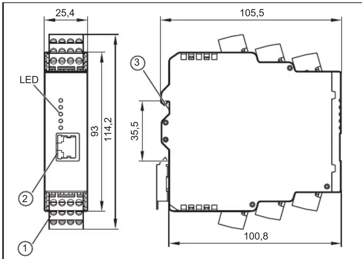
| Dimensions (L × H × D) | 25.4 × 114.2 × 105.5 mm |
| Weight | Approx. 200 g |
| Power supply | 24 V DC, max. 2 A (external protection) |
| Dynamic inputs | 4 inputs for vibration sensors (IEPE or IFM VSA/VSP) |
| Analog inputs | 2 inputs for current signals (0/4…20 mA) or pulses |
| Outputs | 2 digital outputs (NO/NC) or 1 analog output (0/4…20 mA) + 1 digital output |
| Interface | Ethernet RJ45, default IP address 192.168.0.1 |
| Main functions | Vibration monitoring, FFT analysis, trends, alarms, counter, OPC server |
| Configuration software | VES004 (downloadable from ifm.com) |
| LED indicators | 4 LEDs for sensors (green/yellow/red) + 1 system LED |
| Protection | IP20 (terminals), installation required in IP54 enclosure |
| Maintenance | No maintenance required in normal operation |
| Repairability | Repair only by the manufacturer |
| Spare parts | Plug-in terminal blocks (E40171, E40173), Ethernet cables (EC2080, E30112) |
| Standards | CE, TBTS, protection class II (EN61010) |
Frequently Asked Questions - VSE002 IFM
User questions about VSE002 IFM
0 question about this device. Answer the ones you know or ask your own.
Ask a new question about this device
Download the instructions for your Vibration sensor in PDF format for free! Find your manual VSE002 - IFM and take your electronic device back in hand. On this page are published all the documents necessary for the use of your device. VSE002 by IFM.
USER MANUAL VSE002 IFM
natural_image
Abstract geometric logo with stylized white lines and a circular background (no text or symbols)CE
Bedienungsanleitung
Diagnoseelektronik
Operating instructions
Diagnostic electronics
for vibration sensors
natural_image
Pure architectural floor plan outline without any text, numbers, or symbolsInhalt
5.1 Limited voltage / current
1 Preliminary note ....3
2 Safety instructions ....3
3 Functions and features ....3
4 Installation....5
4.1 Installation of the sensors ....5
5 Electrical connection ....5
5.1 Limited voltage / current 6
5.2 Wiring....6
5.2.1 Wiring of the sensors 1...4 (S1...S4) according to the sensor .....7
5.3 Connection of the sensors ....8
5.3.1 Monitoring the sensor cable ....8
5.4 Ethernet connection ....8
5.5 IP address 8
6 Operation....8
6.1 Settings 9
7 Indicators (LEDs) ....10
8 Maintenance, repair and disposal 11
9 Scale drawing 11
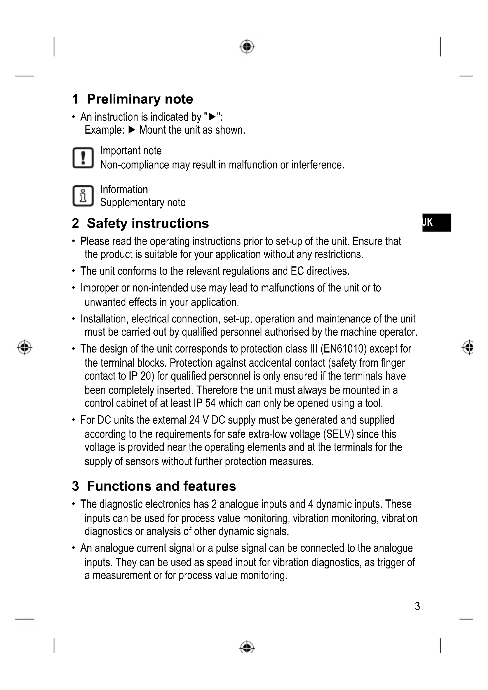
1 Preliminary note
- An instruction is indicated by "▶": Example: ▶ Mount the unit as shown.

Important note
Non-compliance may result in malfunction or interference.

Information
Supplementary note
2 Safety instructions
- Please read the operating instructions prior to set-up of the unit. Ensure that the product is suitable for your application without any restrictions.
- The unit conforms to the relevant regulations and EC directives.
- Improper or non-intended use may lead to malfunctions of the unit or to unwanted effects in your application.
- Installation, electrical connection, set-up, operation and maintenance of the unit must be carried out by qualified personnel authorised by the machine operator.
- The design of the unit corresponds to protection class III (EN61010) except for the terminal blocks. Protection against accidental contact (safety from finger contact to IP 20) for qualified personnel is only ensured if the terminals have been completely inserted. Therefore the unit must always be mounted in a control cabinet of at least IP 54 which can only be opened using a tool.
- For DC units the external 24 V DC supply must be generated and supplied according to the requirements for safe extra-low voltage (SELV) since this voltage is provided near the operating elements and at the terminals for the supply of sensors without further protection measures.
3 Functions and features
- The diagnostic electronics has 2 analogue inputs and 4 dynamic inputs. These inputs can be used for process value monitoring, vibration monitoring, vibration diagnostics or analysis of other dynamic signals.
- An analogue current signal or a pulse signal can be connected to the analogue inputs. They can be used as speed input for vibration diagnostics, as trigger of a measurement or for process value monitoring.

- An analogue current signal can also be connected to the dynamic inputs to monitor max. 4 more process values.
As an alternative, up to 4 vibration sensors from ifm (types VSA, VSP) or sensors with an IEPE standard signal can be connected.
- The possibilities of signal monitoring and signal analysis depend on the respective firmware version. The current firmware and operating software can be downloaded from the download area on ifm's website.
- The alarm states of the monitoring tasks (process values and/or objects) are indicated in the diagnostic electronic and/or the 2 hardware outputs via the LED of the respective sensor.
The hardware outputs can be configured as 2 x binary (NO/NC) or as 1 x analogue (0/4...20 mA) and 1x binary (NO/NC).
Examples of the firmware functions are:
- Online monitoring
- of process values (analogue signals) for current value above and/or below the limit value.
- of up to 24 indicators (objects) of the dynamic signals (e.g. vibration) in the time range or frequency range (FFT and/or H-FFT).
Monitoring of the objects is possible with regard to up to 2 process categories (e.g. load and rotational speed).
- Internal trend memory with RTC time stamp with flexible storage intervals for each object.
- Counter function
For monitoring and evaluation of the dynamic signals (e.g. vibration) the firmware provides the following tools or settings:
- Spectral analysis FFT, envelope-curve FFT, trend analysis
- Velocity monitoring to ISO 10816 with variable filter setting
All parameters are set and/or the monitoring tasks configured (process values and/or objects) via the PC software, article number VES004.
Via the Ethernet interface of the diagnostic electronics networking is possible to visualise data (measured values, alarm states, ...) in other systems (e.g. SCADA, MES, ....). The type VOS OPC server from ifm is a suitable optional accessing.

The device is not approved for safety-related tasks in the field of operator protection.
4 Installation
Mount the unit in a control cabinet with a protection rating of at least IP 54 to ensure protection against accidental contact with dangerous contact voltages and against atmospheric influence. The control cabinet should be installed in accordance with local and national rules and regulations.
Mount the unit on a DIN rail. Mount it vertically and leave enough space between the unit and the top and bottom of the control cabinet (to enable air circulation to avoid excessive heating).
At maximum ambient temperature, additional convection cooling is necessary. Prevent the penetration of conductive or other dirt during installation and wiring.
4.1 Installation of the sensors
▶ Adhere to the SELV criteria when the sensors are connected so that no dangerous contact voltages are applied to the sensor or transferred to the device!
Sensor and diagnostic electronics supply are not electrically isolated.
5 Electrical connection

The unit must be connected by a qualified electrician.
The national and international regulations for the installation of electrical equipment must be adhered to.
Avoid contact with dangerous contact voltages.
Disconnect power before connecting the unit! Check if the inputs and outputs are connected to voltages of external power supplies.
▶ Disconnect power
▶ Connect the unit
▶ To prevent negative effects on the functions caused by noise voltages, lay sensor cables and load cables separately. Maximum length of the sensor cable: 250 m.
Connection via Combicon connector (premounted).
The Combicon connectors are also available as accessories:
- connector with cage clamps, order no. E40171
- connector with screw terminals, order no. E40173
The outputs are short-circuit proof up to 100 mA. The outputs can be configured as either normally closed or normally open.
In addition an analogue signal can be provided on output [OU 1] (0/4...20 mA) (e.g. acceleration values).
5.1 Limited voltage / current
According to UL508 the device shall be supplied from an isolating source having a secondary UL-listed fuse rated
a) max 5 A for voltages 0...20 Vrms (0...28.3 Vp) or
b) 100/Vp for voltages of 20...30 Vrms (28.3...42.4 Vp).
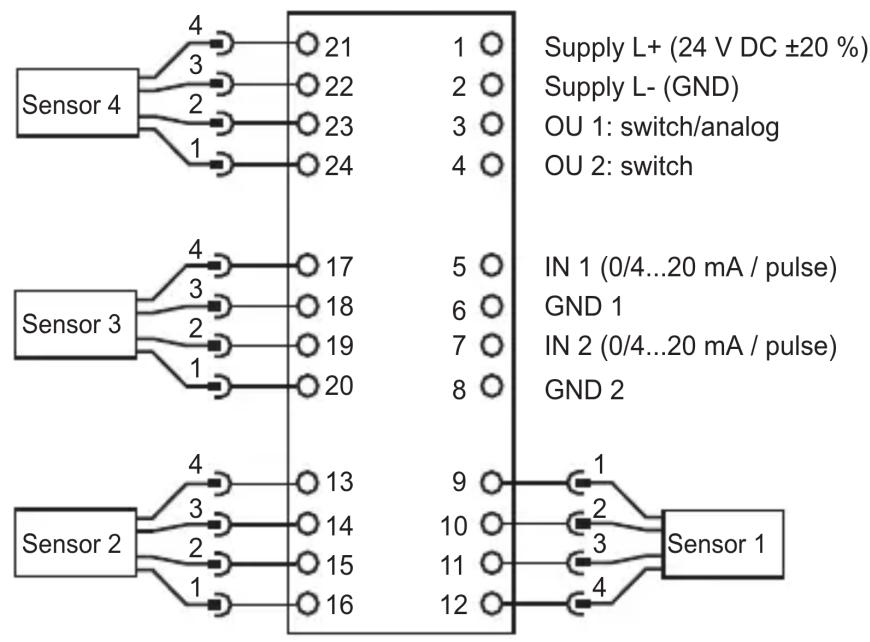
5.2 Wiring
flowchart
graph TD
    A["Sensor 4"] -->|4| B["21"]
    A -->|3| C["22"]
    A -->|2| D["23"]
    A -->|1| E["24"]
    F["Sensor 3"] -->|4| G["17"]
    F -->|3| H["18"]
    F -->|2| I["19"]
    F -->|1| J["20"]
    K["Sensor 2"] -->|4| L["13"]
    K -->|3| M["14"]
    K -->|2| N["15"]
    K -->|1| O["16"]
    P["Sensor 1"] -->|9| Q["1"]
    P -->|10| R["2"]
    P -->|11| S["3"]
    P -->|12| T["4"]
| Terminal Connection Description | ||
| 1 L+ 24 V DC supply | ||
| 2 L- GND | ||
| 3 OU 1 Early warning output | ||
| 4 OU 2 Main alarm output | ||
| 5 IN 1 Process value input 1 | ||
| 6 GND1 | ||
| 7 IN 2 Process value input 2 | ||
| 8 GND 2 | ||
UK
5.2.1 Wiring of the sensors 1...4 (S1...S4) according to the sensor
| Sensor input Usage | |||||||
| S1 S2 S3 | S4 VS | A VSP | IEPE 0...20 mA | ||||
| 9 | 16 | 20 | 24 | BN Sensor supply | Do not use | Do not use | Do not use |
| 10 | 15 | 19 | 23 | WHCurrent input0...10 mA | IEPE + | IEPE + | Current input0...20 mA |
| 11 | 14 | 18 | 22 | BU GND | IEPE - | IEPE - | GND |
| 12 | 13 | 17 | 21 | BKSelf-test output | Do not use | Do not use | Do not use |
▶ Protect the supply voltage externally (max. 2 A).

The ground GND of the DC supply is directly connected with the ground GND of the sensor supply. The SELV criteria must therefore be met for the DC supply (safety extra-low voltage, circuit electrically isolated from other circuits, not grounded).
If the DC circuit is to be grounded (e.g. due to national regulations), the PELV criteria must be adhered to (safety extra-low voltage, circuit electrically isolated from other circuits).
5.3 Connection of the sensors
▶ Adhere to the SELV criteria when the sensors are connected so that no dangerous contact voltages are applied to the sensor or transferred to the device!
Sensor and diagnostic electronics supply are not electrically isolated.
5.3.1 Monitoring the sensor cable
In case of wire break, short circuit or faulty measuring cell:
- the output [OU 1] provides 22 mA (± 2%) analogue or
• the output [OU 2] clocks at 1 Hz - the [SENS] LED flashes green
5.4 Ethernet connection
The RJ45 socket is used for the connection to the Ethernet.
Ethernet cables can be supplied as accessories, e.g.:
cross-over cable, 2 m, article no. EC2080
cross-over cable, 5 m, article no. E30112
5.5 IP address
The default IP address is 192.168.0.1.
6 Operation
The input signals are continuously detected and permanently monitored according to the set tasks (parameters). The monitoring tasks of the process values and objects (e.g. vibration monitoring and diagnostics) are defined on the PC by means of software (article number VES004) and then transferred to the diagnostic electronics as parameter set via Ethernet interface. The characteristic values (objects) in the frequency range are monitored in sequence (multiplex mode) while the time range is monitored simultaneously.
Alarm states of the set objects can be displayed on up to 2 digital outputs. Output 1 (OU 1) can also be used as analogue output (e.g. for transferring the total vibrations to ISO 10816). Alarm states of objects that are assigned to one of the 4 dynamic inputs (sensor 1...4) are displayed by the respective LEDs of the diagnostic electronics.
The operating state of the electronics and the sensors is also displayed via the multi-colour LEDs on the device.
6.1 Settings
The diagnostic electronics and the visualisation of online data (time signal, frequency spectra, object value, history data, ...) are configured via the software for the diagnostic electronics (article number VES004). An exact description of the functions and parameters can be found in the user manual or in the online help of the software.
UK


7 Indicators (LEDs)
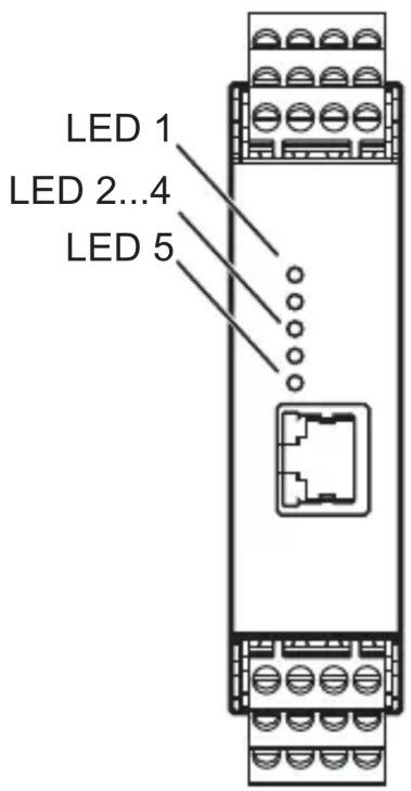
| LED 1 for sensor 1 | |
| Lights green Sensor connected and configured | |
| Flashes green Sensor is configured; type VSA sensor is not connected or faulty type IEPE sensor not connected | |
| Lights yellow Early warning | |
| Lights red Main alarm | |
| Flashes green/yellow alternately | Teach process active |
| Flashes yellow/red alternately | No parameter set loaded |
| LED 2 ditto for sensor 2 / LED 3 ditto for sensor 3 / LED 4 ditto for sensor 4 | |
| LED 5 for system | |
| Lights green System OK, monitoring running | |
| Lights yellow System OK, no monitoring due to parameter setting, self-test or FFT mode | |
| Flashes green/yellow alternately | Monitoring not possible, faulty parameter set |
| Flashes green/red alternately | System error, EEPROM faulty, other states error in the system, device function restricted |
8 Maintenance, repair and disposal
If used correctly, no maintenance and repair measures are necessary. Only the manufacturer is allowed to repair the unit. Dispose of the unit, including the battery, in an environmentally friendly way in accordance with the applicable national regulations when it is no longer used.
9 Scale drawing
UK
1: COMBICON plug
2: Ethernet interface
3: DIN rail adapter
Technical data and further information at www.ifm.com.
Contenu
5.1 Limited voltage / current
- Inhalt
- Limited voltage / current
- Preliminary note
- Safety instructions
- Functions and features
- Installation
- Installation of the sensors
- Electrical connection
- Wiring
- Wiring of the sensors 1...4 (S1...S4) according to the sensor
- Connection of the sensors
- Monitoring the sensor cable
- Ethernet connection
- IP address
- Operation
- Settings
- Indicators (LEDs)
- Maintenance, repair and disposal
- Scale drawing
- Contenu
Brand : IFM
Model : VSE002
Category : Vibration sensor