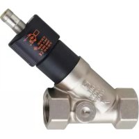
SBY433 - Flow sensor IFM - Free user manual and instructions
Find the device manual for free SBY433 IFM in PDF.


User questions about SBY433 IFM
0 question about this device. Answer the ones you know or ask your own.
Ask a new question about this device
Download the instructions for your Flow sensor in PDF format for free! Find your manual SBY433 - IFM and take your electronic device back in hand. On this page are published all the documents necessary for the use of your device. SBY433 by IFM.
USER MANUAL SBY433 IFM
Operating instructions
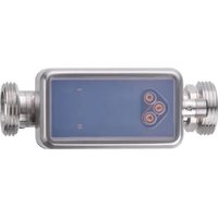
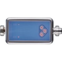
Mechatronic flow sensor
SBx4xx
Contents
1 Preliminary note.... 3
1.1 Symbols used.... 3
1.2 Warnings.... 3
2 Safety instructions 4
3 Transport, handling and storage 5
4 Intended use 6
4.1 Application area 6
5 Function 7
5.1 Analogue output.... 7
6 Mounting 8
6.1 Process connection.... 8
6.2 Interference.... 8
6.3 Mounting accessories 9
6.4 Installation in case of water containing dirt 9
7 Electrical connection 10
8 Troubleshooting.... 11
9 Maintenance, repair and disposal 12
9.1 Clean the device 12
1 Preliminary note
You will find instructions, technical data, approvals and further information using the QR code on the unit / packaging or at documentation.ifm.com.
1.1 Symbols used
Requirement
Instruction
Reaction, result
bold Designation of keys, buttons or indications
→ Cross-reference without link
→ Cross-reference with link


1.2 Warnings
Warnings indicate the possibility of personal injury and damage to property. This enables safe product handling. Warnings are graded as follows:

WARNING
Warning of serious personal injury
▷ If the warning is not observed, fatal and serious injuries are possible.

CAUTION
Warning of minor to moderate personal injury
▷ If the warning is not observed, minor to moderate injuries are possible.

ATTENTION
Warning of damage to property
▷ If the warning is not observed, damage to property is possible.
2 Safety instructions
- The unit described is a subcomponent for integration into a system.
- The system architect is responsible for the safety of the system.
-
The system architect undertakes to perform a risk assessment and to create documentation in accordance with legal and normative requirements to be provided to the operator and user of the system. This documentation must contain all necessary information and safety instructions for the operator, the user and, if applicable, for any service personnel authorised by the architect of the system.
-
Read this document before setting up the product and keep it during the entire service life.
- The product must be suitable for the corresponding applications and environmental conditions without any restrictions.
- Only use the product for its intended purpose (→ Intended use).
- Only use the product for permissible media.
- If the operating instructions or the technical data are not adhered to, personal injury and/or damage to property may occur.
- The manufacturer assumes no liability or warranty for any consequences caused by tampering with the product or incorrect use by the operator.
- Installation, electrical connection, set-up, operation and maintenance of the product must be carried out by qualified personnel authorised by the machine operator.
- Protect units and cables against damage.
3 Transport, handling and storage
▶ Store the device in its original packaging.
▶ When the device is to be stored again, use the original packaging.
▶ Otherwise, provide unused connections with either a mating connector or a protective cap and pack the device in suitable packaging.
▶ Observe the permissible ambient conditions for the device during storage (→ Technical data).
4 Intended use
The unit monitors liquid media.
The device detects the volume flow (flow rate/time) and outputs an analogue signal that is proportional to the process value.
4.1 Application area
- Water
- Glycol solutions
- Industrial oils
- Cooling lubricants

ATTENTION
Frost formation of the medium.
▷ The sensor may be damaged.
▶ Ensure that the medium in the sensor does not freeze during operation and transport.
5 Function
The unit detects the flow according to the principle of differential pressure by means of a permanent magnet and a measuring cell.
5.1 Analogue output
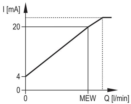
Fig. 1: Analogue output (water 20 °C)
The analogue signal for water is linear from 4 mA (= no flow) to 20 mA (= final value of the measuring range, VMR).
If the measured value is above the final value of the measuring range, a current signal of > 20 mA is output.
6 Mounting

CAUTION
During installation or in case of a fault (e.g. housing damage) media under high pressure or hot media can leak from the system.
▷ Risk of injury caused by pressure or burns.
▶ Ensure that the system is free of pressure during installation.
▶ Ensure that no media can leak at the mounting location during installation.
▶ Equip the unit with suitable protection (e.g. cover) to avoid hazard to personnel from leaking media.
6.1 Process connection
▶ Avoid major changes of cross section on the inlet side.
▶ Fit the unit in the pipe in accordance with the flow direction (arrow) and tighten at the spanner flats.

Do not clamp the housing in a vice.

Fig. 2: Process connection
IN: Inlet
OUT: Outlet

Loosening the socket head screw (1) and moving the cap do not change the setting of the sensor. However, moving the cap may be useful to read the label.

Calming sections on the sensor's inlet or outlet side are not necessary.

The sensor can also prevent backflow.
6.2 Interference
▶ The following minimum distances must be adhered to:
| Distance between the sensor and ferromagnetic materials | ≥ 30 mm * |
| Distance between the sensor and constant / alternating fields | ≥ 500 mm |
| Distance between the sensor axes for side-by-side installation | ≥ 50 mm |
* The pipe may consist of ferromagnetic material.
6.3 Mounting accessories
▶ If necessary, fasten the device on a mounting plate (not supplied) from underneath:

Fig. 3: Installation with mounting plate
1: Threaded hole M8 (depth 6 mm) on the bottom side of the unit
6.4 Installation in case of water containing dirt
▶ Use a 200-micron filter in front of the inlet (IN).
▶ Install sensor horizontally.
▶ Adhere to the inclination angle to the horizontal axis:
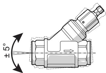

Fig. 4: Alignment in case of water containing dirt

In clean medium, installation in vertical pipes is also possible.
7 Electrical connection

The unit must be connected by a qualified electrician.
Observe the national and international regulations for the installation of electrical equipment.
Voltage supply according to SELV, PELV.
▶ Disconnect power.
▶ Connect the unit as follows:

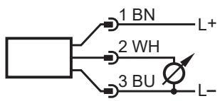
Fig. 5: Wiring diagram (colours to DIN EN 60947-5-2)
BN: Brown
BU: Blue
WH: White

Information on available sockets see: www.ifm.com.
8 Troubleshooting
If there are dirt particles between the float and the housing the display value of the sensor does not return to zero in case of flow standstill. In case of contamination the display value can be up to 30 % of the final value of the measuring range.
▶ Clean the device.
9 Maintenance, repair and disposal
The operation of the unit is maintenance-free.
Only the manufacturer is allowed to repair the unit.
▶ After use dispose of the device in an environmentally friendly way in accordance with the applicable national regulations.
9.1 Clean the device
If measurement errors occur because of an insufficient filtration cleaning may be required:
▶ Loosen socket head screw in the protective cover and unscrew.
▶ Unscrew sensor head.
▶ Remove float and spring.
▶ Clean the inside of the float, spring and housing, e.g. by means of compressed air.
▶ Before re-assembly check O-ring for damage. If necessary, replace and grease.
▶ After cleaning install components again.
▶ Tighten sensor head with a tightening torque of 10 Nm.
▶ To restore the measurement accuracy, press the float until you feel a mechanical stop using something non-magnetic, e.g. a finger and hold for at least 2 seconds.
▶ Screw and align protective cover and tighten socket head screw with a tightening torque of 0.7 Nm.
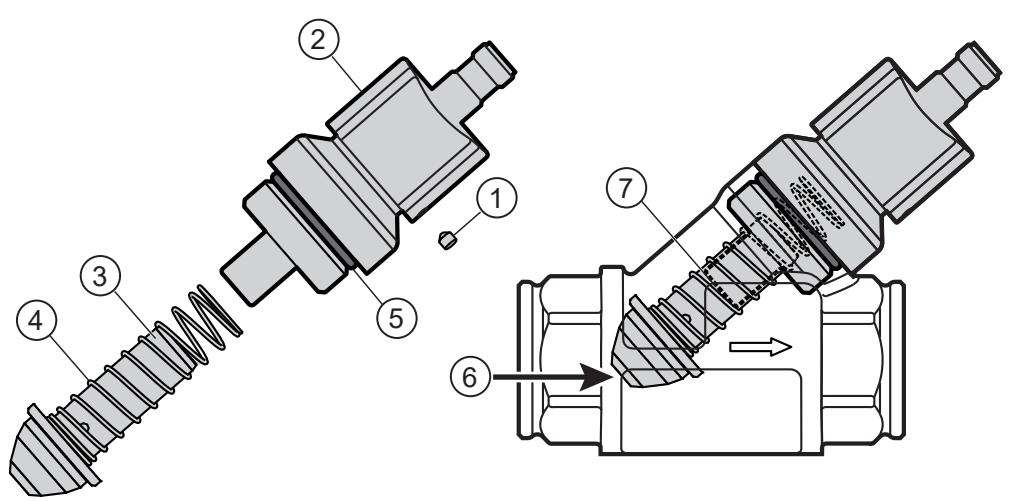
Fig. 6: Cleaning the sensor
1: Socket head screw
3: Float
5: O-ring:
7: Mechanical stop
2: Protective cover
4: Spring
6: Non-magnetic tool
- 1 PRELIMINARY NOTE
- 1.1 SYMBOLS USED
- 1.2 WARNINGS
- 2 SAFETY INSTRUCTIONS
- 3 TRANSPORT, HANDLING AND STORAGE
- 4 INTENDED USE
- 4.1 APPLICATION AREA
- 5 FUNCTION
- 5.1 ANALOGUE OUTPUT
- 6 MOUNTING
- 6.1 PROCESS CONNECTION
- 6.2 INTERFERENCE
- 6.3 MOUNTING ACCESSORIES
- 6.4 INSTALLATION IN CASE OF WATER CONTAINING DIRT
- 7 ELECTRICAL CONNECTION
- 8 TROUBLESHOOTING
- 9 MAINTENANCE, REPAIR AND DISPOSAL
- 9.1 CLEAN THE DEVICE
Brand : IFM
Model : SBY433
Category : Flow sensor