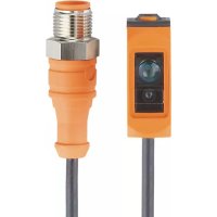
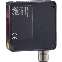
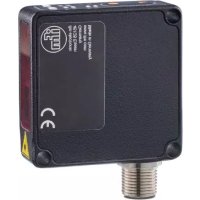
O6H707 - Photoelectric sensor IFM - Free user manual and instructions
Find the device manual for free O6H707 IFM in PDF.


User questions about O6H707 IFM
0 question about this device. Answer the ones you know or ask your own.
Ask a new question about this device
Download the instructions for your Photoelectric sensor in PDF format for free! Find your manual O6H707 - IFM and take your electronic device back in hand. On this page are published all the documents necessary for the use of your device. O6H707 by IFM.
USER MANUAL O6H707 IFM
Operating instructions
Diffuse reflection sensor with background suppression
O6H7
Contents
1 Preliminary note 3
1.1 Symbols used 3
1.2 Warnings.... 3
2 Safety instructions.... 4
3 Intended use.... 5
4 Installation.... 6
5 Operating and display elements 7
5.1 Stability indication 7
6 Electrical connection.... 8
6.1 PNP 8
6.2 NPN 8
7 Settings....9
7.1 Set via the sensor 9
7.1.1 Sensor is to switch when the object is detected 9
7.1.2 Sensor is not to switch when the object is detected 9
7.1.3 Set maximum range 9
7.1.4 Programming unsuccessful....9
7.1.5 Electronic lock.... 10
7.2 Set via IO-Link 10
7.2.1 General information.... 10
7.2.2 Device-specific information 10
7.2.3 Parameter setting tools 10
7.2.4 Functions 10
7.2.5 Adjustable parameters 10
7.2.6 Set range by means of background and object 11
7.2.7 Set range by means of background.... 12
7.2.8 Read distance value 12
7.2.9 Set maximum range 12
8 Operation 13
9 Maintenance, repair and disposal 14
1 Preliminary note
You will find instructions, technical data, approvals and further information using the QR code on the unit / packaging or at documentation.ifm.com.
1.1 Symbols used
√ Requirement
Instructions
Reaction, result
[...] Designation of keys, buttons or indications
→ Cross-reference

Important note
Non-compliance may result in malfunction or interference.

Information
Supplementary note
1.2 Warnings
Warnings indicate the possibility of personal injury and damage to property. This enables safe product handling. Warnings are graded as follows:

WARNING
Warning of serious personal injury
▷ If the warning is not observed, fatal and serious injuries are possible.

CAUTION
Warning of minor to moderate personal injury
▷ If the warning is not observed, minor to moderate injuries are possible.
ATTENTION
Warning of damage to property
▷ If the warning is not observed, damage to property is possible.
2 Safety instructions
- The unit described is a subcomponent for integration into a system.
- The system architect is responsible for the safety of the system.
-
The system architect undertakes to perform a risk assessment and to create documentation in accordance with legal and normative requirements to be provided to the operator and user of the system. This documentation must contain all necessary information and safety instructions for the operator, the user and, if applicable, for any service personnel authorised by the architect of the system.
-
Read this document before setting up the product and keep it during the entire service life.
- The product must be suitable for the corresponding applications and environmental conditions without any restrictions.
- Only use the product for its intended purpose ( → → Intended use).
- If the operating instructions or the technical data are not adhered to, personal injury and/or damage to property may occur.
- The manufacturer assumes no liability or warranty for any consequences caused by tampering with the product or incorrect use by the operator.
- Installation, electrical connection, set-up, operation and maintenance of the product must be carried out by qualified personnel authorised by the machine operator.
- Protect units and cables against damage.

CAUTION
Exposure to radiation
▷ Injury due to dangerous exposure to radiation
▶ Only use the operating and adjusting devices indicated in the operating instructions.

CAUTION
Visible laser light; LASER CLASS 1.
EN/IEC 60825-1 : 2007 and EN/IEC 60825-1 : 2014
Complies with 21 CFR 1040.10 except for conformance with IEC 60825-1 Ed. 3., as described in Laser Notice No. 56, dated May 8, 2019.
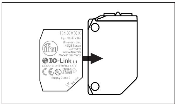
Position of the product label
Warning sign

3 Intended use
▷ The diffuse reflection sensor detects objects and materials without contact and indicates their presence by a switching signal.
4 Installation

▶ Align the diffuse reflection sensor to the object to be detected.
▶ Secure it to a bracket.
The objects to be detected should move transversely to the lens of the sensor.
▶ In case of other directions of movement it should be tested before whether safe switching is guaranteed.
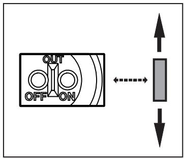
Object shiny
▶ In case of shiny object surfaces and less shiny background surfaces the sensor should be mounted at an angle of approx. 5 to 10° .
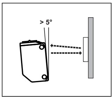
Background shiny
▶ In case of shiny background surfaces and less shiny object surfaces the sensor should be mounted vertically to the background surface.
5 Operating and display elements
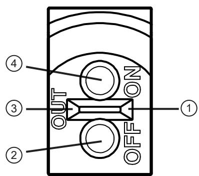
1: LED green - operation, stability indication
2: Button [OUT OFF]
3: LED yellow - switching output active
4: Button [OUT ON]
5.1 Stability indication
▷ The green LED is lit when the supply voltage is applied and there is sufficient excess gain. Under these conditions the sensor receives a stable signal.
| Stable signal | Switch point | Stable signal | ||
 | ||||
| Light-on mode | ||||
| LED green | on | off | off | on |
| LED yellow | on | on | off | off |
| Dark-on mode | ||||
| LED green | on | off | off | on |
| LED yellow | off | off | on | on |
6 Electrical connection

The unit must be connected by a qualified electrician.
Observe the national and international regulations for the installation of electrical equipment.
Voltage supply according to SELV, PELV.
▶ Disconnect power.
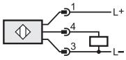
▶ Connect the unit as follows:
6.1 PNP
| M12 pigtail plug | Cable * | |
 |  |  |
| M8 connector, 3 poles | M8 connector, 4 poles | ||
 | 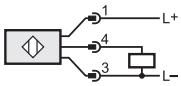 |  |  |
* Core colours: BN = brown, BU = blue, BK = black
6.2 NPN
| M12 pigtail plug | Cable * | |
 |  |  |
| M8 connector, 3 poles | M8 connector, 4 poles | ||
 | 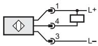 |  |  |
* Core colours: BN = brown, BU = blue, BK = black
7 Settings
7.1 Set via the sensor
7.1.1 Sensor is to switch when the object is detected

Fig. 1: Button [OUT ON]
▶ Position the object.
▶ Press [OUT ON] > 2 s.
▷ The yellow LED flashes.
▷ The setting of the range with object is made by releasing [OUT ON].

Fig. 2: Button [OUT OFF]
▶ Remove the object.
▶ Press [OUT OFF].
▷ The setting of the range without object is made by releasing [OUT OFF].
▷ The yellow LED goes out. Programming is completed.
7.1.2 Sensor is not to switch when the object is detected
▶ Position the object (see figure 1) and press [OUT OFF] > 2 s.
▶ Remove the object (see fig. 2) and press [OUT ON].

The settings can also be carried out first without object and then with object.
7.1.3 Set maximum range
▶ Align the sensor so that no light is reflected.
Sensor is to switch when the object is detected
▶ Press[OUT ON] > 2 s, then press [OUT OFF].
Sensor is not to switch when the object is detected
▶ Press[OUT OFF] > 2 s, then press [OUT ON].
7.1.4 Programming unsuccessful
Failed programming is signalled by the fast flashing LED (8 Hz).
Possible causes:
• Measured value difference too small
• Max. programming time (15 min.) exceeded.
7.1.5 Electronic lock
Lock or unlock the buttons
▶ Press [OUT ON] and [OUT OFF] simultaneously for 10 s.
▷ Acknowledgement is indicated by a brief change of the LED status.
7.2 Set via IO-Link
7.2.1 General information
This unit has an IO-Link communication interface that requires an IO-Link capable module (IO-Link master) for operation.
The IO-Link interface enables direct access to the sensor values and parameters and provides the possibility to set the parameters of the unit during operation.
In addition, communication is possible via a point-to-point connection with a USB adapter cable.
You will find more detailed information about IO-Link at www.ifm.com.
7.2.2 Device-specific information
You will find the IODDs required for the configuration of the IO-Link unit and detailed information about sensor values, diagnostic information and parameters in the overview table at www.ifm.com.
7.2.3 Parameter setting tools
You will find all necessary information about the required IO-Link hardware and software at www.ifm.com.
7.2.4 Functions
With IO-Link all functions and measured data are available that can also be accessed via the display and pushbuttons on the unit.
All functions are described in detail in the IODD.
7.2.5 Adjustable parameters
Among others, the following parameters can be set via IO-Link.
You will find the IODDs necessary for the configuration of the IO-Link unit and detailed information about sensor values, diagnostic information and parameters in the overview table at www.ifm.com.
| Parameter | Values | Description | Default setting |
| [SSC1 Param. SP1] | 17 mm ...100 mm | Setting of switch point in 1 mm increments. After a teach process the resulting value is displayed. | Please refer to the data sheet value "Range" |
| [Teach SP1 TP1] | Teach sequence to set switch point [SP1]. Part One [TP1]: teach on object. Both parts of the teach sequence for [TP1] and [TP2] have to be executed in order to place switch point [SP1] between the object and the background ([TP] = Teach point). | n.a. | |
| [Teach SP1 TP2] | Teach sequence to set switch point [SP1]. Second part [TP2]: teach on background. Both parts of the teach sequence for [TP1] and [TP2] have to be carried out ([TP] = Teach point). | n.a. | |
| [Teach Custom SP1 without target] | Teaching on the background only, the switch point is defined just before the background. Select this setting as alternative to teaching [SP1] if no object is available. | n.a. | |
| [TI Result. State] | · [Idle] · [SP1 Success] · [Wait for command] · [Busy] · [Error] · [Custom] | Teach-in status; after successful teach the value "[SP1 Success]" is displayed. | n.a. |
| [Sequence modulation] | · [OFF] · [AUTo] | [OFF]: anti-crosstalk function off [AUTo]: anti-crosstalk function on | [OFF] |
| [SSC1 Config. Logic] | [High active] [Low active] | Switch point logic, status for detected object (High: light-on mode / normally open, Low: dark-on mode / normally closed) | Please refer to the data sheet value [output function] |
| [SSC1 SwitchOn delay] | 0 ... 2 | Switch-on delay; step increment 0.1 s | 0 |
| [SSC1 Switch Off delay] | 0 ... 2 | Switch-off delay step increment 0.1 s | 0 |
| [ModE] | · [Switching] · [Measuring] | [Switching]: Mode for switching signals [Measuring]: Mode for distances | n.a. |
| [Transmitter configuration] | · [On] · [Off] | Configuration transmitted light on / off | [On] |
| [Number of power cycles] | 0 ... 65535 | Number of switching operations (power up) of the sensor | n.a. |
| [Operating hours] | 0 ... 65535 | Operating hours | n.a. |
7.2.6 Set range by means of background and object
▶ Start the parameter setting software.
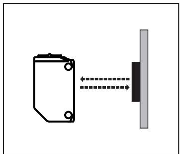
▶ Align the diffuse reflection sensor to the object (fig. 3).
▶ Click the button [Teach SP1 TP1] in the parameter setting software.
▶ Align the diffuse reflection sensor to the background (fig. 4).
▶ Click the button [Teach SP1 TP2] in the parameter setting software.
▷ The switch point [SP1] is between object and background (fig. 5).

Fig. 3: Sensor - object
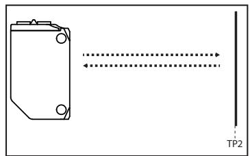
Fig. 4: Sensor - background
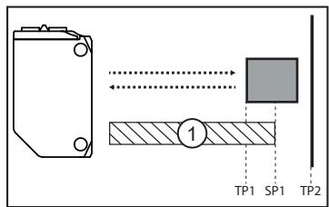
Fig. 5: Position switch point [SP1]
Either the object can be set first and then the background, or the other way around.
7.2.7 Set range by means of background
If the object is not available, the range can be set using only the background.
The switching characteristics of the diffuse reflection sensor are most reliable if the range is set using the background and the object. ( → Set range by means of background and object ☐ 11)
▶ Start the parameter setting software.
▶ Align the diffuse reflection sensor to the background (fig. 6).
▶ Click the button [Teach Custom - SP1 without target] in the parameter setting software.
▷ The switch point [SP1] is just in front of the background (fig. 7).

Fig. 6: Diffuse reflection sensor directed towards background
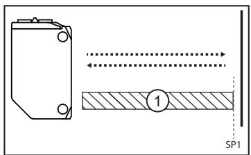
Fig. 7: Diffuse reflection sensor directed towards background with [SP1]
1: zone "object recognised"
7.2.8 Read distance value
Distance values can also be determined via the IO-Link function.
▶ Start the parameter setting software.
▶ Change parameter [ModE] from [Switching] to [Measuring].
▷ The sensor transmits distance values to the parameter setting software.
7.2.9 Set maximum range
▶ Start the parameter setting software.
▶ Align the diffuse reflection sensor to an empty area without object or background.
The diffuse reflection sensor must not receive any light from the object or the background.
▶ Click the button [Teach Custom - SP1 without target] in the parameter setting software.
8 Operation
▶ Check whether the unit operates correctly.
The green LED is lit when the supply voltage is applied and there is sufficient excess gain.
▷ Setting the dark-on mode: The output is switched / the yellow LED is on when an object is detected.
▷ Setting the light-on mode: The output is switched / the yellow LED is on when no object is detected.
9 Maintenance, repair and disposal
▶ Keep the lenses of the sensor free from soiling.
▶ For cleaning do not use any solvents or cleaning agents which could damage the plastic parts.
▶ After use dispose of the unit in an environmentally friendly way in accordance with the applicable national regulations.
Faulty sensors must only be repaired by the manufacturer.
- 1 PRELIMINARY NOTE
- 1.1 SYMBOLS USED
- 1.2 WARNINGS
- 2 SAFETY INSTRUCTIONS
- 3 INTENDED USE
- 4 INSTALLATION
- 5 OPERATING AND DISPLAY ELEMENTS
- 5.1 STABILITY INDICATION
- 6 ELECTRICAL CONNECTION
- 6.1 PNP
- 6.2 NPN
- 7 SETTINGS
- 7.1 SET VIA THE SENSOR
- 7.1.1 SENSOR IS TO SWITCH WHEN THE OBJECT IS DETECTED
- 7.1.2 SENSOR IS NOT TO SWITCH WHEN THE OBJECT IS DETECTED
- 7.1.3 SET MAXIMUM RANGE
- 7.1.4 PROGRAMMING UNSUCCESSFUL
- 7.1.5 ELECTRONIC LOCK
- 7.2 SET VIA IO-LINK
- 7.2.1 GENERAL INFORMATION
- 7.2.2 DEVICE-SPECIFIC INFORMATION
- 7.2.3 PARAMETER SETTING TOOLS
- 7.2.4 FUNCTIONS
- 7.2.5 ADJUSTABLE PARAMETERS
- 7.2.6 SET RANGE BY MEANS OF BACKGROUND AND OBJECT
- 7.2.7 SET RANGE BY MEANS OF BACKGROUND
- 7.2.8 READ DISTANCE VALUE
- 7.2.9 SET MAXIMUM RANGE
- 8 OPERATION
- 9 MAINTENANCE, REPAIR AND DISPOSAL
Brand : IFM
Model : O6H707
Category : Photoelectric sensor