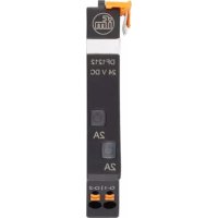
DF1212 - Circuit breakers IFM - Free user manual and instructions
Find the device manual for free DF1212 IFM in PDF.


User questions about DF1212 IFM
0 question about this device. Answer the ones you know or ask your own.
Ask a new question about this device
Download the instructions for your Circuit breakers in PDF format for free! Find your manual DF1212 - IFM and take your electronic device back in hand. On this page are published all the documents necessary for the use of your device. DF1212 by IFM.
USER MANUAL DF1212 IFM
Operating instructions
Electronic circuit breakers, standard for the 24 V DC secondary circuit
DF11xx
DF12xx
DF25xx
Contents
1 Preliminary note 3
1.1 Symbols used 3
2 Safety instructions.... 4
3 Intended use 5
4 Function 6
4.1 Temperature factor / continuous current rating 6
4.2 Fail-safe element 6
5 Installation.... 7
6 Electrical connection.... 8
6.1 Supply, feedback and potential modules.... 8
7 Operating and display elements 9
7.1 DF12xx circuit protection modules 9
7.2 Interrogation of module to confirm the set nominal current 9
7.3 Setting of the nominal current 10
8 Maintenance, repair and disposal 11
1 Preliminary note
You will find instructions, technical data, approvals and further information using the QR code on the unit / packaging or at www.ifm.com.
1.1 Symbols used
√ Requirement
Instructions
Reaction, result
[...] Designation of keys, buttons or indications
→ Cross-reference

Important note
Non-compliance may result in malfunction or interference.

Information
Supplementary note
2 Safety instructions
- The unit described is a subcomponent for integration into a system.
- The system architect is responsible for the safety of the system.
-
The system architect undertakes to perform a risk assessment and to create documentation in accordance with legal and normative requirements to be provided to the operator and user of the system. This documentation must contain all necessary information and safety instructions for the operator, the user and, if applicable, for any service personnel authorised by the architect of the system.
-
Read this document before setting up the product and keep it during the entire service life.
- The product must be suitable for the corresponding applications and environmental conditions without any restrictions.
- Only use the product for its intended purpose (→ Intended use).
- If the operating instructions or the technical data are not adhered to, personal injury and/or damage to property may occur.
- The manufacturer assumes no liability or warranty for any consequences caused by tampering with the product or incorrect use by the operator.
- Installation, electrical connection, set-up, operation and maintenance of the product must be carried out by qualified personnel authorised by the machine operator.
- Protect units and cables against damage.
- Replace damaged units, otherwise the technical data and safety will be impaired.
- The devices are intended for use with a 24 V DC safety extra-low voltage.
- A wrong connection to voltage which is higher and/or not safely isolated may lead to damage or conditions which are dangerous to life.
- Use the supply module only with the matching circuit protection modules.
- Do not mount the devices and do not actuate the contact levers while live.
- After triggering a circuit protection module and before power on again, remove the cause of triggering (short circuit or overload).
- Check the devices for damage prior to installation. Defective devices must not be used.
• Supply the devices with energy only after they have been properly installed.
3 Intended use
Electronic overcurrent protection for primary switched-mode 24V DC power supplies. A supply module must be combined with at least one circuit protection module and, optionally, complemented by supply/feedback/potential modules.
4 Function
The circuit protection modules are available with either fixed or adjustable currents and are equipped with a fail-safe element (integrated fuse).
| DF1100 | DF1208 | DF1210 | DF1212 | DF1214 | DF1216 | DF1220 | DF2520 | DF2524 | ||
| Supply module | ● | — | ||||||||
| Circuit protection module | — | ● | ||||||||
| Interface | — | — | IO-Link | |||||||
| Max. number of circuit protection modules per supply module | — | 10 | ||||||||
| Electrical data | ||||||||||
| Input voltage | [V] | 18...30 DC (SELV/PELV) | ||||||||
| Nominal voltage | [V] | 24 DC | ||||||||
| NEC Class 2 | — | — | ● | ● | — | — | — | ● | ||
| Input current (= max. total current) | [A] | 40 | — | |||||||
| Number of channels | — | 1 | 2 | |||||||
| Nominal current IN | [A] | 8 | 10 | 2 | 4 | 6 | 1...10 | 1...10 | ||
| Fail-safe IN | [A] | 8 | 10 | 2 | 4 | 6.3 | 16 | 16 | ||
| Mechanical data | ||||||||||
| Installation | rail TH35 (to EN 60715) | |||||||||
| Device width | [mm] | 12.5 | ||||||||
| Ambient temperature | [°C] | -25...60 | ||||||||
| Storage temperature | [°C] | -40...70 | ||||||||
| Protection rating → Installation | IP 30 (installation area)IP 20 (operating area) | |||||||||
| Electrical connection | ||||||||||
| Type | push-in terminals, contact lever/strip | |||||||||
| ● = applicable | ||||||||||
4.1 Temperature factor / continuous current rating
The time-current characteristic curve depends on the ambient temperature. To determine the max. permitted load current multiply the nominal device current by the temperature factor taking into consideration the series connection.
| Ambient temperature [°C] | 0 | 10 | 23 | 40 | 50 | 60 |
| Temperature factor | 1 | 1 | 1 | 0.95 | 0.90 | 0.85 |
With series installation the nominal device current can be max. 80% or has to be overdimensioned accordingly. With increased temperature the load current warning limit "warning limit typ. 0.8 × IN " is reduced by the temperature factor.
4.2 Fail-safe element
The load circuits are additionally protected by the circuit protection modules that are equipped with a fail-safe element (integrated fuse). The fail-safe element is adapted to the nominal current IN of the respective circuit protection module and the respective wire cross-sections.
5 Installation
▶ Mount the devices on a 35 mm rail.

Fig. 1: Example circuit protection module DF12xx
1: Rail
2: Contact lever
3: Installation area
4: Operating area
6 Electrical connection
▶ Dimension cables according to input and output current.
▶ Insert wires directly into the terminals as shown on the device label.
| Art. no. | Terminals | Potential | Cross-section [mm2] | Stripping length [mm] |
| DF11xx | 24 V DC | supply | 0.5...10 | 18 |
| 0 V | 0.14...2.5 | 8...10 | ||
| 13-14 | normally open | 0.14...2.5 | 8...10 | |
| DF12xx | O1 or O1/O2 | current outputs | 0.14...2.5 | 8...10 |

To disconnect press the orange pusher using a suitable tool.
To open the push-in terminals IO-Link use a 2 mm wide micro screwdriver.

As soon as the supply module is supplied with voltage, the device closes the contacts connected to terminals 13 and 14. If a fault occurs at one (or several) of the connected channels, the device opens the contacts again.
6.1 Supply, feedback and potential modules
In combination with GND potential modules (DF311x) the GND supply modules (DF310x) are used to reduce wiring.
In order to avoid that subsequent modules are disconnected from the voltage supply when opening a contact lever, a feedback module (DF3210) can be used to ensure that the respective modules are still supplied with power.
A LOAD potential module (DF320x) is used to extend +24 V DC circuit protection outputs to other connections.
7 Operating and display elements

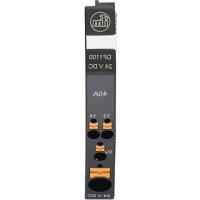
Fig. 2: Example DF11xx supply module
1: Panel for labelling
2: Push-in terminals switching output 13/14
3: Push-in terminal 0 V
4: Push-in terminal 24 V DC
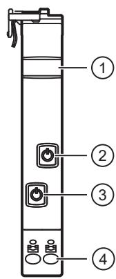
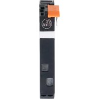
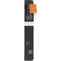
Fig. 3: Example DFx2xx circuit protection module
1: Panel for labelling
2: ON/OFF/reset button and status LED (channel 2)
3: ON/OFF/reset button and status LED (channel 1)
4: Push-in terminals outputs 1/2
7.1 DF12xx circuit protection modules
The different operating states of the circuit protection modules are indicated by the status LED.
| Status LED | Operating status | Status of load output | |
| — | off | Missing operating voltage, error in initialisation or channel switched off via button | off |
| green | on | Channel switched on, no fault | on |
| green/orange | flashing | Load current limit reached | on |
| orange | on | Overload or short circuit until disconnection | on |
| Channel switched off | off | ||
| red | on | Triggering via short circuit or overload | off |
| Undervoltage in ON status with automatic switching on again | |||
Tab. 1: Status LED DF12xx circuit protection modules
7.2 Interrogation of module to confirm the set nominal current
Only for circuit protection modules with adjustable nominal current.
▶ Press the ON/OFF/reset button of the requested channel between 2 and 5 seconds.
▷ The status LED of the selected channel flashes red once.
▷ The status LED flashes orange to display the set nominal current. The LED flashes red once to confirm completion of the cycle. The LED flashes orange, once or multiple times, in accordance with nominal current setting in amperes (orange flashing once = 1 A; orange flashing twice = 2 A; etc.).
▷ The set nominal current is displayed five times. After 5 cycles the display changes to the current operating status.
▶ To interrupt/stop the interrogation cycle, and return to normal status indication mode, press the ON/OFF/reset button of the requested channel at any time.
7.3 Setting of the nominal current
Only for circuit protection modules with adjustable nominal current.
▶ Press the ON/OFF/reset button of the requested channel min. 5 seconds.
▷ The status LED of the selected channel flashes red once.
▷ The status LED slowly flashes green, max. 10 times, then red once.
▶ Press the ON/OFF/reset button of this channel when the LED signals the requested nominal current value (after the first time flashing green = 1 A; after the second time flashing green = 2 A; etc.).
▷ The selected nominal current is set for this channel.
▷ Display changes to the current operating status.
8 Maintenance, repair and disposal
The operation of the unit is maintenance-free.
Only the manufacturer is allowed to repair the unit.
▶ After use dispose of the device in an environmentally friendly way in accordance with the applicable national regulations.
Cleaning the unit:
▶ Disconnect the unit from the voltage supply.
▶ Clean the unit from dirt using a soft, chemically untreated and dry micro-fibre cloth.
- 1 PRELIMINARY NOTE
- 1.1 SYMBOLS USED
- 2 SAFETY INSTRUCTIONS
- 3 INTENDED USE
- 4 FUNCTION
- 4.1 TEMPERATURE FACTOR / CONTINUOUS CURRENT RATING
- 4.2 FAIL-SAFE ELEMENT
- 5 INSTALLATION
- 6 ELECTRICAL CONNECTION
- 6.1 SUPPLY, FEEDBACK AND POTENTIAL MODULES
- 7 OPERATING AND DISPLAY ELEMENTS
- 7.1 DF12XX CIRCUIT PROTECTION MODULES
- 7.2 INTERROGATION OF MODULE TO CONFIRM THE SET NOMINAL CURRENT
- 7.3 SETTING OF THE NOMINAL CURRENT
- 8 MAINTENANCE, REPAIR AND DISPOSAL
Brand : IFM
Model : DF1212
Category : Circuit breakers