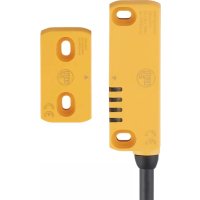
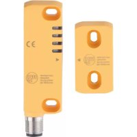
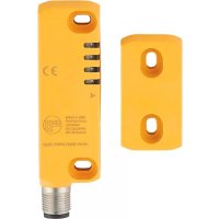
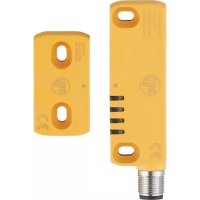
MN704S - Security detector IFM - Free user manual and instructions
Find the device manual for free MN704S IFM in PDF.


User questions about MN704S IFM
0 question about this device. Answer the ones you know or ask your own.
Ask a new question about this device
Download the instructions for your Security detector in PDF format for free! Find your manual MN704S - IFM and take your electronic device back in hand. On this page are published all the documents necessary for the use of your device. MN704S by IFM.
USER MANUAL MN704S IFM
CE
Original operating instructions
RFID-coded safety sensor
MN7xxS
UK

Contents
1 Preliminary note....3
1.1 Symbols used .... 3
1.2 Warning signs used .... 3
2 Safety instructions ....4
2.1 Safety-related requirements regarding the application....4
2.2 Radio equipment ....5
2.3 Interference of electronic and medical devices 6
3 Items supplied....6
4 Functions and features....6
5 Function....7
5.1 Limit range and operating range....7
6 Installation....8
6.1 Actuating directions ....8
7 Electrical connection....9
7.1 Series connection....10
8 Programming 11
9 Operation....12
9.1 Switching state of the outputs....12
9.1.1 The safe state....12
9.1.2 The switched state.... 12
9.1.3 Cross fault / short circuit 12
9.2 Interface classification 12
9.2.1 Identification key....12
9.3 Response times....13
9.4 LED display 14
9.4.1 5-wire design .... 14
9.4.2 8-wire design ....15
10 Technical data....16
11 Troubleshooting .... 18
12 Maintenance, repair and disposal....18
13 Approvals/standards 18
1 Preliminary note
The instructions are part of the unit. They are intended for authorised persons according to the EMC, Low Voltage and Machinery Directive and safety regulations. The instructions contain information about the correct handling of the product.
Read the instructions before use to familiarise yourself with operating conditions, installation and operation.
Follow the safety instructions.
1.1 Symbols used
Instructions
▷ Reaction, result
→ Cross-reference
Important note
Non-compliance may result in malfunction or interference.
Information
Supplementary note.
LED lights green
LED lights red
LED lights orange
LED lights green, red or orange
LED flashes
☐ LED off
1.2 Warning signs used
! WARNING
Warning of serious personal injury.
Death or serious irreversible injuries may result.
2 Safety instructions
- Follow the operating instructions.
- Improper use may result in malfunctions of the unit. This can lead to personal injury and/or damage to property during operation of the machine. For this reason note all remarks on installation and handling given in this document. Also adhere to the safety instructions for the operation of the whole installation.
- In case of non-observance of notes or standards, especially when tampering with and/or modifying the unit, any liability and warranty is excluded.
- If the sensor is damaged, the safety function cannot be guaranteed.
- Errors caused by damage cannot be detected by the sensor.
- The unit must be installed, connected and put into operation by a qualified electrician trained in safety technology.
- The applicable technical standards for the corresponding application must be complied with.
- For installation the requirements according to EN 60204 must be observed.
- In case of malfunction of the unit please contact the manufacturer. Tampering with the unit is not allowed.
- Disconnect the unit externally before handling it. Also disconnect any independently supplied relay load circuits.
- After installation, maintenance or repair of the system perform a complete function check.
- Only use the unit under the specified operating conditions ( → 10 Technical data). In case of special operating conditions please contact the manufacturer.
• Use only as described below ( → 4).
2.1 Safety-related requirements regarding the application
It must be ensured that the safety requirements of the respective application correspond to the requirements stated in these instructions.
! WARNING
Failure of the safety function
When used outside of the defined environmental conditions, the safety-related function of the sensor cannot be guaranteed.
▶ Use only in accordance with the defined environmental conditions ( → 10 Technical data).
Use of the sensor in the vicinity of chemical and biological media (solid, liquid, gaseous) as well as ionising radiation is not permitted.
Observe the following requirements:
▶ Only use cable glands, insulation material and connection wires that have an appropriate protection rating.
▶ Adhere to ISO 14119 for interlocking devices associated with guards.
▶ Adhere to the principle of normally closed operation for all external safety circuits connected to the system.
▶ The device must not be installed or operated in the environment of strong magnetic fields.
▶ Do not use the device as an end stop.
▶ In case of faults within the sensor which result in the defined safe state: Take measures to maintain the safe state when the complete control system continues to be operated.
▶ Sensors and actuators must be protected from strong shocks and vibrations. Observe the permissible environmental conditions ( → 10 Technical data).
▶ Annual function test ( → 12 Maintenance, repair and disposal).
▶ Replace damaged units.
2.2 Radio equipment
In general, the device must not be used in the vicinity of petrol stations, fuel de-pots, chemical plants or blasting operations.
▶ Do not transport and store any flammable gases, liquids or explosive substances near the unit.
2.3 Interference of electronic and medical devices
Operation of the unit can affect the function of electronic devices that are not correctly shielded.
▶ Disconnect the device in the vicinity of medical equipment.
▶ Contact the manufacturer of the corresponding device in case of any interference.
3 Items supplied
1 RFID-coded safety sensor, 1 RFID-coded actuator,
4 washers, 8 cover caps,
1 x original operating instructions, ident number 11559921.
If one of the above-mentioned components is missing or damaged, please contact one of the ifm branch offices.
4 Functions and features
RFID-coded safety sensors detect the corresponding actuators (ID-tags) without contact.
Coding levels according to EN ISO 14119:
| Sensor type | Performance | Coding level |
| Coded | Each sensor recognises each actuator of this type. | low |
| Codable | The sensor can be programmed for a specific actuator. | low |
| Unique coding | The sensor only detects the actuator with the corresponding coding. | high |
Safety-related function SF: The safe state (output stage switched off; Logic "0") is achieved if the distance to the actuator is greater than or equal to the safe switch off distance sar ( → 10 Technical data).
▶ Observe the notes on installation ( → 6 Installation).
The RFID-coded safety sensor has been certified by TÜVSüd.
5 Function

① LED
② Operating area
③ Switch-on distance sn (= 12 mm)
④ Limit range
⑤ Safe switch-off distance sar (= 16 mm)
5.1 Limit range and operating range
LED states when aligning the sensor with the actuator
| Status | Description | LED | ||||
| PWR | OUT | IN*) | ACT | |||
 | Actuator outside the limit area 4 Nominal voltage connected> Inputs active▷ Outputs deactivated | |||||
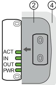 | Actuator within the actuating area 2▷ Outputs activated | |||||
 | Actuator leaves actuating area 2 and is in the limit area 4> Outputs remain active | |||||
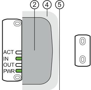 | The distance of the actuator to the sensor is larger than or equal to sar 5▷ Outputs deactivated | |||||
*) LED [IN] is not on in case of MN700S and MN703S.
6 Installation
6.1 Actuating directions
The sensor recognises the actuator from three different directions ②.
▶ When mounting the device, align the central marks ① of the sensor and the actuator in parallel to each other.
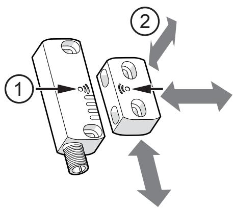
① Reference marks (central mark)
② Actuating direction

The actuator must not touch the sensor during operation. Do not use as an end stop.
- Do not adjust the device using mechanical force.
- Only mount on a flat surface to avoid damage or changes of the sensing range.

When using several sensors, a minimum distance of 50 mm in each direction must be maintained.
▶ Fasten the sensor and the actuator with two screws each (M4, > 18 mm) (tightening torque 0.8...2 Nm).

Using less than two screws for each component is not permissible. According to EN ISO 14119, the actuator must be fixed immovably.
Safety screws with one-way heads, rivets or the like are to be used.
After mounting, insert the supplied cover caps to make it more difficult to access screws or rivets.
7 Electrical connection

In case of a single fault, the supply voltage must not exceed a maximum of 60 V DC. (This requires the safe separation between power supply and transformer SELV / PELV.)
▶ Disconnect power. Also disconnect any independently supplied relay load circuits.
| Cable | Connector | |
| BK: black RD: redBN: brown VT: violetBU: blue WH: white | 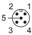 |  |
 PVC cable, 6 x 0.5 mm2 PVC cable, 6 x 0.5 mm2 |  M12 connector, 5-pole M12 connector, 5-pole | |
 PVC cable, 8 x 0.34 mm2 PVC cable, 8 x 0.34 mm2 |  M12 connector, 8-pole M12 connector, 8-pole | |
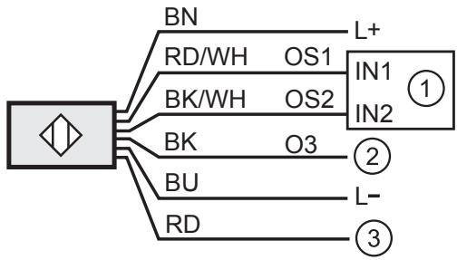
① Safety-related logic unit
② Programmable Logic Controller (PLC)
③ Programming input (MN702S, MN705S)

When connected directly to a controller both IN1 and IN2 must be connected.
The maximum permitted cable length is 50 m.
7.1 Series connection
General
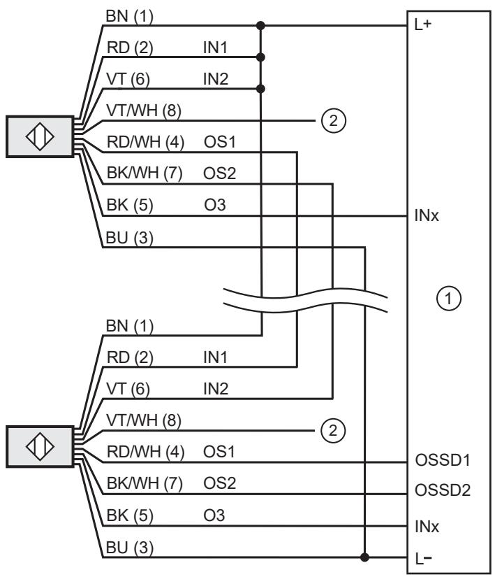
G150xS

① external controller
② programming input for codable sensors
8 Programming
The programmable version of the sensor is provided with a special programming input (IN3) that recognises the stored code in a new actuator.
The programming can be repeated as often as you like. ▶ After successful programming, the sensor will only recognise the code of the most recently programmed actuator.

The sensor may only be programmed by qualified staff.
| LED | Status | Description | |||
| PWR | OUT | IN | ACT | ||
| Switch-on operation | ▶ Connect the sensor to the nominal voltage. ▷ The device executes internal tests. | ||||
| Operation | Waiting for the input signal. | ||||
| Operation | Input signals available. ▷ Waiting for actuator. | ||||
| Programming | ▶ Activate the programming input IN3 by connecting the nominal voltage (> 3 s). ▷ Waiting for actuator. | ||||
| Programming | ▶ Hold the new actuator to the sensor.> New code is successfully stored. | ||||
| Programming | ▶ Deactivate programming input IN3.> Programming finished. | ||||
| Switch-on operation | Automatic restart> The device executes internal tests. | ||||

LED green

LED red

LED orange

LED flashes

LED green, red or orange

LED off
▶ After successful programming, test if the new actuator is recognised and the sensor functions properly.
9 Operation
9.1 Switching state of the outputs
9.1.1 The safe state
The safe state is when the output is switched off (zero-current state: Logic "0") of at least one of the outputs OS1 or OS2 (OSSDs).
If one of the outputs OS1 or OS2 is switched off, the subsequent safety-related logic unit must bring the complete system into the state defined as safe.
9.1.2 The switched state
If the coded actuator is in the enable zone and if there is no sensor error, both outputs OS1 and OS2 (OSSDs) are enabled (logic "1").
9.1.3 Cross fault / short circuit
- A cross fault between both outputs (OS1 and OS2) is detected by the fail-safe sensor and results in the outputs (OSSD) being switched off. The outputs OS1 and OS2 remain switched off until the error has been removed or a voltage reset has been carried out.
- A cross fault (short circuit) between one of the two outputs (OS1 or OS2) and the supply voltage results in the other output (OS2 or OS1) being switched off.
9.2 Interface classification
The interface complies with interface type C class 2 according to the ZVEI position paper CB24I Ed. 2.0.
9.2.1 Identification key
| Interface type | Suitable interface type | ||
| Source: | C1 | Receiver: | C1 |
9.3 Response times
| Simultaneity of switching on and off of the outputs in case of a safety request | < 10 μs |
| Test pulse duration ti on A1 and A2 | < 300 μs |
| Test pulse interval T1 on A1 | ~ 500 ms |
| Test pulse interval T2 on A2 | ~ 500 ms |

9.4 LED display
9.4.1 5-wire design
| LED | Status | Description | |||
| PWR | OUT | IN | ACT | ||
| Off | Device switched off. | ||||
| Switch-on operation | Internal tests when switched on. | ||||
| Operation | Actuator outside the area of safe activation Output O3 switched off. | ||||
| Operation | Safety outputs activated Actuator in the safe area Output O3 activated | ||||
| Operation | Actuator in the limit area Output O3 activated▶ Bring the actuator into the safe area. | ||||
 | Error | Error at the outputs. Check if there are any short circuits. ▶ Restart the device. | |||
| Error | ▶ Restart the device. ▶ Replace the device if the error occurs again. | ||||

_ED green

LED flashes

LED red

LED green, red or orange

LED orange

LED off
9.4.2 8-wire design
| LED | Status | Description | |||
| [XY07] | OUT | IN | ACT | ||
| Off | Device switched off. | ||||
| [0Y44] | Switch-on operation | Internal tests when switched on. | |||
| Operation | • Inputs inactive• Safety outputs switched off | ||||
| [2558] | Operation | • Inputs inactive• Actuator outside the area of safe activation• Safety relays and output O3 switched off | |||
 | Operation | Inputs active | |||
| Operation | Errors at the inputs. ▶ Verify the activation of the input signals and the circuits of the inputs. | ||||
| Operation | • Actuator in the safe area• Output O3 activated | ||||
| [Y6T0] | Operation | • Actuator in the limit area• Output O3 activated▶ Bring the actuator into the safe area. | |||
| Operation | • Inputs active• Actuator in the safe area• Safety outputs activated | ||||
| Error | Error at the outputs. ▶ Check if there are any short circuits. ▶ Restart the device. | ||||
| Error | ▶ Restart the device. ▶ Replace the device if the error occurs again. | ||||


LED green
LED flashes

LED red

LED green, red or orange

LED orange

LED off
10 Technical data
| Electrical data | |
| Electrical design | DC PNP |
| Operating voltage | 20.4...26.4 V DC |
| Rated insulation voltage | 32 V DC |
| Current consumption | < 50 mA |
| Protection class | III |
| Reverse polarity protection | yes |
| Utilisation category | DC12 |
| Operating current | 40...700 mA |
| No-load current | 30 mA |
| Outputs | |
| Voltage drop | 1.5 V |
| Leakage current | 0.5 mA |
| Current rating | 50 mA |
| Short-circuit protection | Yes |
| Overload protection | Yes |
| Switching frequency | 1 Hz |
| Max. capacitive load CL_max | 200 nF |
| Detection zone | |
| Sensing range sn (with coded actuator) | 12 mm |
| Safe switch-off distance sar | 16 mm |
| Accuracy / deviations | |
| Hysteresis | ≤ 20 % Sn |
| Repeatability | ≤ 10 % Sn |
| Response times | |
| Power-on delay time | 1.5s |
| Response time to safety request (response time of the semiconductor outputs after the actuator is moved away > s_ar) | < 160 ms |
| Response time when approaching the actuation area (enable time) | < 600 ms |
| Risk time (response time for safety-related faults) | < 10 ms |
| Environmental conditions | |
| Application (according to EN 60654-1) | class C |
| Ambient temperature for service life ≤ 87600 h for service life ≤ 175200 h | -25...70 °C 10...40 °C |
| Max. perm. relative humidity short time permanent | 5...95 % 5...70 % |
| Air pressure | 80...106 kPa |
| Height above sea level | < 2000 m |
| Ionising radiation | not permissible |
| Salt spray | no |
| Protection rating (protected cable laying) | IP 67 / IP 69K |
| Degree of soiling | 3 |
| Approvals / tests | |
| EMC | IEC 60947-5-2 |
| Shock resistance (EN 60068-2-27) | 30 g (11 ms) |
| Vibration resistance (IEC 60068-2-6) | 10 g (10...55 Hz) |
| Safety classification | |
| EN ISO 13849-1 | category: 4 PL: e |
| IEC 61508 | SIL 3 |
| Mission time TM | ≤ 175200 h (20 years) |
| Safety-related reliability PFH | 1.5E-09 |
| Mechanical data | |
| Installation | non flush mountable |
| Housing materials | PA |
| Tightening torque | 0.8...2 Nm |
11 Troubleshooting
LED display → 9.3
| Problem | Possible cause | Troubleshooting |
| No LED display | No voltage supply | Apply voltage |
| LED [OUT] flashes red | Shorts circuit to earth, output or power supply | Reboot the device |
| LED [PWR] flashes red | Internal fault | Reboot the device |
| Unit does not switch / Only one output switches | An error occurred, e.g. cross fault / short circuit | Remove the cross fault Check cables Check controller Restart systemif necessary, replace device |
12 Maintenance, repair and disposal
The function of the devices must be tested automatically or manually at least once a year. The function can be tested by removing the actuator ( > sar ) ( → 5 Function).
Only the manufacturer is allowed to repair the unit.
Dispose of the unit in an environmentally friendly way in accordance with the applicable national regulations when it is no longer used.
13 Approvals/standards
For approvals and standards, the following information is available:
• Test standards and regulations: documentation.ifm.com
• EU declaration of conformity and approvals: documentation.ifm.com
• Notes relevant for approval: package inserts of the device
More information at www.ifm.com
UK
- 1 PRELIMINARY NOTE
- 1.1 SYMBOLS USED
- 1.2 WARNING SIGNS USED
- 2 SAFETY INSTRUCTIONS
- 2.1 SAFETY-RELATED REQUIREMENTS REGARDING THE APPLICATION
- 2.2 RADIO EQUIPMENT
- 2.3 INTERFERENCE OF ELECTRONIC AND MEDICAL DEVICES
- 3 ITEMS SUPPLIED
- 4 FUNCTIONS AND FEATURES
- 5 FUNCTION
- 5.1 LIMIT RANGE AND OPERATING RANGE
- 6 INSTALLATION
- 6.1 ACTUATING DIRECTIONS
- 7 ELECTRICAL CONNECTION
- 7.1 SERIES CONNECTION
- 8 PROGRAMMING
- 9 OPERATION
- 9.1 SWITCHING STATE OF THE OUTPUTS
- 9.1.1 THE SAFE STATE
- 9.1.2 THE SWITCHED STATE
- 9.1.3 CROSS FAULT / SHORT CIRCUIT
- 9.2 INTERFACE CLASSIFICATION
- 9.2.1 IDENTIFICATION KEY
- 9.3 RESPONSE TIMES
- 9.4 LED DISPLAY
- 9.4.1 5-WIRE DESIGN
- 9.4.2 8-WIRE DESIGN
- 10 TECHNICAL DATA
- 11 TROUBLESHOOTING
- 12 MAINTENANCE, REPAIR AND DISPOSAL
- 13 APPROVALS/STANDARDS
Brand : IFM
Model : MN704S
Category : Security detector