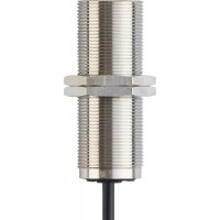
DI5021 - Detector IFM - Free user manual and instructions
Find the device manual for free DI5021 IFM in PDF.


User questions about DI5021 IFM
0 question about this device. Answer the ones you know or ask your own.
Ask a new question about this device
Download the instructions for your Detector in PDF format for free! Find your manual DI5021 - IFM and take your electronic device back in hand. On this page are published all the documents necessary for the use of your device. DI5021 by IFM.
USER MANUAL DI5021 IFM
Operating instructions
Compact speed monitor M30
DC version
DI5020
Contents
1 Preliminary note 3
1.1 Symbols used 3
2 Safety instructions.... 4
3 Intended use.... 5
4 Function 6
4.1 Switching function normally open 6
4.2 Damping 6
4.3 Function diagram 6
5 Installation.... 7
6 Electrical connection.... 8
7 Settings.... 9
7.1 Fine adjustment of switch point as normally open 9
8 Operation 10
9 Maintenance, repair and disposal 11
1 Preliminary note
You will find instructions, technical data, approvals and further information using the QR code on the unit / packaging or at documentation.ifm.com.
1.1 Symbols used
√ Requirement
Instructions
Reaction, result
[...] Designation of keys, buttons or indications
→ Cross-reference

Important note
Non-compliance may result in malfunction or interference.

Information
Supplementary note
2 Safety instructions
- The unit described is a subcomponent for integration into a system.
- The system architect is responsible for the safety of the system.
-
The system architect undertakes to perform a risk assessment and to create documentation in accordance with legal and normative requirements to be provided to the operator and user of the system. This documentation must contain all necessary information and safety instructions for the operator, the user and, if applicable, for any service personnel authorised by the architect of the system.
-
Read this document before setting up the product and keep it during the entire service life.
- The product must be suitable for the corresponding applications and environmental conditions without any restrictions.
- Only use the product for its intended purpose (→ Intended use).
- If the operating instructions or the technical data are not adhered to, personal injury and/or damage to property may occur.
- The manufacturer assumes no liability or warranty for any consequences caused by tampering with the product or incorrect use by the operator.
- Installation, electrical connection, set-up, operation and maintenance of the product must be carried out by qualified personnel authorised by the machine operator.
- Protect units and cables against damage.
• Store the product in its original packaging.
3 Intended use
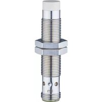
The device detects without contact if a set rotational speed is not reached and signals this by means of a switching signal.
4 Function
4.1 Switching function normally open
| Transistor output | LED green | Description |
| Switched (conducting) | On | Rotational speed > SP + Hy and during the start-up delay |
| Not switched (non conducting) | Off | Rotational speed < SP |
SP = switch point
HY = hysteresis
4.2 Damping
The yellow LED indicates the damping status of the sensor irrespective of either the switching function or the switching status of the transistor output.
| Sensor state | LED yellow |
| Undamped | Off |
| Damped | On |
4.3 Function diagram

1: Voltage supply
2: Start-up delay
3: Switching function normally open
SP: Switch point
Hy: Hysteresis
= transistor output switched (conducting)
The start-up delay suppresses an error message as long as the machine is in the process of starting and has not yet reached its minimum speed. After application of the voltage supply the start-up delay is effective only once.
If the plant is started and stopped frequently, linking the voltage supply of the drive and the speed monitor ensures that the start-up delay is effective each time the machine is switched on.
5 Installation

Fig. 1: Mounting principle

Fig. 2: Mounting specifications
▶ Fix the device using a mounting bracket and secure it by means of the nuts provided so that it cannot work loose.
▶ Adhere to the above mounting specifications to ensure a correct function.
▶ Install the unit flush.
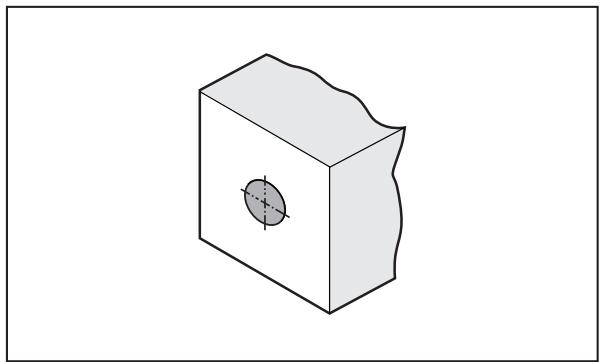
Fig. 3: Cylindrical design, flush
6 Electrical connection

The unit must be connected by a qualified electrician.
▶ Observe the national and international regulations for the installation of electrical equipment.
▶ Disconnect power.
▶ Connect the unit as follows:

BK: black
BN: brown
BU: blue
7 Settings

Fig. 4: Operating and display elements
▶ Keep the minimum speed to be monitored in the plant on a constant level.
▶ Connect the device to the supply voltage.
▶ Wait until the start-up delay is over.
▶ Set the switch point depending on the status of the green LED.
7.1 Fine adjustment of switch point as normally open
When the green LED is off:
▶ Turn the potentiometer slowly anticlockwise (-) until the green LED is on.
▷ Setting is finished.
When the green LED is on:
▶ Turn the potentiometer clockwise (+) until the green LED is off.
▶ Turn the potentiometer slowly anticlockwise (-) until the green LED is on.
▷ Setting is finished.
1: Multi-turn potentiometer for switch point setting (without end stop)
2: LEDs:
- Green LED for switching status indication → Function
- Yellow LED for damping indication (input signal) → Damping
8 Operation
The operation is maintenance-free.
Ensure the following for a correct function:
▶ Keep the sensing face and the clear space free of metal deposits and foreign bodies.
▶ Do not operate devices with high field intensity (e.g. mobile phones) at close range to the speed monitor.
9 Maintenance, repair and disposal
The operation of the unit is maintenance-free.
Only the manufacturer is allowed to repair the unit.
▶ After use dispose of the device in an environmentally friendly way in accordance with the applicable national regulations.
- 1 PRELIMINARY NOTE
- 1.1 SYMBOLS USED
- 2 SAFETY INSTRUCTIONS
- 3 INTENDED USE
- 4 FUNCTION
- 4.1 SWITCHING FUNCTION NORMALLY OPEN
- 4.2 DAMPING
- 4.3 FUNCTION DIAGRAM
- 5 INSTALLATION
- 6 ELECTRICAL CONNECTION
- 7 SETTINGS
- 7.1 FINE ADJUSTMENT OF SWITCH POINT AS NORMALLY OPEN
- 8 OPERATION
- 9 MAINTENANCE, REPAIR AND DISPOSAL
Brand : IFM
Model : DI5021
Category : Detector