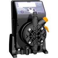
57893 - Water pump ASTRALPOOL - Free user manual and instructions
Find the device manual for free 57893 ASTRALPOOL in PDF.


| Product type | Diaphragm dosing pump |
| Brand | AstralPool |
| Model | 57893 |
| Intended use | Dosing of liquids (water, reagents) |
| Maximum flow rate | 20 L/h (depending on model) |
| Maximum pressure | 15 bar (depending on model) |
| Standard power supply | 230 V AC 50 Hz single phase |
| Protection rating | IP65 |
| Housing material | Acid-resistant reinforced polypropylene |
| Diaphragm material | PTFE |
| Pump head material | Polypropylene (options: PVC, stainless steel 316, PTFE) |
| Fittings material | Polypropylene (options: PVC, stainless steel 316, PTFE) |
| Valve material | Viton (options: silicone, EPDM, nitrile, glass/stainless steel ball) |
| Net weight | 2.7 to 4.1 kg depending on model |
| Power consumption | 37 to 82 W depending on model |
| Current consumption | 0.16 to 0.36 A |
| Maximum suction height | 2 m |
| Dose per stroke | 0.28 to 2.80 ml |
| Ambient operating temperature | Max 40 °C (min according to liquid) |
| Flow rate adjustment | Manual via potentiometer (0 to 100 %) |
| Level control | Optional (float switch not supplied) |
| Maintenance | Periodic cleaning of valves and filter; check seals every 6 months |
| Safety | Disconnect before servicing; use PPE for hazardous liquids |
| Warranty | 2 years (excluding wear parts) |
Frequently Asked Questions - 57893 ASTRALPOOL
User questions about 57893 ASTRALPOOL
0 question about this device. Answer the ones you know or ask your own.
Ask a new question about this device
Download the instructions for your Water pump in PDF format for free! Find your manual 57893 - ASTRALPOOL and take your electronic device back in hand. On this page are published all the documents necessary for the use of your device. 57893 by ASTRALPOOL.
USER MANUAL 57893 ASTRALPOOL
natural_image
Exterior view of a black ASTRALPOOL industrial pump with control panel and orange valve (no visible text or symbols on the device itself)ASISTENCIA TECNICA Y OFICINAS COMERCIALES TECHNICAL ASSISTANCE AND SALES OFFICES ASSISTENZA TECNICA E UFFICI COMMERCIALI
GRAFICO CLORO LIBERO VS POTENZIALE REDOX (pH)
GRAPHIQUE CHLORE LIBRE VS POTENTIEL REDOX (pH)
GRAFIK FREIES CHLOR ZU REDOX-POTENTIAL (Ph)
GRÁFICO CLORO LIVRE - POTENCIAL REDOX (pH)
GRÁFICO CLORO LIBRE VS POTENCIAL REDOX (pH)
FREE CHLORINE - OXIDATION REDUCTION POTENTIAL (ORP) - pH SKETCH
(ppm)
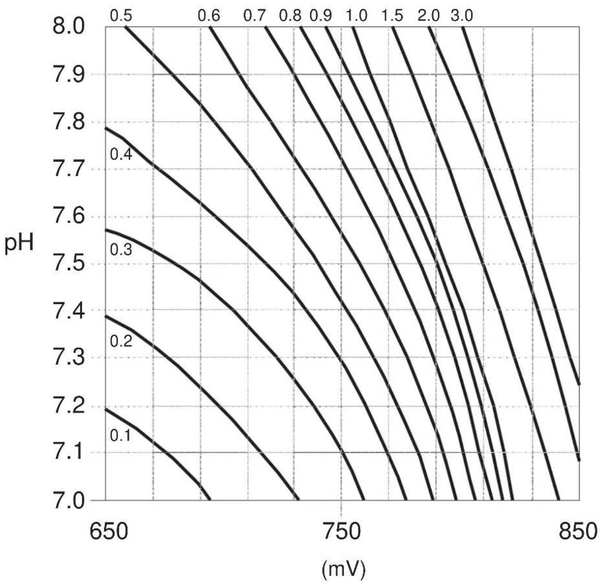
contour
| pH | 650 (mV) | 750 (mV) | 850 (mV) | |------|----------|----------|----------| | 7.0 | 650 | 750 | 850 | | 7.1 | 650 | 750 | 850 | | 7.2 | 650 | 750 | 850 | | 7.3 | 650 | 750 | 850 | | 7.4 | 650 | 750 | 850 | | 7.5 | 650 | 750 | 850 | | 7.6 | 650 | 750 | 850 | | 7.7 | 650 | 750 | 850 | | 7.8 | 650 | 750 | 850 | | 7.9 | 650 | 750 | 850 | | 8.0 | 650 | 750 | 850 |INDICE
1.0 -NORMAS GENERALES pag. 2
natural_image
Technical line drawing of a mechanical device with tubing and a water tank (no text or symbols)Fig. 5
flowchart
graph TD
    A["Feed Inlet"] --> B["Pump"]
    B --> C["Control Unit"]
    C --> D["Water Body"]
    D --> E["Outlet"]
    style A fill:#f9f,stroke:#333
    style E fill:#bbf,stroke:#333
Fig. 6
natural_image
Four-step diagram showing a mechanical device with a lever and handle, illustrating the process (no text or symbols)Fig. 7
Fig. 9
natural_image
Exploded view diagram of a mechanical assembly with multiple components (no text or labels)Fig. 11
Fig. 18
9.0 - BOMBA DOSIFICADORA CON MICROCONTROLADOR SERIE EXACTUS VFT/MBB
Please read the warning notices given in this section very carefully, because they provide important information regarding safety in installation, use and maintenance of the pump.
- Keep this manual in a safe place, so that it will always be available for further consultation.
- The pump complies with EEC directives No.89/336 regarding "electromagnetic compatibility" and No.73/23 regarding "low voltages", as also the subsequent modification No.93/68.
N.B. The pump has been constructed in accordance with best practice. Both its life and it electrical and mechanical reliability will be enhanced if it is correctly used and subjected to regular maintenance.
1.1 - WARNING:
Any intervention or repair to the internal parts of the pump must be carried out by qualified and authorized personnel. The manufacturers decline all responsibility for the consequences of failure to respect this rule.
GUARANTEE: 2 years (the normal wearing parts are excluded, i.e.: valves, nipples, tube nuts, tubing, filter and injection valve). Improper use of the equipment invalidates the above guarantee. The guarantee is exfactory or authorized distributors.
1.2 - SHIPPING AND TRANSPORTING THE PUMP
The pump should always be moved in a vertical (and never in a horizontal) position. No matter what the means of transport employed, delivery of the pump, even when free to the purchaser's or the addressee's domicile, is always at the purchaser's risk. Claims for any missing materials must be made within 10 (ten) days of arrival, while claims for defective materials will be considered up to the 30th (thirtieth) day following receipt. Return of pumps or other materials to us or the authorized distributor must be agreed beforehand with the responsible personnel.
1.3 - PROPER USE OF THE PUMP
- The pump should be used only for the purpose for which it has been expressly designed, namely the dosing of liquid additives. Any different use is to be considered improper and therefore dangerous. The pump should not therefore be used for applications that were not allowed for in its design. In case of doubt, please contact our offices for further information about the characteristics of the pump and its proper use.
The manufactures cannot be held responsible for damage deriving from improper, erroneous or unreasonable use of the pump.
1.4 - RISKS
- After unpacking the pump, make sure it is completely sound. In case of doubt, do not use the pump and contact qualified personnel. The packing materials (especially bags made of plastics, polystyrene, etc.) should be kept out of the reach of children: they constitute potential sources of danger.
- Before you connect the pump, make sure that the voltage ratings, etc., correspond to your particular power supply. You will find these values on the rating plate attached to the pump.
- The electrical installation to which the pump is connected must comply with the standards and good practice rule in force in the country under consideration.
- Use of electrical equipment always implies observance of some basic rules: In particular:
1 - do not touch the equipment with wet or damp hands or feet;
2 - do not operate the pump with bare feet (Example: swimming pool equipment);
3 - do not leave the equipment exposed to the action of the atmospheric agents;
4 - do not allow the pump to be used by children or unskilled individuals without supervision;
- In case of breakdown or improper functioning of the pump, switch off, but do not touch. Contact our technical assistance for any necessary repairs and insist on the use of original spares. Failure to respect this condition could render the pump unsafe for use.
- When you decide to make no further use of an installed pump, make sure to disconnect it from the power supply.
Before carrying out any service on the item, check:
- Disconnect the pins from the mains or by means of a two poles switch with 3 mm minimum distance between the contacts. (Fig. 4).
- Relieve all the pressure from the pump head and injection tube.
- Drain or flush all dosing liquid from the pump head. This operation can also be done with the pump disconnected from the plant by turning the pump upside-down for 15 to 30 seconds and without connecting the tubing to the nipples: if this operation is not possible, dismount and remount the pump head using the four mounting screws.
In event of possible losses in the hydraulic system of the pump (breakage of the "0" ring gasket, the valves or the hoses) the pump should immediately be brought to a stop, emptying and depressurizing the delivery hose while taking all due safety precautions (gloves, goggles, overalls, etc.).
1.5 - TOXIC AND/OR DANGEROUS LIQUID DOSAGE
To avoid risk from contact with the hazardous liquids or toxic fumes, always adhere to the notes in this instruction manual:
- Follow the instructions of the dosing liquid manufacturer.
- Check the hydraulic part of the pump and use it only if it is in perfect condition.
- Use only the correct materials for the tubing, valves and seals to suit the liquid to be dosed; where possible shield the tubing with PVC conduit.
- Before disconnecting the metering pump, make sure to flush out and neutralize the pump head with the proper reagent liquid.
1.6 - ASSEMBLING AND DISMANTLING THE PUMP
1.6.1 - ASSEMBLY
All metering pumps are normally supplied fully assembled. For greater clarity, please consult the exploded view of the pump appended at the end of the manual, which shows all the pump details and a complete overview of all the pump components. These drawings are in any case quite indispensable whenever defective parts have to be re-ordered. For the same purpose, the appendix also contains other drawings showing the hydraulic parts (pump head and valves).
1.6.2 - DISMANTLEMENT
Proceed as follows before you dismantle the pump or before performing any other operation on it:
- Disconnect the pins from the mains or by means of atwo poles switch with 3 mm minimum distance between the contacts. (Fig. 4).
- Relieve all the pressure from the pump head and injection tube.
- Drain or flush all dosing liquid from the pump head. This operation can also be done with the pump disconnected from the plant by turning the pump upside-down for 15 to 30 seconds and without connecting the tubing to the nipples: if this operation is not possible, dismount and remount the pump head using the four mounting screws. (Fig. 11).
This operation calls for special attention, and you should therefore consult the drawings in Appendix and Chapter 1.4 "RISKS" before you commence work.
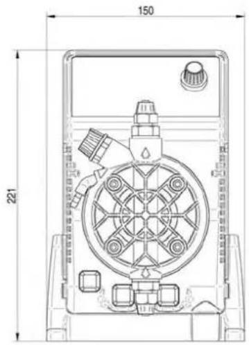
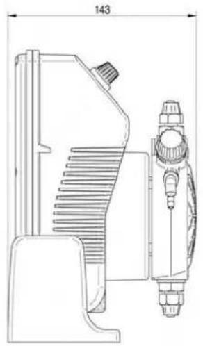
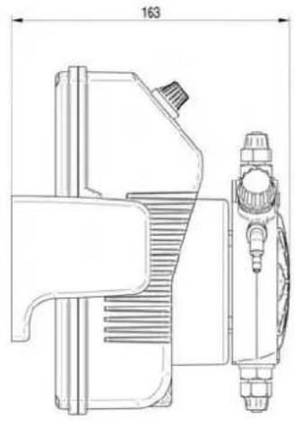
OVERALL DIMENSIONS (Fig. 1)
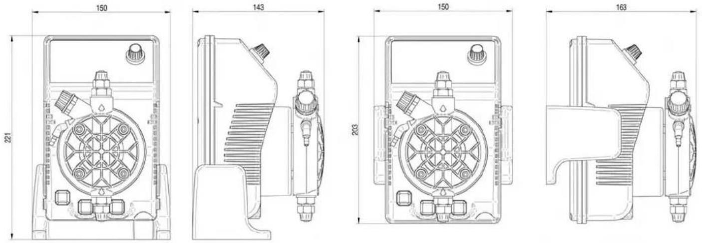
2.0 - EXACTUS SERIES METERING PUMPS
2.1 - OPERATION
The metering pump is activated by a teflon® diaphragm mounted on a piston of an electromagnet.
When the piston of the electromagnet is attracted, a pressure is produced in the pump body with an expulsion of liquid from the discharge valve. Once the electric impulse is finished a spring brings the piston back to the initial position, with a recall of liquid through the suction valve.
The operation is simple the pump does not need lubrication, therefore maintenance is reduced almost to zero. The materials used for the construction of the pump make it particularly suitable for aggressive liquids.
The metering pump has been designed to feed liquids with capacities from 0 to 20 l/h and pressures from 0 to 10 bar (depending on the model selected).
2.2 - COMMON FEATURES
• The products are manufactured according (€) regulation.
• IP 65 protection.
• Antiacid plastic casing.
• Control panel protection assured by an adhesive polyester film, weatherproof and resisting UV rays
• Standard powersupply:
230 Va.c.50 Hz single phase.
• Optional power supply:
240 Va.c.50-60 Hz single phase;
110 Va.c. 50-60 Hz single phase.
UPON REQUEST:
- Level control setting included (supplied without probe).
2.3 - LIQUID ENDS MATERIALS
DIAPHRAGM: PTFE
PUMP HEAD: Polypropylene; upon request: PVC, 316 Stainless, PTFE
NIPPLES: polypropylene
FILTER: polypropylene
INJECTION NIPPLE: polypropylene
SUCTION HOSE: PVC - flexible
DISCHARGE HOSE: polyethylene
VALVES "lip" type: FPM (viton®), (upon request available in EPDM (Dutral®), NBR, Silycon). "Ball Check" VALVES
upon request type in SS316 and Glass PYREX. Available with Spring Return and "KALRETZ"Valve.
SEALS: FPM upon request EPDM, NBR, Silycon, PTFE only for ball checks valves
MAIN FEATURES
| Tipo Type | Portata max Max flow | Press. max Max press | Max imp./min. Max imp./min. | Dosaggio per imp. Output per stroke | Corsa Stroke | Altez. aspiraz. Suction height | Aliment. elettr. standard Standard power supply | Potenza ass. Power cons. | Correnteass. Current cons. | Peso netto Net weight |
| l/h | bar | ml | mm | m | Volts/Hz | Watts | Ampere | kg | ||
| 2-5 | 2 | 5 | 120 | 0,28 | 0,80 | 2 | 230 V 50-60 Hz | 37 | 0,16 | 2,7 |
| 2-10 | 2 | 10 | 120 | 0,28 | 1,20 | 2 | 230 V 50-60 Hz | 37 | 0,16 | 2,7 |
| 4-5 | 4 | 5 | 120 | 0,56 | 1,00 | 2 | 230 V 50-60 Hz | 37 | 0,16 | 2,7 |
| 5-7 | 5 | 7 | 120 | 0,70 | 1,40 | 2 | 230 V 50-60 Hz | 37 | 0,16 | 2,7 |
| 5-10 | 5 | 10 | 120 | 0,70 | 1,80 | 2 | 230 V 50-60 Hz | 58 | 0,25 | 3,2 |
| 10-5 | 10 | 5 | 120 | 1,40 | 1,10 | 2 | 230 V 50-60 Hz | 58 | 0,25 | 3,2 |
| 10-10 | 10 | 10 | 120 | 1,40 | 2,20 | 2 | 230 V 50-60 Hz | 82 | 0,36 | 4,1 |
| 20-5 | 20 | 5 | 120 | 2,80 | 2,00 | 2 | 230 V 50-60 Hz | 82 | 0,36 | 4,1 |
Fig. 2
line
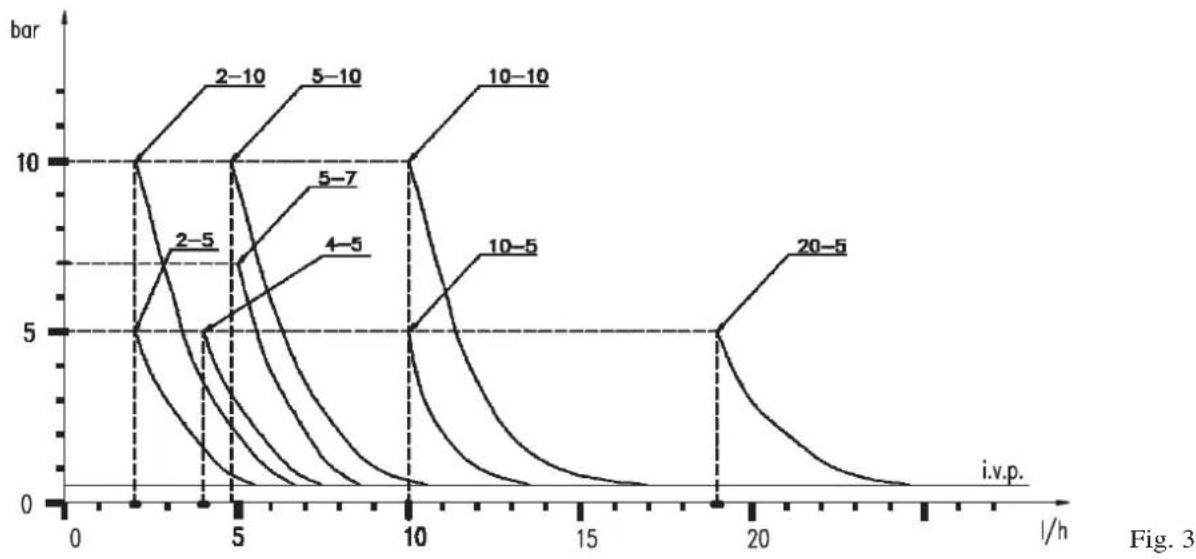
| i.v.p. | Bar Value | | ------ | --------- | | 2-5 | 5 | | 4-5 | 5 | | 5-7 | 7 | | 10-10 | 10 | | 10-5 | 5 | | 20-5 | 5 |The diagrams of fig. 3 indicate max metering pump flow variation in relation to the working pressure in the plant; the diagrams also include injection valve losses. I.V.P.
Due to production requirements the technical characteristics of our equipment at maximum ratings can vary with a tolerance of 5% which must be taken into account when choosing the type of pump.
a. - Install the pump in a dry place and well away from sources of heat and, in any case, at environmental temperatures not exceeding 40^ C. The minimum operating temperature depends on the liquid to be pumped, bearing in mind that it must always remain in a liquid state.
b. - Carefully observe the regulations in force in the various countries as regards electrical installations (Fig.4). When the supply cable is devoid of a plug, the equipment should be connected to the supply mains by means of a single-pole circuit breaker having a minimum distance of 3 mm between the contacts. Before accessing any of the electrical parts, make sure that all the supply circuits are open.
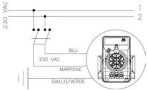
Fig. 4
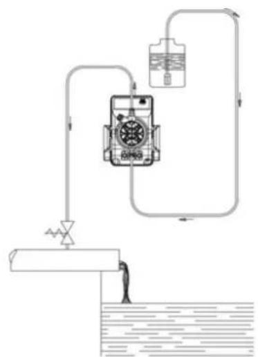
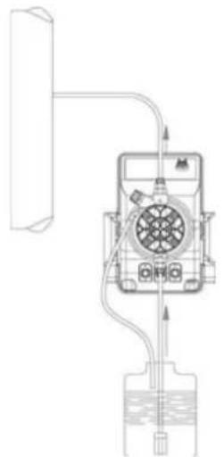
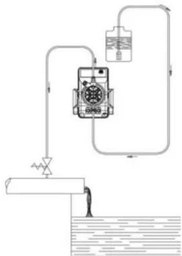
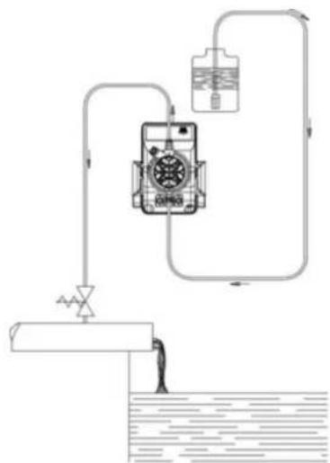
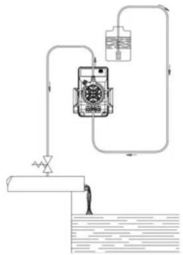
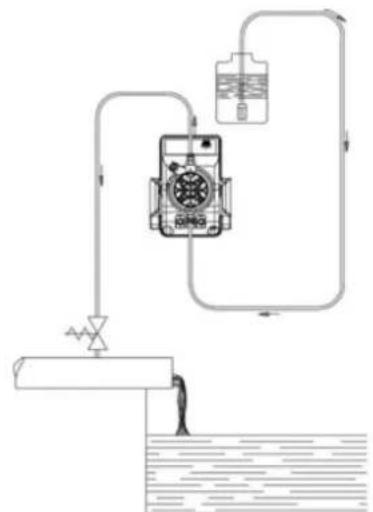
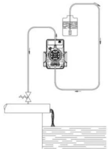
c.- Locate the pump as shown in fig. 5 bearing in mind that it may be installed either below or above the level of the liquid to be dosed, though the level difference should not exceed 2 meters. When the process plant in which the pump is installed is operating at atmospheric pressure (no back pressure) and the chemical tank is situated above the plant (Fig. 6), the condition of the injection valve should be checked at regular intervals, because excessive wear and tear could cause additive to drip into the plant even when the pump is shut down. If the problem persist, install a properly calibrate counter-pressure valve (C) between injection point and the valve. In the case of liquids that generate aggressive vapours, do not install the pump above the storage tank unless the latter is hermetically sealed.
natural_image
Technical line drawing of a mechanical device with tubing and a water tank (no text or symbols)Fig. 5
flowchart
graph TD
    A["Feed Inlet"] --> B["Pump"]
    B --> C["Valve"]
    C --> D["Water Tank"]
    D --> E["Outlet"]
    style A fill:#f9f,stroke:#333
    style E fill:#bbf,stroke:#333
Fig. 6
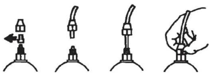
d.- The discharge nipple will always remain in the upper part of the pump. The suction nipple, which serves to attach the hose (with filter) leading into the chemical tank, will therefore always be situated in the lower part of the pump.
natural_image
Four-step diagram showing a mechanical device with a lever and handle, no text or symbols presentFig. 7
e.- Remove the protection caps from the two nipples, slide the hoses over the connectors, pushing them right home, and then fix them with appropriate tube nuts. (Fig. 7).
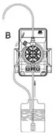
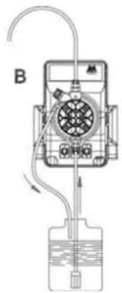
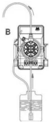
Fig. 8
Whenever the pump is dismantled from the pipework, you will be well advised to replace the caps on the connectors to avoid residual liquid being spilled. Before attaching the delivery hose to the plant, prime the metering pump by going through the sequence shown in Fig. 8. Before finalizing the installation of the discharge hose, make sure that the pump strokes will not cause it to move and bump into rigid bodies. In case of priming difficulties, use a normal syringe to suck liquid from the discharge nipple while the pump is in operation, continuing until you actually see the liquid rise in the syringe. Use a short length of suction hose to connect the syringe to the discharge nipple. In case of a pump equipped with an air bleed valve, unscrew the air relief valve B up to all the air in the pump head will be out.
f. - Try to keep both the suction and discharge hose as straight as possible, avoiding all unnecessary bends.
g. - Select the most appropriate injection point on a pipe of the plant to be treated and there fit a 3/8" female steel gas thread connector (similar to BSPm). This connector is not supplied with the pump. Screw the injection valve to the gas connector, inserting a gasket as shown in Fig. 9. Then connect the discharge hose to the conical connector on the injection valve and fix it with the supplied tube nut G. The injection valve also acts as no return valve by means of a cylinder sleeve (elastomer, standard supplied in Viton®).
N.B. The sleeve D must not be removed.
3.1 - INJECTION VALVE INSTALLATION DIAGRAM Fig. 9
A - Pipework
C- Injection valve
M - Conical connector for attaching the discharge hose
N - 3/8" female steel gas thread connector
G - Hose tube nut
T - Polyethylene hose
D - Cylinder sleeve (no return valve)
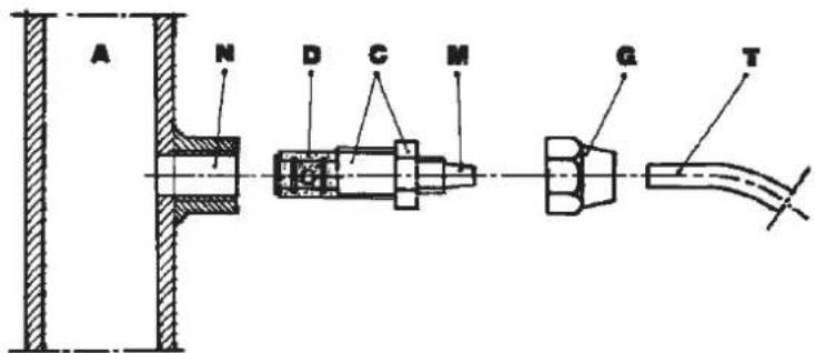
Fig. 9
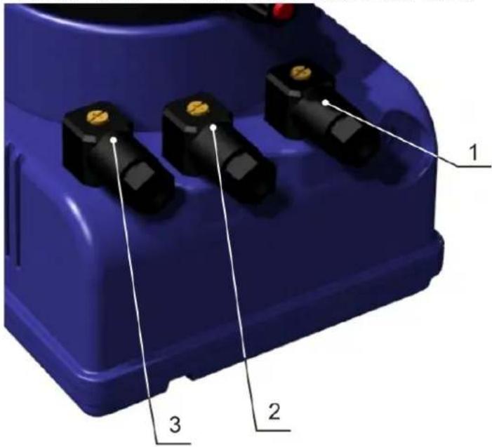
3.2 - WIRING CONNECTION AND OUTPUT CONNECTOR FUNCTIONS
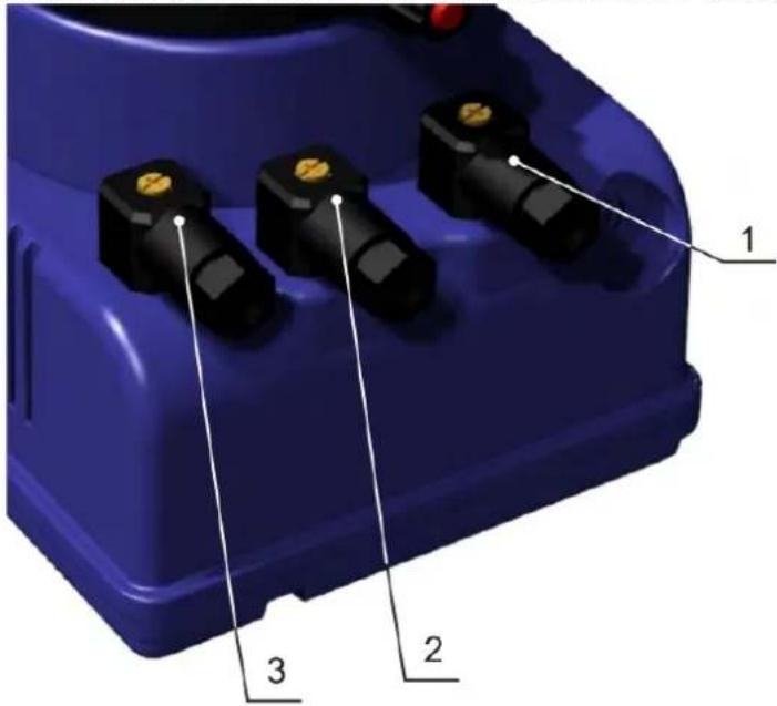
Fig. 10
| Model | Female service connector wire assembly | Functions and technical informations | |
| VFT/MBB | 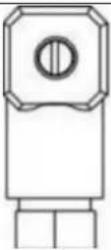 | 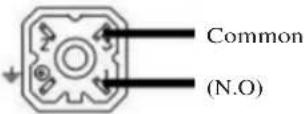 POS. 1 POS. 1 | Relay service output connectionConfiguration:Pin 1 = Normally Open“ 2 = No connection“ 3 = Common = = No connection |
| MA/ADL MA/MB CC/M VFT/MBB |  [IMAGE] [IMAGE] | 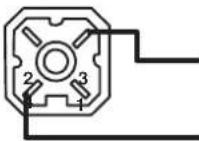 To level probePOS. 2 To level probePOS. 2 | Level probeconnectionConfiguration:Pin 1 = No connection“ 2 = No connection“ 3 = Level probe wire“ 4 = Level probe wire |
| CC/M |  ‘ | ‘ ‘ | ‘ | 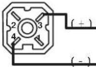 Input mA signalPOS. 3 Input mA signalPOS. 3 | Input mA signal configuration:Pin 1 = No connection“ 2 = No connection“ 3 = (+) mA signal wire“ 4 = (-) mA signal wire |
| VFT/MBB |  [IMAGE] [IMAGE] | 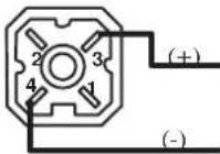 To pulse emitting water meterPOS. 3 To pulse emitting water meterPOS. 3 | Pulse emitting Water Meter connectionConfiguration:Pin 1 = No connection“ 2 = No connection“ 3 = Water meter signal wire (+)“ 4 = Water meter signal wire (-) |
- Periodically check the chemical tank level to avoid the pump operating without liquid. This would not damage the pump, but may damage the process plant due to lack of chemicals.
- Check the pump operating condition at least every 6 months, pump head position, screws, bolts and seals; check more frequently where aggressive chemicals are pumped, especially:
- pulse and power L.E.D.;
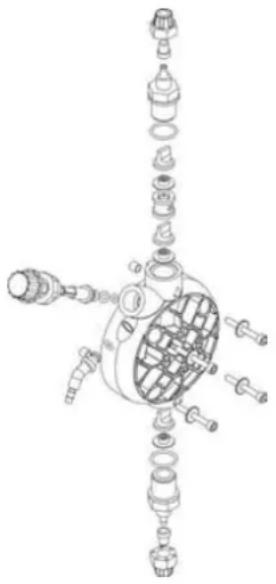
- the additive concentration in the pipework; a reduction of this concentration could be caused by the wearing of the valves, in which case they need to be replaced (Fig. 11) or by the clogging of the filter which then has to be cleaned as in point 3 here below.
natural_image
Exploded view diagram of a mechanical assembly with internal components (no text or labels)Fig. 11
- The Company suggests periodically cleaning off the hydraulic parts (valves and filter). We cannot say how often this cleaning should be done as it depends on the type of application, we also cannot suggest what cleaning agent to use as this will depend on the additive used.
Operating suggestions when dosing sodium hypochlorite (most frequent case):
a - disconnect the pins from the mains or by means of a onnipolar switch with 3 mm minimum distance between the contact.
b - disconnect discharge hose from pipework;
c - remove the suction hose (with filter) from the tank and dip it into clean water;
d- switch on the metering pump and let it operate with water for 5 to 10 minutes;
e - switch OFF the pump, dip the filter into a hydrochloric acid solution and wait until the acid finishes cleaning;
f- switch ON the pump again and operate it with hydrochloric acid for 5 minutes in a closed-circuit, with suction and discharge hose dipped into the same tank;
g - repeat the operation with water;
h - re-connect the metering pump to the pipework.
5.0 - HOW TO OPERATE WHEN DOSING SULPHURIC ACID (MAX 50%)
In this case it is essential to bear in mind the following:
-
replace PVC crystal suction hose with polyethilene discharge hose;
-
empty any residual water from the pump head beforehand.
Warning: if the water mixes with sulphuric acid it can produce a large quantity of gas with consequent overheating of the area causing damage to valves and pump head.
This operation can also be done with the pump disconnected from the plant by turning the pump upside-down for 15 to 30 seconds and without connecting the hose to the nipples; if impossible, dismount and remount the pump head (Fig. 11) using the four mounting screws.
EXACTUS MA/AD
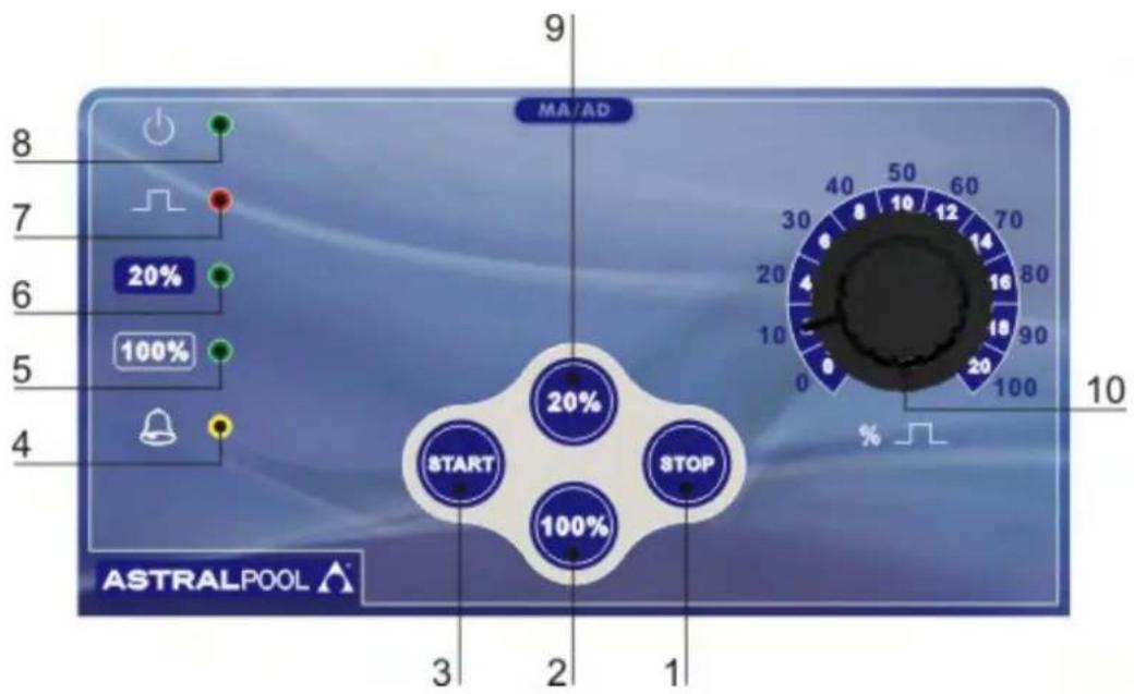
Fig. 12
6.0 - MANUALLY OPERATED METERING PUMP EXACTUS MA/AD SERIES
Flow can be controlled manually by setting the pump pulse rate by means of a potentiometer. Possibility of a more precise flow rate setting at low frequencies through the two keys 20% and 100%.
6.1 - PUMP CONTROLS (Fig.12)
1 - Switch off button "STOP"
2 - 100% flow scale read out button
3 - Switch on button "START"
4 - Level alarm LED "yellow" (only for EXACTUS with level alarm, MA/ADL SERIES)
5 - 100% flow scale read out LED "green"
6 - 20% flow scale read out LED "green"
7 - Pulse LED "red"
8 - Power LED "green"
9 - 20% flow scale read out button
10 - Adjustment knob of Injections/min numbers (0÷100% max flow)
6.2 - TYPICAL INSTALLATION (Fig.13)
A Injection valve
B Power supply
C Filter
I Chemical tank
S Process tank
6.3 - ACCESSORIES
• 1 flexible PVC suction hose,
transparent crystal type, length 2 m;
• 1 semirigid polyethylene hose, white, length 2 m;
• 1 injection valve 3/8 BSP m;
• 1 filter;
• 1 instructions/operating booklet.
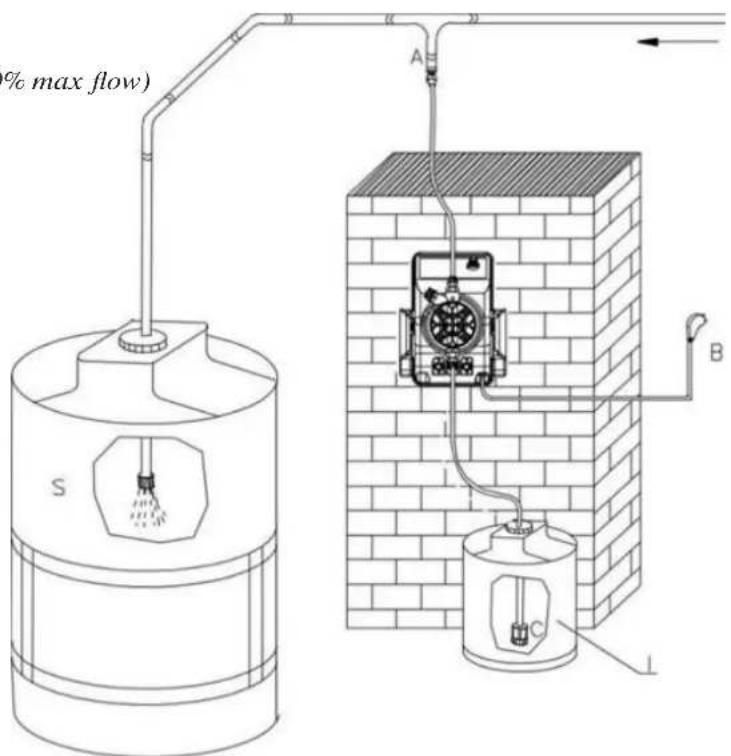
Fig. 13
EXACTUS MA/MB
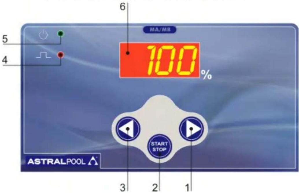
Fig. 14
7.0 - MICROCONTROLLED DOSING PUMPS EXACTUS MA/MB SERIES
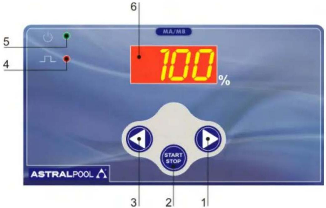
Manual flow rate adjustment by means 2 buttons (LEFT (3) - RIGHT (1)) shown in figure 14.
Operative range 1-100% flow rate.
7.1 - PUMP CONTROLS (Fig. 14)
1 - Increasing values button
2 - ON/STAND BY button
3 - Decreasing values button
4 - "red" LED injection pulse flashing
5 - "green/red" LED pump fed/stand by - level probe alarm
6 - 7 segment display
7.2 - TYPICAL INSTALLATION (Fig.15)
A Injection valve
B Power supply
C Filter
S Process tank
I Chemical tank
7.3 - ACCESSORIES
• 1 flexible PVC suction hose,
transparent crystal type, length 2m;
• 1 semirigid polyethylene hose, white, length 2 m;
• 1 injection valve 3/8 BSP m;
- 1 filter;
• 1 instructions/operating booklet.
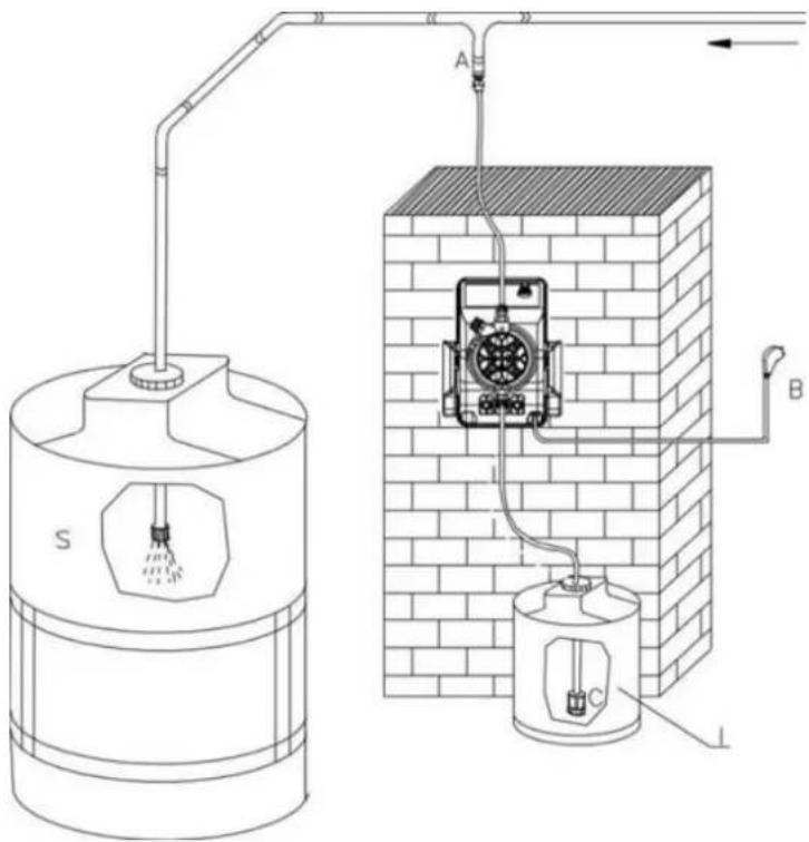
Fig. 15
EXACTUS CC/M
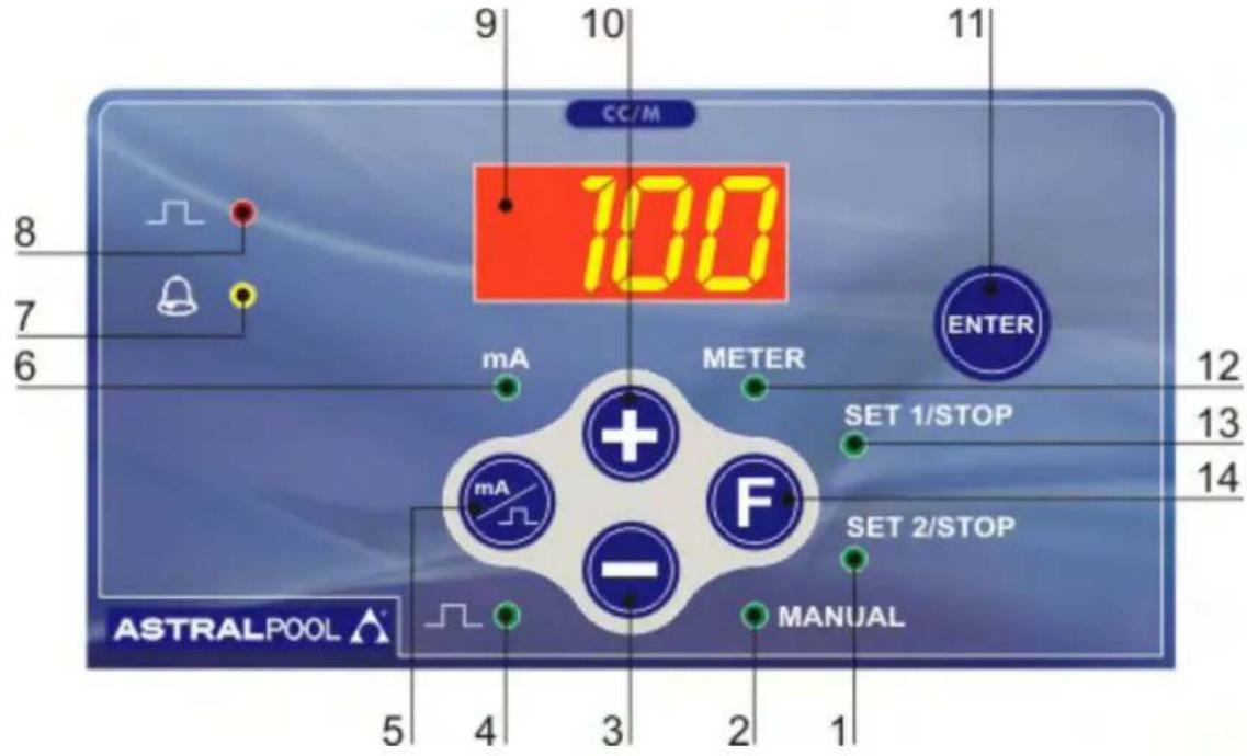
Fig. 16
8.0 - MICROCONTROLLED DOSING PUMPS EXACTUS CC/M SERIES
The EXACTUS CC dosing pump is a microcontroller unit suitable for operation in proportion to a "mA" input signal. Connected to a transmitter/indicator instrument or other device which supplies a modulated current signal from 0 to 20 mA, the pump pulse frequency will be proportional to the mA signal received: higher the signal higher the pump flow.
8.1 - PUMP CONTROLS (Fig. 16)
1 - "green" LED SET POINT2 function/stand by
2 - "green" LED MANUAL function
3 - Decreasing values button
4 - "green" LED stroke
5 - "Functions selector (mA/manual pulse)
6 - "green" LED mA
7 - "yellow" LED level probe alarm
8 - "red" LED injection pulse flashing
9 - 7 segment display
10 - Increasing values button
11 - Enter button
12 - "green" LED METER function
13 - "green" LED SET POINT1 function/stand by
14 - Function selection button
8.2 - TYPICAL INSTALLATION (Fig.17)
A Injection valve
B Power supply
C Filter
D Level probe
I Chemical tank
S Process tank
8.3 - ACCESSORIES
• 1 flexible PVC suction hose,
transparent crystal type, length 2 m;
• 1 semirigid polyethylene hose, white, length 2 m;
• 1 injection valve 3/8 BSP m;
- I filter;
• 1 instructions/operating booklet.
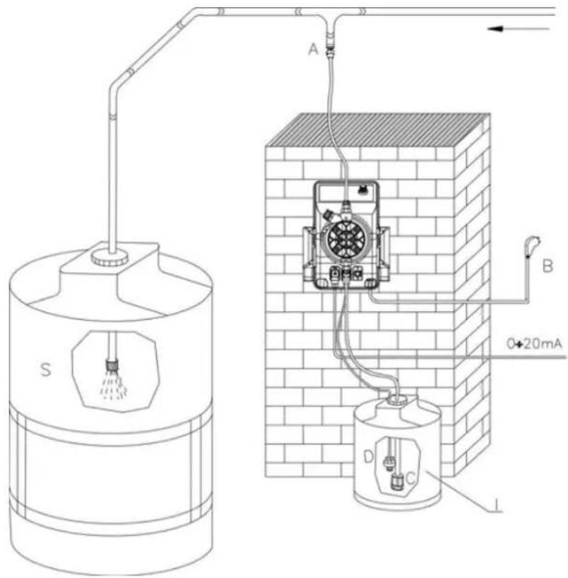
Fig. 17
8.4 - LEVEL CONTROL (UPON REQUEST)
If the dosing pump is supplied with level control setting and upon request floating level switch. When the level of the additive is lower than the switch, level alarm goes ON, the display will show "FAO", the pump is off giving an optical and soundalarm. The level control alarm goes ON with 5 seconds delay.
8.5 - CALIBRATION
Turning on the pump, the instrument switches automatically to the "METER" function.
Pressing button mA pulse (5) will show the actual mA input signal. To go back to strokes/min press again. The manual function is also used when priming the pump. In order to avoid programming and setting errors during the system functioning, the pump is programmed to automatically return to the Meter Mode each time the unit is switched OFF.
8.6 - PARAMETERS SETTING MODE (Fig. 16)
- “Manual” Mode
Turn pump ON
A. On the control panel press button F (14) and start manual mode: ("Manual" LED 2 ON)
B. By means of button 10 (increase) and 3 (decrease), select the number of imp/min. To prime the pump set pulse rate at 75%.
C. Prime the pump.
- “Set 1” Mode
Mode Set 1 is used to select the mA input value/min. dosing pump flow and pulse frequency.
A. Press button 14; Set 1, LED ON. The display will show the pulse frequency previously set.
B. Select the minimum pump output required pressing buttons 3 and 10. If the minimum output is zero set 000.
C. Press button 5 "mA" LED ON:
D. By pressing buttons 3 and 10, you can select the mA input value corresponding to minimum pump output required. Confirm with enter 11. To finish the programming procedure and modify the maximum output value, press button 14 which will automatically change to mode Set 2.
- "Set 2" Mode
Mode Set 2 selects the mA input value/max. dosing pump flow and pulse/frequency.
A. Press button 14 Set 2 LED ON, the display will show the frequency previously set.
B. Press buttons 3 and 10 to set the desired imp/frequency at the maximum pump output required.
C. Press button 5 "mA/pulse", the display will show the value previously set.
D. Pressing 3 and 10 select the mA input value at the maximum pump output required.
E. Press button 11 to enter. The pump will automatically return to “METER” mode and is operational according to the selected functioning mode; two modes are available: direct/reverse.
- Direct Functioning Mode
During production the pumps are programmed for a 4-20 mA direct functioning curve. The pump will start every time the mA signal goes above 4 mA increasing the pulse frequency (and consequently the flow) proportionally to the mA input signal up to maximum imp/min frequency available. E.G. Set 1 minimum signal 4 mA, minimum output. Set 2 maximum signal 20 mA, maximum output.
- Reverse Functioning Mode
Reverse functioning is when the mA signal increases and pump output proportionally decreases. Select the maximum mA signal required with mode Set 1 (in relation to the min. output).
E.G. Set 1 maximum signal 20 mA, minimum output.
Set 2 minimum signal 4 mA, maximum output.
WARNING: Reverse functioning can only be selected when mode Set 1 is always higher than the mA signal.
Example n°1: PUMP MODEL EXACTUS-CC, 10 L/H, 5 BAR, SIGNAL 4-20 mA.
Signal 4 mA = 0 l/h (0% pump flow rate)
Signal 12 mA = 5 l/h (50% pump flow rate)
Signal 20 mA = 10 l/h (100% pump flow rate)
Example n° 2: SAME MODEL, BUT WITH INVERSE SIGNAL: 20 - 4 mA
Signal 4 mA = 10 l/h (100% pump flow rate)
Signal 12 mA = 5 l/h (50% pump flow rate)
Signal 20 mA = 0 l/h (0% pump flow rate
EXACTUS VFT/MBB
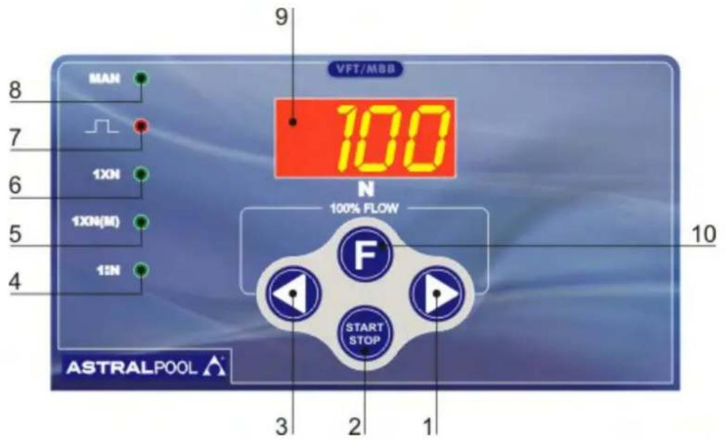
Fig. 18
9.0 - MICROCONTROLLED DOSING PUMPS EXACTUS VFT/MBB SERIES
The pump is equipped with a modern microcontroller allowing design of a extremely compact and reliable electronic device.
9.1 - PUMP CONTROLS (Fig. 18)
1 - Increasing values button
2 - ON/STAND BY button
3 - Decreasing values button
4 - "green" LED 1:N function
5 - "green" LED IXN (M) function/water meter
6 - "green" LED 1XN function/ manual mode
7 - "red" LED injection pulse flashing
8 - "green/red" LED pump fed/stand by
9 - 7 segment display
10 - function selection button
9.2 - TYPICAL INSTALLATION (Fig.19)
A Injection valve
B Power supply
C Filter
D Level probe
I Chemical tank
K Pulse emitting water meter
S Process tank
9.3 - ACCESSORIES
- 1 flexible PVC suction hose, transparent crystal type, length 2 m;
• 1 semirigid polyethylene hose, white, length 2 m;
• 1 injection valve 3/8 BSP m; - 1 filter;
• 1 instructions/operating booklet.
9.4 - LEVEL CONTROL
The dosing pump is supplied with level control setting. When the chemical tank is empty, on display (9) it appears R1 and the pump goes in stand by. The level control has 5 seconds of delay.
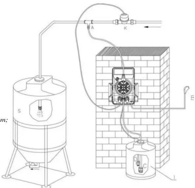
Fig. 19
205 VFT/MBB FEATURE DESCRIPTION
Utilising the "F" function button enables simple selection of one of the below modes. When the LED is energized and
flashing next to the mode required, the operator must adjust the value "N" using the arrows. Setting is confirmed by pressing the START/STOP button.
MANUAL Mode
Unit runs at flow rate set on "N" - adjustable 10-100%
1XN Mode
Let's see how the pumps works with an example:
- Pump set in water meter 1XN mode
- Set value on "20"
- At the time the water meter gives a pulse to the pump, it starts its 20 dosing injection strokes, if during this phase further shuts of the contact occur, these are neglected. Ended up the 20 injections, the pump is waiting for further pulses from the water meter to restart the dosing cycle.
1XN(M) Mode
The pump is operated by an impulse produced by an external device (e.g. pulse emitting water meter) and it supplies a number of injections equal to the value visualized on the display "N" (set by the operator). The injections are distributed with a variable frequency that depends by the time passed between a water meter pulse (produced by water meter) and the other.
Possible impulses (contacts) that may arrive to the pump while is already dosing are saved in the memory of the microcontroller, these will be delivered after the first batch is dosed.
Let's see how the pump works with an example:
The pump receives the first contact and returns a string "N" injections to the maximum frequency (e.g. 120 imps./min).
To the arrival of the second contact, the pump computes the time "T" spent by the arrival of the first one and it returns a string of "N" injections not more to the maximum frequency but to that it allows to uniformly distribute them in the time "T".
In case such time reduces, the pump keeps into consideration the injections "N1" which have not been delivered and add them to the "N" ones still not delivered. There are no problems if the time occurred between the contacts should length. If instead quick contacts occurs and it goes to condition N1>4 times N, the pump goes in alarm (on the display AL3 is visualized) but continues working and maintaining all the parameters set before by the operator but not dosing the strokes related to the last water meter pulses "N".
1:N Mode
The pump supplies an injection of chemical only when it has reached a number of pulses (contacts), equal to the value visualized on the display (set by the operator)
Let's see how it works with an example:
- Pump set with water meter 1:N
- Set value on "20"
- While the water meter supplies 20 pulses the pump discharge 1 stroke.
PRIMING (100% flow)
is possible in all meter modes by pressing and holding simultaneously.


980 INPUT/OUTPUT EXTERNAL CONNECTIONS (FOR EXTERNAL ACCESSORY)
As shows on paragraph 3.2 the three connectors are used for connecting the accessories.
Namely the accessories are:
- Level control switch;
- Water meter input (Reed switch type);
- Output service relay
It is very important to disconnect the power from the pump when connecting the accessories. It is also very important to protect the unutilized connectors with male connectors supplied with the pump.
Such operation will protect the internal circuitry from unwanted shorts and/or the power surge either from the operator or from different sources. There will be no accessible contacts after installation is completed.
It is imperative that the accessories will be supplied by the factory to avoid unwanted mismatched situations and/or furthed possible damage (wich in this case will be no covered by the warranty).
Further more cables and accessories must be idoneus and rated for the proper voltage and type of insulation.
SUMMARY OF TYPE OF CONNECTIONS
- INPUT LEVEL SWITCH: as shown on paragraph 3.2 the pins #3-4 from position 2 are dedicated to the operation of the level sensor. Such operation is activated by a float containing one magnet if the liquid is below the position or completely absent the flow will slide down activating a reed switch. On the display "AL1" is visualized,
- INPUT FROM WATER METER: our pump (pins #3-4 from position 3) can be connected to a water meter generating reed switch signal proportional to a certain quantity of water passing through out. It must be clear that such signal are only of ohmic nature and they do not carrying any power.
Connecting to the pump a different type of water meter generating any voltage will irrevocably damage the pump thus avoiding any warranty. - OUTPUT SERVICE RELAY: such relay utilize the pins #1-3 (connector #1 paragraph 3.3) which are activated in case of alarm status.
10.1 - MECHANICAL FAULTS
As the system is quite robust there are no apparent mechanical problems. Occasionally there might be a loss of liquid from the nipple because the tube nut has loosened, or more simply the discharge tubing-has broken.
Very rarely there may be losses caused by the breakage of the membrane, or by the membrane seals in which case they have to be replaced by disassembling the four screws of the pump head fig. 12), when remounting the pump head ensure that the screws are replaced properly, along with "O" ring.
After repair, the metering pump will need to be cleaned of additive residues which can damage the pump casing.
① - THE METERING PUMP GIVES PULSES BUT THE ADDITIVE IS NOT INJECTED
a. Dismount the suction and discharge valves, clean them and replace, see position (fig. 12). Should the valves be swollen, check valves material against our chemical resistance compatibility chart and fit correct valves. Standard valves are Viton. Upon request Silicon, EPDM (Dutral), Nitryl and valves, ball check valve, K valve can be supplied.
b. Check clogging of the filter.
ATTENTION: When removing the metering pump from the plant, be careful as there might be some residual additive in the discharge hose.
10.2 - ELECTRICAL FAULTS
① ALL LEDS OFF, THE PUMP DOES NOT PULSE
Check power supply (socket, plug, power switch ON), if the pump doesn't work contact manufacturer Customer Service, Dealer or Distributor.
② GREEN LED (POWER) ON, RED LED (PULSE) OFF, THE PUMP DOES NOT PULSE
Press the START button. If the pump doesn't work contact manufacturer Customer Service, Dealer or Distributor
③ PUMP PULSES ARE NOT CONSTANT
Check that supply voltage is within +/- 10% of rated voltage.
④ THE DOSING PUMP GIVES ONLY ONE PULSE
Disconnect the equipment and contact manufacturer Customer Service, Dealer or Distributor.
INDICE
1.0 - NORME GENERALI 38
natural_image
Technical line drawing of a mechanical device with tubing and a container (no text or symbols)Fig. 5
flowchart
graph TD
    A["Feed Inlet"] --> B["Pump"]
    B --> C["Valve"]
    C --> D["Tank"]
    D --> E["Water Body"]
    style A fill:#f9f,stroke:#333
    style E fill:#ccf,stroke:#333
Fig. 6
natural_image
Four-step diagram showing a mechanical device with a lever mechanism, no text or symbols presentFig. 7
Fig. 9
3.2 - CABLAGGI E FUNZIONI DEI CONNETTORI USCITA
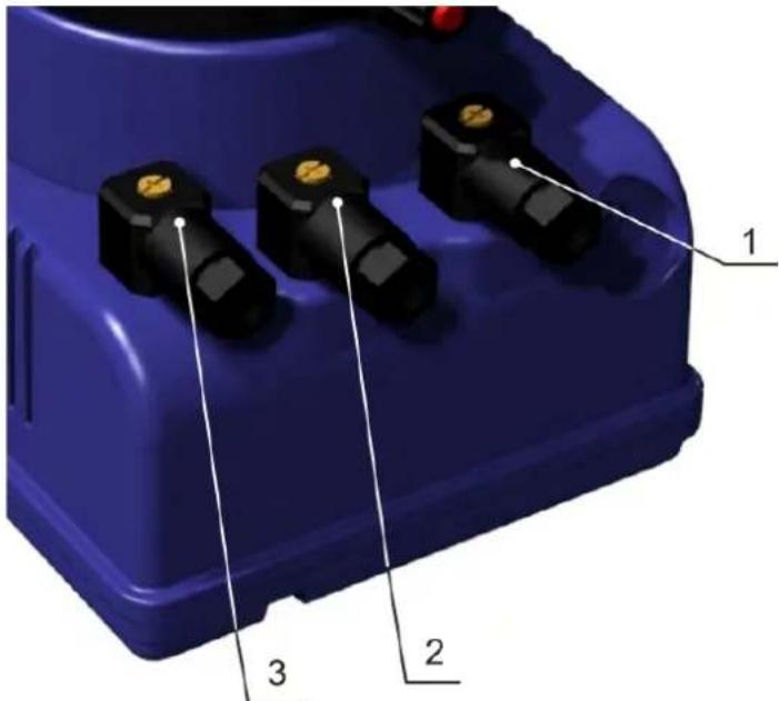
Fig. 10
natural_image
Exploded view diagram of a mechanical assembly with internal components (no text or labels)Fig. 11
Fig. 18
9.0 - POMPA DOSATRICE A MICROCONTROLLORE SERIE EXACTUS VFT/MBB
Fig. 19
1.2 - TRANSPORT ET DEPLACEMENT
DIMENSIONS (Dessin 1)
natural_image
Technical line drawing of a mechanical device with a 143-unit dimension label (no text or symbols on the diagram itself)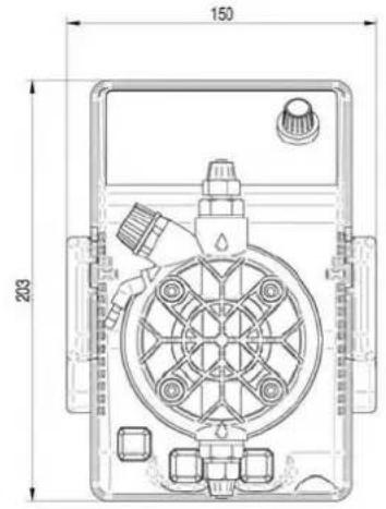
natural_image
Technical line drawing of a mechanical device with no visible text or symbols2.0 - POMPES DOSEUSES MODELES EXACTUS
2.1 - PRINCIPE DE FONCTIONNEMENT
natural_image
Technical line drawing of a mechanical device with tubing and a container (no text or symbols)Dessin 5
flowchart
graph TD
    A["Fluid Inlet"] --> B["Valve"]
    B --> C["Pump"]
    C --> D["Water Tank"]
    D --> E["Control Valve"]
    E --> F["Reactor"]
    F --> G["Return Line"]
Dessin 6
natural_image
Four-step diagram showing a mechanical device with a lever mechanism, no text or symbols presentDessin 7
Dessin 9
3.2 - CABLAGES ET FONCTIONS DU CONNECTEUR SERVICES
Dessin 10
natural_image
Exploded view diagram of a mechanical assembly with multiple components (no text or labels)Dessin 11
Dessin 13
EXACTUS MA/MB
Dessin 14
7.0 - POMPA DOSATRICE A MICROCONTROLLORE SERIE EXACTUS MA/MB
Dessin 18
9.0 - POMPE DOSEUSE ÁMICROCONTROLLEUR EXACTUS VFT/MBB
natural_image
Technical line drawing of a gas collection or gas mixing device with inlet/outlet pipes and control panel (no text or symbols)Abb. 5
flowchart
graph TD
    A["Valve"] --> B["Pump"]
    B --> C["Control Unit"]
    C --> D["Valve"]
    D --> E["Water Tank"]
    style A fill:#f9f,stroke:#333
    style E fill:#bbf,stroke:#333
Abb. 6
natural_image
Four-step diagram showing a mechanical device with a lever and a hand holding a tool, illustrating the process (no text or symbols)Abb. 7
natural_image
Exploded view diagram of a mechanical assembly with multiple components (no text or labels)Abb. 11
Abb. 13
EXACTUS MA/MB
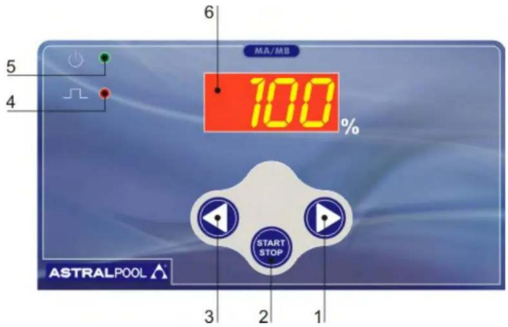
Abb. 14
7.0 - DOSIERPUMPE MIT MIKROCONTROLLER DER SERIE EXACTUS MA/MB
PUMPE EXACTUS CC, DURCHSATZ 10 V/h, DRUCK 5 bar, SIGNAL 4-20 mA.
Abb. 18
9.0 - DOSIERPUMPE MIT MIKROCONTROLLER DER SERIE EXACTUS VFT/MBB
Abb. 19
natural_image
Technical line drawing of a gas washing machine with inlet/outlet pipes and control panel (no text or labels)Fig. 5
flowchart
graph TD
    A["Feed Inlet"] --> B["Pump"]
    B --> C["Valve"]
    C --> D["Tank"]
    D --> E["Water Body"]
    style A fill:#f9f,stroke:#333
    style E fill:#ccf,stroke:#333
Fig. 6
natural_image
Four-step diagram showing a mechanical device with a lever mechanism, no text or symbols presentFig. 7
3.2 - CONEXÃO E FUNÇÕES DOS CONECTORES DE SAÍDA
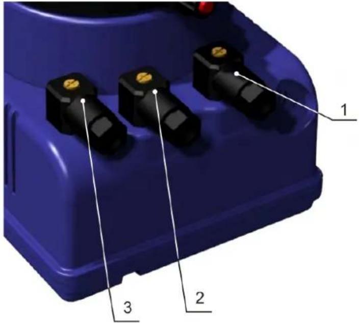
Fig. 10
natural_image
Exploded view diagram of a mechanical assembly with multiple components (no text or labels)Fig. 11
Fig. 13
EXACTUS MA/MB
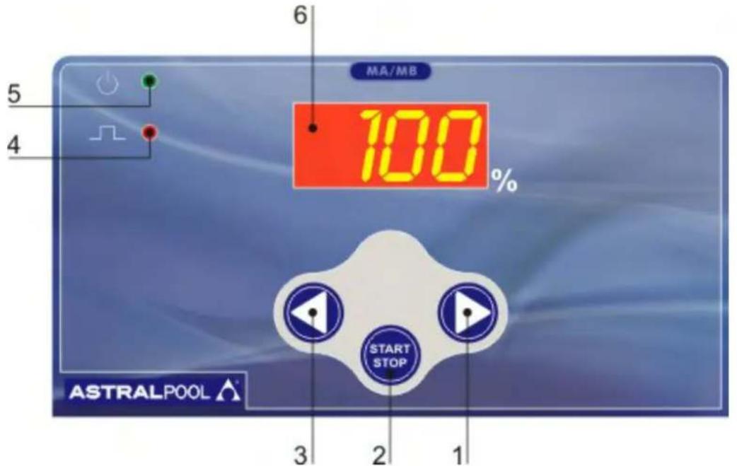
Fig. 14
7.0 - BOMBA DOSADORA MICROPROCESADA SERIE EXACTUS MA/MB
Fig. 19
9.5 - DESCRIÇÃO DAS FUNÇÕES VFT / MBB
PRIMING (100 FLUXO%)
| POS. | ELENCO DEI PARTICOLARI | SPARE PARTS LIST |
| 1 | CASSA | CASING |
| 2 | COPERCHIO POSTERIORE | BACK COVER |
| 3 | SUPPORTO POMPA | PUMP SUPPORT BRAKET |
| 4 | CORPO POMPA | PUMP HEAD |
| 5 | GUARNIZIONE COPERCHIO | BACK COVER GASKET |
| 6 | SERIGRAFIA PANNELLO COMANDI | CONTROL PANEL SERIGRAPHY FILM |
| 7 | GUARNIZIONE DI TENUTA POTENZIOMETRO | POTENTIOMETER GASKET |
| 8 | MANOPOLA REGOLAZIONE IMPULSI | PULSES ADJUSTMENT KNOB |
| 9 | FLANGIA PISTONE | PLUNGER FLANGE |
| 10 | DIAFRAMMA | PTFE DIAPHRAGM |
| 11 | O-RING CORPO POMPA | O-RING PUMP HEAD |
| 12 | VITE 4x8 TS INOX | M4x8 FLATHEAD SCREW |
| 13 | PASSACAVO PG7 + DADO | PG7 CABLE CLAMP |
| 14 | O-RING 10x1,5 | O-RING 10x1,5 |
| 15 | ELETTROMAGNETE | COMPLETE ELECTROMAGNET |
| 16 | VITE 4x16 TC INOX | 4x16 BACK COVER SCREW |
| 17 | VITE 2,9x9,5 | 2,9x9,5 SCREW |
| 18 | SCHEDA ELETTRONICA | PC BOARD |
| 19 | SUPPORTO PER TERMOSTATO | SUPPORT FOR THERMOSTAT |
| 20 | TERMOSTATO | THERMOSTAT |
| 21 | CAVO CON SPINA FASE/NEUTRO CON FASTON FEMMINA | CABLE WITH PHASE/NEUTRAL WIRES AND FEMALE FASTON CONNECTOR |
| 22 | CONNETTORE FEMMINA 4 VIE G4W1F | FEMALE CONNECTOR G4W1F |
| 23 | GUARNIZIONE CONNETTORE | CONNECTOR GASKET |
| 24 | CONNETTORE MASCHIO 4 VIE G4A5M | MALE CONNECTOR G4A5M |
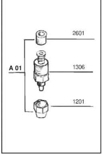
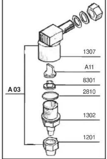
VALVOLE - VALVES
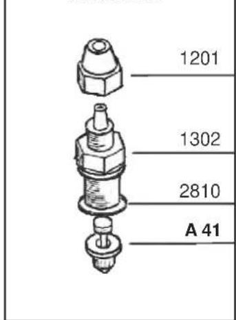
Complete injection valves
VALVOLA INIEZIONE STD. fino a 20 l/h
STD. INJECTION VALVE up to 20 l/h
VALVOLA INIEZIONE 90° fino a 20 l/h
90° INJECTION VALVE up to 20 l/h
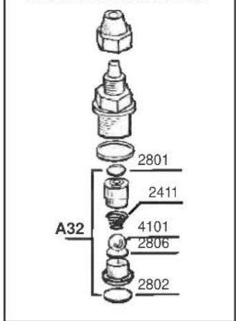
VALVOLA INIEZ. A SFERA fino a 20 l/h
BALL INJECTION VALVE up to 20 l/h
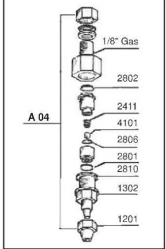
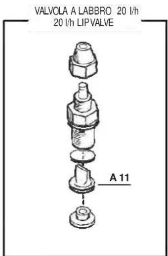
Valvole a labbro - Lip valves
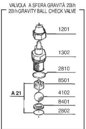
Valvole speciali - Special valves
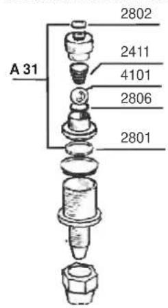
VALVOLA A SFERA ASPIRAZIONE
SUCTION BALL CHECK VALVE
VALVOLA A SFERA MANDATA
DISCHARGE BALL CHECK VALVE
VALVOLA KALRETZ
KALRETZ VALVE
Corpo pompa con spurgo manuale Manual air bleed pump head
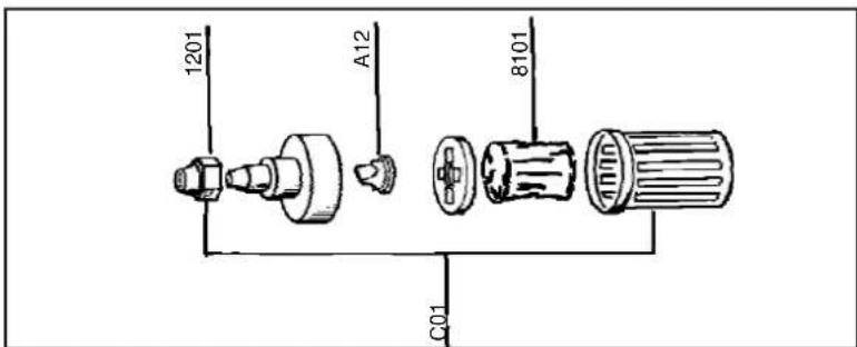
PARTICOLARI DEL CORPO POMPA
1 CORPO POMPA
2 SPINGIVALVOLA
3 VALVOLA A LABBRO
4 DISTANZIALEPER SPURGO
5 O-RING 2062
6 RACCORDOCORPO POMPA
7 TAPPO PERRACCORDO
8 GHIERA FISSATUBO
9 RONDELLA D4 PIANA
10 VITE M4x35 TCINOX BRUGOLA
11 O-RING 2018
12 BUSSOLA 6x5,5 PER CORPO POMPA
13 RACCORDO PER SPURGO
14 O-RING 2012
15 VITE PER SPURGO
16 TAPPO PER SPURGO
17 MANOPOLA PER SPURGO
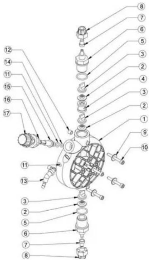
PUMP HEAD DETAILS
1 PUMP HEAD
2 VALVE GUIDE
3 LIP VALVE
4 AIRBLEED SPACER
5 O-RING 2062
6 PUMP HEAD NIPPLE
7 NIPPLE CAP
8 TUBE NUT
9 D4 STAINLESS STEEL WASHER
10 M4x35 STAINLESS STEEL SCREW
11 O-RING 2018
12 6x5,5 PUMP HEAD BUSH
13 AIR BLEED NIPPLE
14 O-RING 2012
15 AIR BLEED SCREW
16 AIR BLEED CAP
17 AIR BLEED KNOB
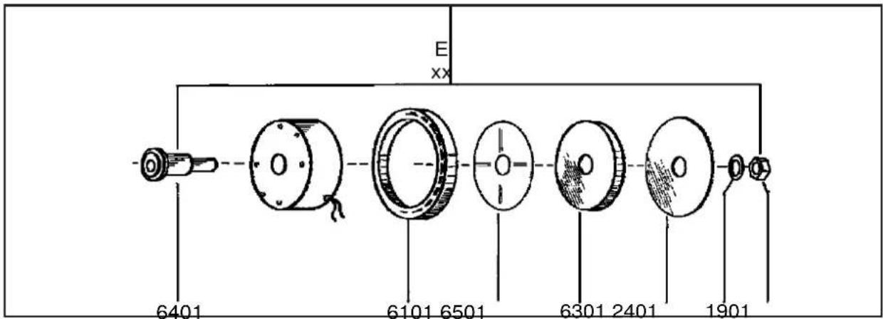
Elettromagnete Completo - Complete Electromagnet
Filtro Std fino a 20 l/h - Std Filter up to 20 l/h
Note:
Note:
Note:


- INDICE
- -NORMAS GENERALES pag. 2
- - BOMBA DOSIFICADORA CON MICROCONTROLADOR SERIE EXACTUS VFT/MBB
- - WARNING:
- - SHIPPING AND TRANSPORTING THE PUMP
- - PROPER USE OF THE PUMP
- - RISKS
- - TOXIC AND/OR DANGEROUS LIQUID DOSAGE
- - ASSEMBLING AND DISMANTLING THE PUMP
- - ASSEMBLY
- - DISMANTLEMENT
- OVERALL DIMENSIONS (Fig. 1)
- - EXACTUS SERIES METERING PUMPS
- - OPERATION
- - COMMON FEATURES
- UPON REQUEST:
- - LIQUID ENDS MATERIALS
- N.B. The sleeve D must not be removed.
- - INJECTION VALVE INSTALLATION DIAGRAM Fig. 9
- - HOW TO OPERATE WHEN DOSING SULPHURIC ACID (MAX 50%)
- EXACTUS MA/AD
- - MANUALLY OPERATED METERING PUMP EXACTUS MA/AD SERIES
- - PUMP CONTROLS (Fig.12)
- - TYPICAL INSTALLATION (Fig.13)
- - ACCESSORIES
- - MICROCONTROLLED DOSING PUMPS EXACTUS MA/MB SERIES
- - PUMP CONTROLS (Fig. 14)
- - TYPICAL INSTALLATION (Fig.15)
- - ACCESSORIES
- - MICROCONTROLLED DOSING PUMPS EXACTUS CC/M SERIES
- - PUMP CONTROLS (Fig. 16)
- - TYPICAL INSTALLATION (Fig.17)
- - ACCESSORIES
- - LEVEL CONTROL (UPON REQUEST)
- - CALIBRATION
- - PARAMETERS SETTING MODE (Fig. 16)
- EXACTUS VFT/MBB
- - MICROCONTROLLED DOSING PUMPS EXACTUS VFT/MBB SERIES
- - PUMP CONTROLS (Fig. 18)
- - TYPICAL INSTALLATION (Fig.19)
- - ACCESSORIES
- - LEVEL CONTROL
- VFT/MBB FEATURE DESCRIPTION
- MANUAL Mode
- 1XN Mode
- 1XN(M) Mode
- 1:N Mode
- PRIMING (100% flow)
- INPUT/OUTPUT EXTERNAL CONNECTIONS (FOR EXTERNAL ACCESSORY)
- SUMMARY OF TYPE OF CONNECTIONS
- - MECHANICAL FAULTS
- ① - THE METERING PUMP GIVES PULSES BUT THE ADDITIVE IS NOT INJECTED
- - ELECTRICAL FAULTS
- - NORME GENERALI 38
- - POMPA DOSATRICE A MICROCONTROLLORE SERIE EXACTUS VFT/MBB
- - TRANSPORT ET DEPLACEMENT
- DIMENSIONS (Dessin 1)
- - POMPES DOSEUSES MODELES EXACTUS
- - PRINCIPE DE FONCTIONNEMENT
- EXACTUS MA/MB
- - POMPA DOSATRICE A MICROCONTROLLORE SERIE EXACTUS MA/MB
- - POMPE DOSEUSE ÁMICROCONTROLLEUR EXACTUS VFT/MBB
- - DOSIERPUMPE MIT MIKROCONTROLLER DER SERIE EXACTUS MA/MB
- - DOSIERPUMPE MIT MIKROCONTROLLER DER SERIE EXACTUS VFT/MBB
- - BOMBA DOSADORA MICROPROCESADA SERIE EXACTUS MA/MB
- - DESCRIÇÃO DAS FUNÇÕES VFT / MBB
- PRIMING (100 FLUXO%)
- VALVOLE - VALVES
- Complete injection valves
- Corpo pompa con spurgo manuale Manual air bleed pump head
- PARTICOLARI DEL CORPO POMPA
- PUMP HEAD DETAILS
- Note:
Brand : ASTRALPOOL
Model : 57893
Category : Water pump