
HPGI50 - Heat pump GRE - Free user manual and instructions
Find the device manual for free HPGI50 GRE in PDF.
| Product type | Swimming pool heat pump |
| Brand / Model | GRE / HPGI50 |
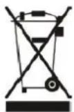
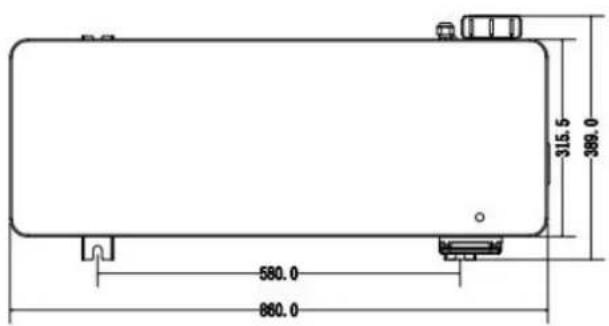
| Dimensions (L x W x H) | 860 x 389 x 586.5 mm |
| Net weight | 56 kg |
| Power supply | 220-240 V ~ 50 Hz / 1 phase |
| Heating power (Air 28°C / Water 28°C) | 10 kW (max) |
| Power consumption | 1.55 kW (max) |
| COP (Coefficient of Performance) | Up to 16 (Air 28°C / Water 28°C) |
| Max pool volume | 55 m³ |
| Recommended water flow | 2.8 m³/h |
| Heat exchanger type | Twisted titanium tube, PVC body |
| Refrigerant | R32, 720 g (GWP = 675) |
| Sound level at 1 m | 40-52 dB(A) |
| Compressor | Inverter |
| Protection rating | IPX4 |
| Main functions | Powerful, Smart and Silent modes; remote control; filtration control |
| Safety | Freeze protection, flow detector, high/low pressure switches, IPM protection, 3 min time delay |
| Maintenance and cleaning | Annual cleaning of evaporator; drain water in winter or if temperature < 0°C; maintenance by qualified technician |
| Spare parts and repairability | Listed parts (evaporator, compressor, fan, electronic boards, etc.); repair by professional |
| Warranty | 2 years parts and labor (according to conditions) |
Frequently Asked Questions - HPGI50 GRE
User questions about HPGI50 GRE
0 question about this device. Answer the ones you know or ask your own.
Ask a new question about this device
Download the instructions for your Heat pump in PDF format for free! Find your manual HPGI50 - GRE and take your electronic device back in hand. On this page are published all the documents necessary for the use of your device. HPGI50 by GRE.
USER MANUAL HPGI50 GRE
natural_image
Exterior view of a black inverter pool heating fan with visible blades and control panel (no text or symbols on the fan itself)inverter pool heating
Refs. HPGI50
HPGI60
HPGI70
HPGI85
Owner's Manual - Manual de Instruccion Manuel d'instructions - Bedienungsanleitung Manuale delle instruzioni - Handleiding met instructies Manual de instruções - Instrukcja obsługi
DISTRIBUTED BY/DISTRIBUIDO POR/DISTRIBUÉ PAR/VERTRIEB DURCH/DISTRIBUITO DA/GEDISTRIBUEERD DOOR/DISTRIBUIDO POR/WYPRODUKOWANY PRZEZ: MANUFACTURAS GRE, S.A. ARITZ BIDEA N° 57 BELAKO INDUSTRIALDEA, APARTADO 69 - 48100 MUNGUIA (VIZCAYA) ESPAÑAN° Reg. Ind. 48-06762
MADE IN CHINA / FABRICADO EN CHINA / FABRIQUÉ AU CHINE / HERGESTELLT IN CHINA / PRODOTTO IN CHINA / GEPRODUCEERD IN CHINA / FABRICADO NA RPC /
WYPRODUKOWANO W CHINACH
INDEX FOR DIFFERENT LANGUAGES
English manual....2\~82
Manual en Español ....83\~110
 | This symbol shows that information is available such as the Operating Manual or Installation Manual. |  | This symbol shows that this appliance uses R32, a low burning velocity refrigerant. |
 | This symbol shows that the Operation Manual should be read carefully. |  | This symbol shows that service personnel should be handling this equipment with reference to the Installation Manual. |
GENERAL WARNINGS
- Failure to respect the warnings may cause serious damage to the pool equipment or cause serious injury, ever death.
- Only a person qualified in the technical fields concerned (electricity, hydraulics or refrigeration) is authorised to carry out maintenance or repair work on the appliance. The qualified technician working on the appliance mus use/wear personal protective equipment (such as safety goggles and protective gloves, etc.) in order to reduce the risk of injury occurring when working on the appliance.
- Before handling the appliance, check that it is switched off and isolated.
- This appliance is not intended for use by individuals (including children, over the age of 8) lacking in experience with impaired physical, sensory or mental capabilities, unless: they receive supervision and are instructed on how to use the appliance by a person responsible for their safety; and if they understand the hazards involved.
- Children must be supervised to ensure that they do not play with the appliance.
- The appliance must be installed according to the manufacturer's instructions and in compliance with local and national standards. The installer is responsible for installing the appliance and for compliance with national installation regulations. Under no circumstances may the manufacturer be held liable in the event of failure to comply with applicable local installation standards.
- For any work other than the simple user maintenance described in this manual, the product should be referred a qualified professional.
- Incorrect installation and/or use may cause serious damage to property or serious injuries (possibly causing death).
- If the appliance suffers a malfunction, do not try to repair it yourself; instead contact a qualified technician.
- Deactivating, eliminating or by-passing any of the safety mechanisms integrated into the appliance shall automatically void the warranty, in addition to the use of spare parts manufactured by unauthorised third-party manufacturers.
- Do not spray insecticide or any other chemical (flammable or non-flammable) in the direction of the appliance, this may damage the body and cause a fire.
- Do not touch the fan or moving parts and do not place objects or your fingers in the vicinity of the moving when the appliance is in operation. Moving parts can cause serious injury or even death.
WARNINGS ASSOCIATED WITH ELECTRICAL APPLIANCES
- The power supply to the appliance must be protected by a dedicated 30 mA Residual Current Device (RCD), complying with the standards and regulations in force in the country in which it is installed.
- Do not use any extension lead when connecting the appliance; connect the appliance directly to a suitable power supply.
• Before carrying out any operations, check that: - The voltage indicated on the appliance information plate corresponds to the mains voltage.
- The power grid must be adapted to the power requirements of the appliance, and is grounded.
- The plug (where applicable) is suitable for the socket.
- Do not disconnect and reconnect the appliance to the power supply when in operation.
- Do not pull on the power cord to disconnect it from the power supply.
- If the power cord is damaged, it must be replaced by the manufacturer, its technician or a qualified person to guarantee safety.
- Do not perform maintenance or servicing operations on the appliance with wet hands or if the appliance is w
- Before connecting the appliance to the power supply, check that the connection unit or socket to which the appliance will be connected is in good condition and shows no signs of damage or rust.
- In stormy weather, disconnect the appliance from the power supply to prevent it from suffering lightning damage. Do not immerse the appliance in water or mud.
WARNINGS CONCERNING APPLIANCES CONTAINING REFRIGERANT R32
• R32 refrigerant is classed under category A2L as mildly flammable.
- Do not release R32 fluid into the atmosphere. These are fluorinated greenhouse gases, covered by the Kyoto Protocol, with a Global Warming Potential (GWP) of 675 (European regulation EU 517/2014).
- The appliance must be stored in a well-ventilated location away from all ignition sources.
• Install the unit outdoors. Do not install the unit indoors or in an enclosed and non-ventilated outdoor location
- Do not use means for accelerating the defrosting or cleaning process other than those recommended by the manufacturer.
- The appliance must be stored in a room without any permanent ignition source (such as open flames, operating gas appliance or operating electric heating).
- Do not perforate or incinerate.
- Please note that R32 refrigerant may give off a certain odour.
- In order to comply with the applicable standards and regulations in terms of the environment and installation, particular French decree No. 2015-1790 and/or European regulation EU 517/2014, a leak test must be performed on the cooling circuit at least once a year. This operation must be carried out by a specialist certified to test cooling appliances.
- Please keep the display controller in a dry area, or well close the insulation cover to protect the display contr from being damaged by humidity.
MAINTENANCE: WARNINGS CONCERNING APPLIANCES CONTAINING R32 REFRIGERANT
- When servicing the appliance, the composition and state of the heat transfer fluid must be checked, as well a absence of any traces of refrigerant.
- During the annual appliance sealing test in accordance with applicable legislation, the high and low pressure switches must be checked to ensure that they are securely fastened to the refrigerant circuit and that they cut the electrical circuit when tripped.
- During maintenance work, ensure there are no traces of corrosion or oil around the cooling components.
- Do not braze or weld the pipe if there is refrigerant inside machine. Please do not charge the gas when in a confined space.
Area check
- Before starting work on systems containing flammable refrigerants, safety checks must be carried out to guarantee a minimal ignition risk.
Work procedure
- The work must be carried out according to a controlled procedure in order to reduce the risks of releasing a flammable gas or vapour while working.
- Before beginning work on the cooling circuit, stop the appliance and wait for a few minutes before fitting the temperature and pressure sensors. Some elements such as the compressor and piping may reach temperatures excess of 100^ C and high pressures with the consequent risk of severe burns.
General work area
- All maintenance staff and other personnel working in the surrounding area must be made aware of the work carried out. Work conducted in enclosed areas must be avoided.
Check for the presence of refrigerant
- The area must be analysed using a suitable refrigerant detector before and during work so that the technician informed of the presence of a potentially toxic or flammable atmosphere. Check that the leak detection equipment used is suitable for use with all refrigerants concerned, i.e. that it does not cause a spark, is corre isolated or is entirely safe.
Check for the presence of a fire extinguisher
- If work must be carried out on the cooling equipment or any part associated therewith at a certain temperatu suitable fire extinguishing means must be within reach. Place a dry chemical fire extinguisher or CO_2 fire extinguisher near the work area.
No source of ignition
- No person carrying out work on a cooling system involving exposing the piping may use any ignition source, which could create a fire or explosion risk. All possible ignition sources, in particular cigarettes, must not enter within sufficient perimeter of the installation, repair, removal or disposal site, in the event that refrigerant could be released into the surrounding space. Before starting the work, the area around the equipment must be examined to check for all fire or ignition risks. "No smoking" signs must be displayed.
Area ventilation
- Before accessing the unit in any manner whatsoever with the intention of performing any maintenance task, check that the area is open and well-ventilated. Suitable ventilation must be provided throughout the maintenance task to allow any refrigerant that could be released into the atmosphere to be safely dispersed.
Refrigeration equipment check
- The manufacturer's recommendations in terms of care and maintenance must always be complied with. When replacing electric components, check that components used are of the same type and category as those recommended/approved by the manufacturer. When in doubt, contact the manufacturer's technical department for assistance.
-
The following checks must be applied to installations using flammable refrigerants:
-
the markings on the equipment must remain visible and legible; any illegible markings or signs must be rectified;
- the hoses or components of the cooling circuit are installed in a position where they are unlikely to be exposed to any substance capable of corroding the components containing refrigerant, unless the components are made from materials that are typically corrosion-proof or correctly protected from such corrosion.
Electric component check
- The repair and maintenance of electric components must include initial safety checks and component inspection procedures. If a defect capable of jeopardising safety arises, no power supply must be connected to the circuit until the problem has been completely resolved. If the defect cannot be rectified immediately and if maintain work must continue, an appropriate temporary solution must be found. This must be reported to the equipme owner so that all persons concerned are made aware.
- The repair and maintenance of electric components must include the following initial safety checks:
– the capacitors are discharged: this must be carried out safely to prevent all risks of ignition;
– no electric component or live wiring is exposed while charging, overhauling or draining the system;
- the system must be grounded at all times.
Repair of insulated components
- When repairing insulated components, all power sources must be disconnected from the equipment on which it work is being carried out before removing the insulating cover, etc. If the equipment must be powered during maintenance work, a leak detector must continuously monitor for leaks at the most critical point in order to report any potentially hazardous situation.
- Particular attention must be paid to the following points to ensure that, when performing work on the electric components, the housing is not altered to the point of affecting the protection rating. This includes damaged wires, an excessive number of connections, terminals that do not comply with the original specifications, damaged seals, incorrect installation of the cable glands, etc.
• Make sure that the appliance is properly fixed. - Make sure that the seals or insulating materials are not deteriorated to the point that they no longer prevent flammable atmosphere from penetrating the circuit. Spare parts must be compliant with the manufacturer's specifications.
Repair of intrinsically safe components
- Do not apply any permanent electric capacitance or induction charge to the circuit without checking that it do not exceed the allowed voltage and intensity for the equipment being used.
- Typically safe components are the only types on which work can be carried out in the presence of a flammab atmosphere when live. The test appliance must fall under a suitable classification.
- Only replace components with parts specified by the manufacturer. Other parts could cause the refrigerant to leak and ignite in the atmosphere.
Wiring
- Check that the wiring shows no signs of wear, corrosion, excessive pressure, vibration, cutting edges or any ot detrimental environmental effect. The check must also take into account the effects of ageing or continuous vibrations caused by sources such as compressors or fans.
Detection of flammable refrigerant
- Under no circumstances must potential ignition sources be used to search for or detect refrigerant leaks. A ha torch (or any other detector using a naked flame) must not be used.
- The following leak detection methods are considered to be acceptable for all cooling systems.
- Electronic leak detectors can be used to detect refrigerant leaks; however, in the case of flammable refrigerant the sensitivity level may not be suitable or recalibration may be necessary. (The detection equipment must be calibrated in an area devoid of refrigerant). Check that the detector is not a potential ignition source and is appropriate for the refrigerant used. The leak detection equipment must be adjusted to a percentage of the refrigerant's LFL and must be calibrated according to the refrigerant used. The appropriate gas percentage (25% at most) must be confirmed.
- Leak detection fluids are also suited for use with most refrigerants, however the use of detergents containing chlorine must be avoided since it could react with the refrigerant and cause corrosion to the copper piping.
- If a leak is suspected, all naked flames must be removed/extinguished.
- If a refrigerant leak is detected and requires soldering, the entire quantity of refrigerant must be removed from the system or isolated (by way of shut-off valves) in part of the system located away from the leak.
Removal and discharge
- When accessing the cooling circuit to carry out repairs, or for any other reason, conventional procedures must employed. However, for flammable refrigerants, the recommendations must be complied with in order to take account of the product's flammability. The following procedure must be followed:
- remove the refrigerant;
• purge the circuit with an inert gas (optional for A2L);
• drain (optional for A2L);
• purge with an inert gas (optional for A2L);
- open the circuit by cutting or soldering.
- The refrigerant charge must be recovered in suitable recovery cylinders. For appliances containing flammable refrigerants other than A2L refrigerants, the system must be bled with nitrogen devoid of oxygen to make the appliance suitable for receiving flammable refrigerants. You may need to repeat this process several times. Compressed air or oxygen must not be used to purge cooling systems.
Loading procedures
- Check that the vacuum pump outlet is not located in the vicinity of any potential ignition source and that ventilation is provided.
- In addition to conventional charging procedures, the following requirements apply.
- Check that there is no possibility of cross-contamination between the different refrigerants when using charging equipment. Hoses or lines must be as short as possible to reduce the quantity of refrigerant contained therein
- Cylinders must be kept in an appropriate position, in accordance with the instructions.
- Check that the cooling system is grounded before charging the system with refrigerant.
- Label the system once charging is complete (if this is not already the case).
- Pay close attention to not overfilling the cooling system.
- Before recharging the system, carry out a pressure test using a suitable purge gas. The system must be examined to make sure there are no leaks after the charging operation and before commissioning. A follow-up leak test must be carried out before leaving the site.
Dismantling
- Before dismantling, the technician must familiarise himself/herself with the equipment and its specifications. We highly recommend carefully recovering all refrigerants. Before this, oil and refrigerant samples must be taken if analyses are to be carried out before any other use of the recovered refrigerant. Check for the presence of a power supply before starting work.
- Familiarise yourself with the equipment and how it operates.
- Electrically isolate the system.
- Before starting work, check the following points:
– mechanical handling equipment is available if needed to handle the refrigerant cylinders;
– all personal protective equipment is available and used correctly;
– the recovery process is followed at all times by a cognizant person;
– the recovery cylinders and equipment comply with the relevant standards.
4. Drain the cooling system where possible.
5. If a vacuum cannot be created, install a manifold in order to be able to remove the refrigerant from various locations within the system.
6. Make sure that the cylinder is located on the scales before starting recovery operations.
7. Start the recovery unit and operate as per its instructions.
8. Do not overfill the cylinders (no more than 80% of the volume must be filled with liquid).
9. Do not exceed the maximum working pressure of the cylinder, even temporarily.
10. When the cylinders have been filled correctly and the process is complete, check that the cylinders and the equipment are quickly removed from the site and that the alternative shut-off valves on the equipment are closed.
11. The recovered refrigerant must not be charged in another cooling system, unless it has been cleaned and inspected.
TROUBLESHOOTING
- All brazing must be carried out by qualified brazers.
- Replacement pipes must always be made of copper in compliance with standard NF EN 12735-1.
- Leak detection; pressure test:
– never use oxygen or dry air, risk of fire or explosion,
- use dry nitrogen or the mixture of nitrogen and refrigerant indicated on the information plate,
- the test pressure for both the high and low pressure circuits must not exceed 42 bar in cases where the appliance is equipped with the optional pressure gauge.
- The high pressure circuit pipes are made of copper and have a diameter equal to or greater than 1"5/8. A certificate as indicated in §2.1 in compliance with standard NF EN 10204 must be requested from the supplier filed in the installation's technical file.
- Technical data relative to the safety requirements of the various applicable directives are indicated on the information plate. All this information must be recorded in the appliance's installation manual, which must be kept in its technical file: model, code, serial number, maximum and minimum OT, OP, year of manufacture, CE marking, manufacturer's address, refrigerant and weight, electrical parameters, thermo-dynamic and acoustic performance.
LABELLING
- The equipment must be labelled so as to specify that it is out of order and that the refrigerant has been dra
• The label must be dated and signed. - For appliances containing a flammable refrigerant, check that labels are placed on the equipment stating that it contains a flammable refrigerant.
RECOVERY
- When draining the refrigerant for maintenance or decommissioning, best practices should be followed in order safely drain all of the refrigerant.
- When transferring refrigerant to a cylinder, make sure that you use a recovery cylinder that is compatible with refrigerant. Make sure that the correct number of cylinders are provided for recovering all of the refrigerant. A cylinders used must be intended for the recovery of refrigerant and must be labelled for this specific refrigerator. The cylinders must be equipped with a vacuum valve and a stop gate in good working order. Empty collection cylinders are drained and, where possible, cooled before recovery.
- The recovery equipment must be in good working order, the instructions for using the equipment must be with reach and the equipment must be compatible for use with the refrigerant concerned, including, where appropriate, a flammable refrigerant. Moreover, a set of calibrated scales must be available and in good working order. The pipework must be complete, have no leaks or disconnected connectors, and must be in good condition. Before using the recovery unit, check that it is in good working order, that it has been well maintained and the associated electric components are sealed so as to prevent any risk of fire in the event of refrigerant being released. If you have any doubts, contact the manufacturer.
- The recovered refrigerant must be sent to the refrigerant supplier in its recovery cylinder with a waste transfer note. Do not mix different refrigerants in the recovery units, and in particular in the cylinders.
- If the compressor has been removed or if oil from the compressor has been drained, check that the refrigerant has been completely removed to prevent it from mixing with the lubricant. The draining process must be carried out before returning the compressor to the supplier. Only the electric heater of the compressor body can be carried to accelerate this process. This operation can be carried out safely once all liquids within the system have been drained.
RECYCLING
This symbol is required by the European directive DEEE 2012/19/EU (directive on waste electrical and electronic equipment) and means that your appliance must be thrown into a normal bin. It will be selectively collected for the purpose of recycling or transformation. If it contains any substances that may be harmful to environment, these will be eliminated or neutralised. Contact your retailer for recycling information.

ADVERTENCIAS
ALGEMENE WAARSCHUWINGEN
WAARSCHUWINGEN MET BETREKKING TOT ELEKTRISCHE APPARATEN
Swimming Pool Heat Pump User and Service manual
INDEX
- Specifications
- Dimension
- Installation and connection
- Accessories
- Electrical Wiring
- Display Controller Operation
- Troubleshooting
- Exploded Diagram
- Maintenance
Thank you for using Gre swimming pool heat pump for your pool heating, it will heat your pool water and keep the constant temperature when the air ambient temperature is at +7 to 43°C

ATTENTION: This manual includes all the necessary information with the use and the installation of
heat pump.
The installer must read the manual and attentively follow the instructions in implementation and maintenance. Please keep and pass on this manual for later throughout the appliance's service life.
The installer is responsible for the installation of the product and should follow all the instructions of the manufacturer and the regulations in application. Incorrect installation against the manual implies the exclusive the entire guarantee.
The manufacturer declines any responsibility for the damage caused with the people, objects and of the er to the installation that disobey the manual guideline. Any use that is without conformity at the origin of it manufacturing will be regarded as dangerous.
1. Specifications
Technical data pool heat pumps
| Model | HPGI50 | HPGI60 | HPGI70 | HPGI85 | |
| Code | 74162 | 74163 | 74164 | 74165 | |
| * Performance at Air 28°C, Water 28°C, Humidity 80% | |||||
| Heating capacity | kW | 10-2.3 | 12-2.9 | 15-3.2 | 17-3.8 |
| Power consumption | kW | 1.55-0.14 | 1.77-0.18 | 2.26-0.2 | 2.67-0.23 |
| C.O.P. | 16-6.5 | 16-6.8 | 16-6.6 | 16-6.4 | |
| * Performance at Air 15°C, Water 26°C, Humidity 70% | |||||
| Heating capacity | kW | 7-1.9 | 8.5-2 | 10-2.2 | 12-3 |
| Power consumption | kW | 1.43-0.27 | 1.72-0.28 | 2.07-0.31 | 2.43-0.42 |
| C.O.P. | 7.1-4.9 | 7.2-4.9 | 7.2-4.8 | 7.2-4.9 | |
| * General data | |||||
| Compressor type | Inverter Compressor | ||||
| Voltage | V | 220~240V / 50Hz /1PH | |||
| Rated current | A | 6.9 | 7.9 | 10.0 | 11.8 |
| Minimum fuse | A | 10 | 12 | 15 | 18 |
| Maximum pool volume** | m3 | <55 | <70 | <80 | < 95 |
| Advised water flux | m3/h | 2.8 | 3.7 | 4.0 | 4.6 |
| Water pressure drop | Kpa | 12 | 14 | 15 | 15 |
| Heat exchanger | Twist-titanium tube in PVC | ||||
| Water connection | mm | 50 | |||
| Ventilation type | Horizontal | ||||
| Protection rating | IPX4 | ||||
| Max Pressure-suction and discharge side | MPa | 4.2 | |||
| Noise level(10m) | dB(A) | 22-34 | 23-35 | 23-37 | 24-37 |
| Noise level(1m) | dB(A) | 40-52 | 40-52 | 40-54 | 41-54 |
| Refrigerant | R32 | ||||
| Refrigerant quantity | g | 720 | 550 | 750 | 850 |
| CO2 equivalent | Tonne | 0.49 | 0.37 | 0.51 | 0.57 |
| Net weight | kg | 56 | 68 | 73 | 78 |
| Gross weight | kg | 68 | 73 | 78 | 83 |
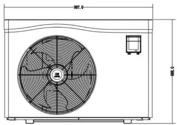
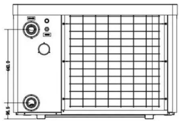
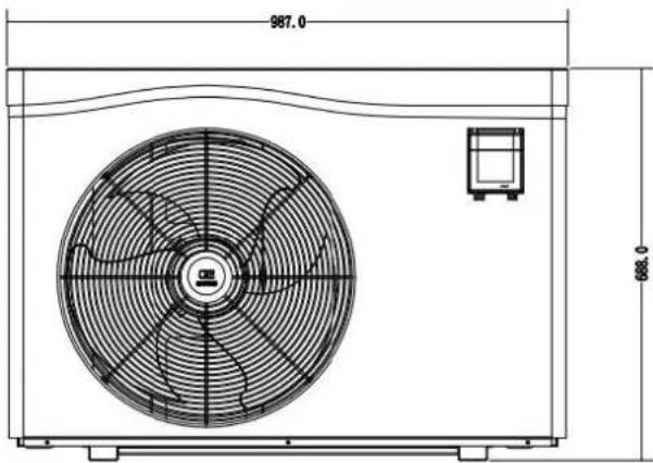
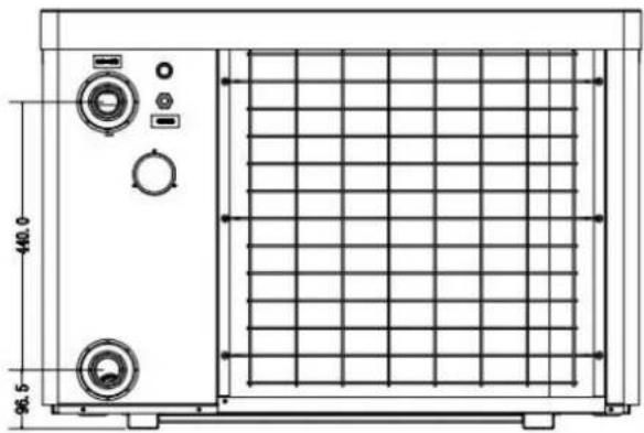
| Net dimension | mm | 860*389*586.5 | 987*400.5*688 | ||
| Packing dimension | mm | 890*420*625 | 1015*435*713 | ||
* Above data is subject to update without prior notice.
**Check our packaging or website for more details.
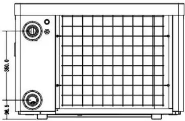
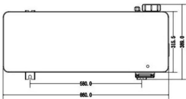
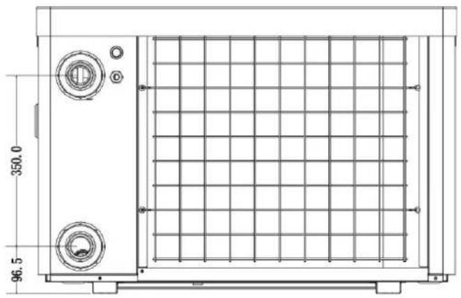
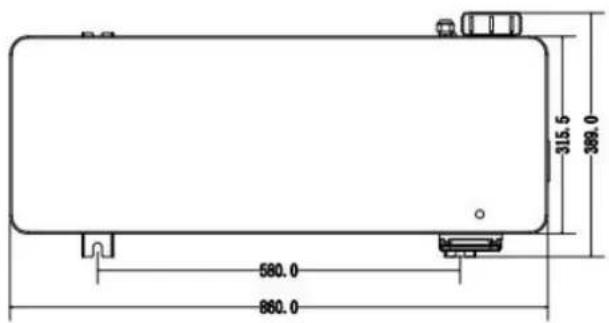
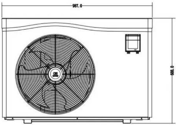
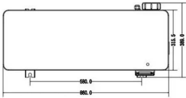
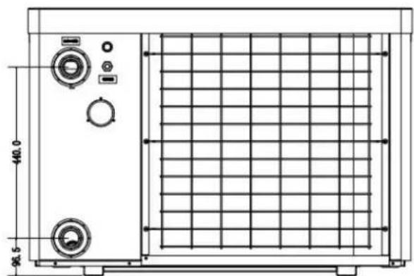
2. Dimension (mm)
Model: HPGI50
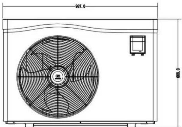
Model: HPGI60/70/85

natural_image
Technical line drawing of a rectangular industrial or laboratory equipment unit with control panel and side gauges (no text or symbols)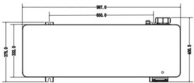
3. Installation and connection
3.1 Notes
The factory supplies only the heat pump. All other components, including a bypass if necessary, must be provided by the user or the installer.
Attention:
Please observe the following rules when installing the heat pump:
- Any addition of chemicals must take place in the piping located downstream from the heat pump.
- Install a bypass if the water flow from the swimming pool pump is more than 20% greater than the allowable flow through the heat exchanger of the heat pump.
- Always place the heat pump on a solid foundation and use the included rubber mounts to avoid vibration and noise.
- Always hold the heat pump upright. If the unit has been held at an angle, wait at least 24 hours before starting the heat pump.3.2 Heat pump location
3.2 Heat pump placement
The unit will work properly in any desired location as long as the following three items are present:
1. Fresh air - 2. Electricity - 3. Swimming pool filters
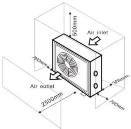
The unit may be installed in virtually any outdoor location as long as the specified minimum distances to other objects are maintained (see drawing below). Please consult your installer for installation with an indoor pool. Installation in a windy location does not present any problem at all, unlike the situation with a gas heater (including pilot flame problems).
ATTENTION: Never install the unit in a closed room with a limited air volume in which the air expelled from the unit will be reused, or close to shrubbery that could block the air inlet. Such locations impair the continuous supply of fresh air, resulting in reduced efficiency and possibly preventing sufficient heat output.
See the drawing below for minimum dimensions.
3.3 Distance from your swimming pool
The heat pump is normally installed within a perimeter area extending 7.5 m from the swimming pool. The greater the distance from the pool, the greater the heat loss in the pipes. As the pipes are mostly underground, the heat loss is low for distances up to 30 m (15 m from and to the pump; 30 m in total) unless the ground is wet or the groundwater level is high. A rough estimate of the heat loss per 30 m is 0.6 kWh (2,000 BTU) for every 5 °C difference between the water temperature in the pool and the temperature of the soil surrounding the pipe. This increases the operating time by 3% to 5%.
3.4 Check-valve installation
Note: If automatic dosing equipment for chlorine and acidity (pH) is used, it is essential to protect the heat pump against excessively high chemical concentrations which may corrode the heat exchanger. For this reason, equipment of this sort must always be fitted in the piping on the downstream side of the heat pump, and it is recommended to install a check-valve to prevent reverse flow in the absence of water circulation.
Damage to the heat pump caused by failure to observe this instruction is not covered by the warranty.
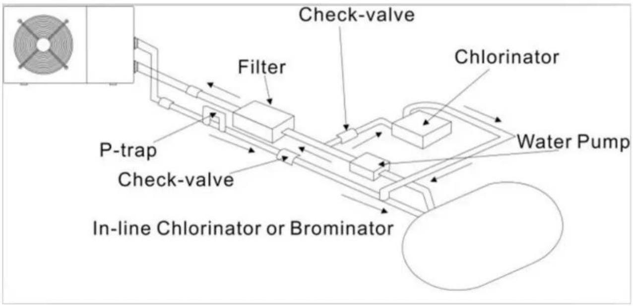
flowchart
graph TD
    A["In-line Chlorinator or Brominator"] --> B["P-trap"]
    B --> C["Check-valve"]
    C --> D["Filter"]
    D --> E["Check-valve"]
    E --> F["Chlorinator"]
    F --> G["Water Pump"]
    style A fill:#f9f,stroke:#333
    style G fill:#ccf,stroke:#333
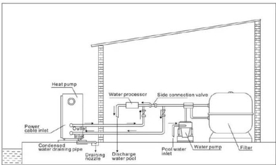
3.5 Typical arrangement
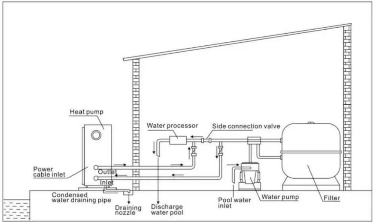
Note: This arrangement is only an illustrative example.
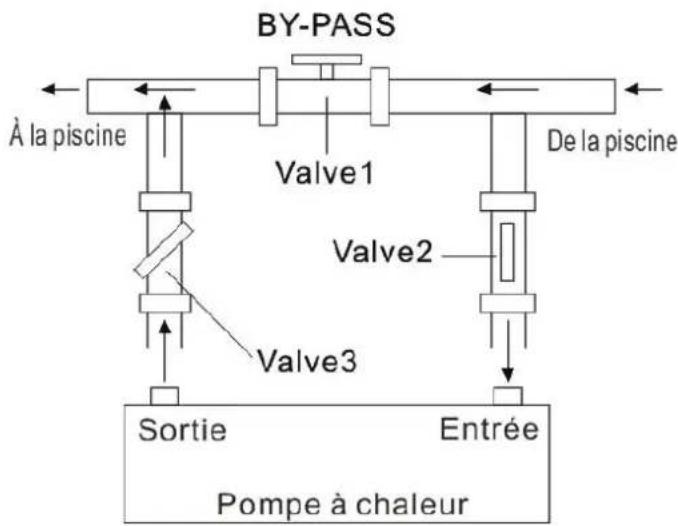
3.6 Adjusting the bypass
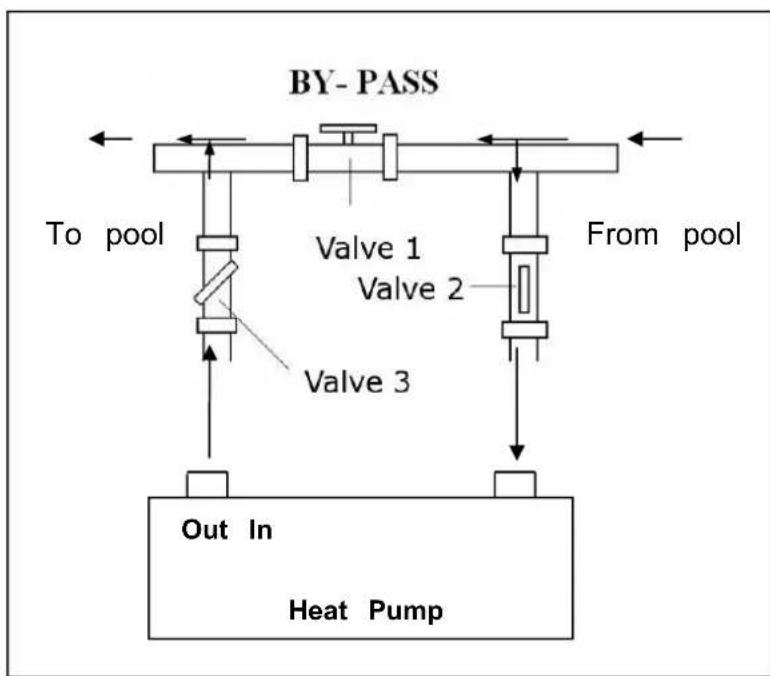
flowchart
graph TD
    A["To pool"] --> B["Valve 1"]
    B --> C["Valve 2"]
    C --> D["Valve 3"]
    D --> E["Out In Heat Pump"]
    F["From pool"] --> G["After BY-PASS"]
    style A fill:#f9f,stroke:#333
    style F fill:#f9f,stroke:#333
    style G fill:#ccf,stroke:#333
Use the following procedure to adjust the bypass:
- Valve 1 wide open. Valve 2 & valve 3 closed.
2.Slowly open valve 2 & valve 3 half, then close the valve 1 slow to increase the water flow to valve & valve 3.
- If it shows 'ON' or 'EE3' on display, it means the water flow heat pump is not enough, then need adjust the valves to increase the water flow through the heat pump.
How to get the optimum water flow:
Please turn on the heat pump under heating function, firstly close the by-pass then open it slowly to start the heat pump (the machine can't start running when the water flow is insufficient).
Continue to adjust the by-pass, at the meantime to check the Inlet water temp. & Outlet water temp., it will be optimum when the difference is around 2 degree.
3.7 Electrical connection
Note: Although the heat pump is electrically isolated from the rest of the swimming pool system, this only prevents the flow of electrical current to or from the water in the pool. Earthing is still required for protection against short-circuits inside the unit. Always provide a good earth connection.
Warning: Before any work inside the appliance, you must cut the appliance's electricity supply as there is a risk of electric shock which may cause material damage, serious injury or even death.
- Incorrectly tightened terminals may cause the terminal box to heat up, which can invalidate the warranty.
- Only a qualified and experienced technician is authorised to carry out cabling work within the appliance or to replace the power cord.
Before connecting the unit, verify that the supply voltage matches the operating voltage of the heat pump.
It is recommended to connect the heat pump to a circuit with its own fuse or circuit breaker (slow type; curve D) and to use adequate wiring.
Connect the electrical wires to the terminal block marked 'POWER SUPPLY'.
A second terminal block marked 'WATER PUMP' is located next to the first one. The filter pump switch(12V) can be connected to the second terminal block here. This allows the filter pump operation to be controlled by the heat pump or the extra dry contact.
3.8 Initial operation
Note: In order to heat the water in the pool (or hot tub), the filter pump must be running to cause the water to circulate through the heat pump. The heat pump will not start up if the water is not circulating.
After all connections have been made and checked, carry out the following procedure:
- Switch on the filter pump. Check for leaks and verify that water is flowing from and to the swimming pool.
- Connect power to the heat pump and press the On/Off button on the electronic control panel. The unit will start up after the time delay expires.
- After a few minutes, check whether the air blowing out of the unit is cooler.
- When turn off the filter pump, the unit should also turn off automatically, if not, then adjust the flow switch.
Depending on the initial temperature of the water in the swimming pool and the air temperature, it may take several days to heat the water to the desired temperature. A good swimming pool cover can dramatically reduce the required length of time.
Water Flow Switch:
It is equipped with a flow switch for protecting the HP unit running with adequate water flow rate. It will turn on the pool pump runs and shut it off when the pump shuts off. If the pool water level higher than 1 m above or below the heat pump's automatic adjustment knob, your dealer may need to adjust its initial startup.
Time delay - The heat pump has a built-in 3-minute start-up delay to protect the circuitry and avoid excessive contact wear. The unit will restart automatically after this time delay expires. Even a brief power interruption will trigger this time delay and prevent the unit from restarting immediately. Additional power interruptions during this delay period do not affect the 3-minute duration of the delay.
3.9 Condensation
The air drawn into the heat pump is strongly cooled by the operation of the heat pump for heating the pool water which may cause condensation on the fins of the evaporator. The amount of condensation may be as much as several litres per hour at high relative humidity. This is sometimes mistakenly regarded as a water leak.
3.10 Operating modes for optimal use
- POWERFUL: Used primarily at the beginning of the season because this mode allows very rapid temperature rise - SMART: The heat pump has completed its primary task, in this mode; the heat pump is in a position to maintain the pool water in an energy efficient manner. By automatically adjusting speed of compressor and fan the heat pump delivers a better return.
- SILENT: In the summer months when the heat output is minimal required, the heat pump in this mode is even more profitable. Added benefit; when the heat pump heats. It goes with minimal noise load.
4. Accessories
4.1 Accessories list
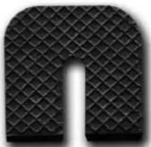 Anti-vibration base, 4 pcs Anti-vibration base, 4 pcs | 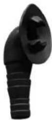 Draining jet, 2 pcs Draining jet, 2 pcs | 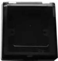 Waterproof box, 1 pc Waterproof box, 1 pc |
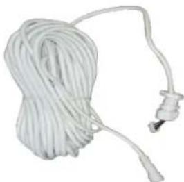 10M Signal wire, 1 pc 10M Signal wire, 1 pc | 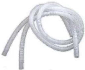 Water drainage pipes, 2 pcs Water drainage pipes, 2 pcs |  Winter cover, 1 pcs Winter cover, 1 pcs |
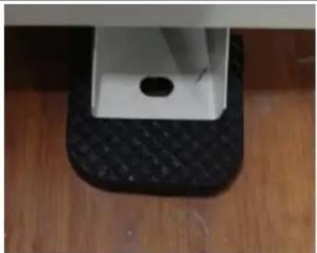
4.2 Accessories Installation
natural_image
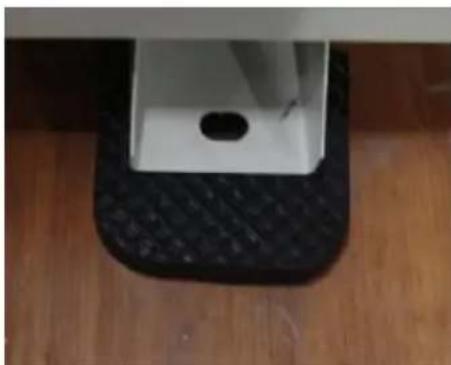
Close-up of a white rectangular object placed on a black textured base, placed on a wooden floor (no text or symbols visible)Anti-vibration bases
- Take out 4 Anti-vibration bases
- Put them one by one on the botton machine like the picture.
natural_image
Close-up of a black pipe fitting attached to a wooden surface, with a mesh fence in the background (no text or symbols visible)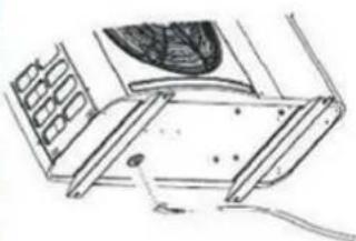
natural_image
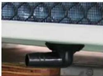
Technical line drawing of a mechanical assembly with no visible text or symbolsDraining jet
- Install the draining jet under the bottom panel
- Connect with a water pipe to drain the water.
Note: Lift the heat pump to install the jet. Never overturn the heat pump, it could damage the compressor.
natural_image
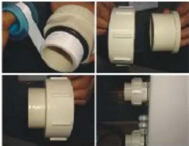
Four-panel photo showing hands assembling a white PVC pipe fitting, with no visible text or symbols.Water Inlet & outlet junction
- Use the pipe tape to connect the water Inlet & outlet junction onto the heat pump
- Install the two joints like the picture shows
- Screw them onto the water Inlet & outlet junction
natural_image
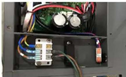
Interior view of an electronic control panel with visible wiring and components (no text or symbols)Cable wiring
- Open the cover of the electric box
- Fix the power supply wire on joints E
natural_image
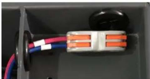
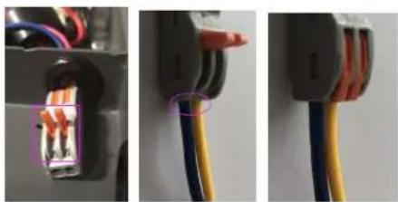
Close-up of an electrical connector with orange and blue wires, no visible text or symbolsWater pump wiring (Dry contact)
- Open the cover of the electric box
- With the connector 1 and 2 you can pilot the water filtration through the timer of the filtration (dry contact)
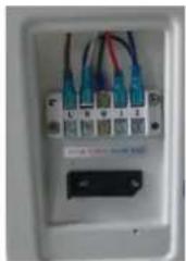
4.3 Connection to the filtration pump
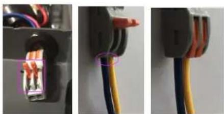
natural_image
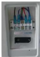
Close-up of three electrical connectors with wires and colored wires, no visible text or symbolsPhoto 1 Photo 2 Photo 3
- Open the button upwards as (Photo 1)
- Attach the dry contact wiring through the two holes as (Photo 2 & Photo 4)
- Press the button and tighten the wiring as (Photo 3)
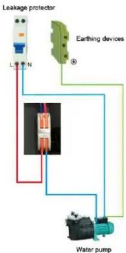
flowchart
graph TD
    A["Leakage protector"] --> B["L"]
    A --> C["N"]
    D["Earthing devices"] --> E["④"]
    F["Water pump"] --> G["Red line"]
    F --> H["Blue line"]
    F --> I["Green line"]
    F --> J["Teal line"]
Photo 4
5. Electrical Wiring
5.1 SWIMMING POOL HEAT PUMP WIRING DIADRAM
HPGI50, HPGI60, HPGI70, HPGI85
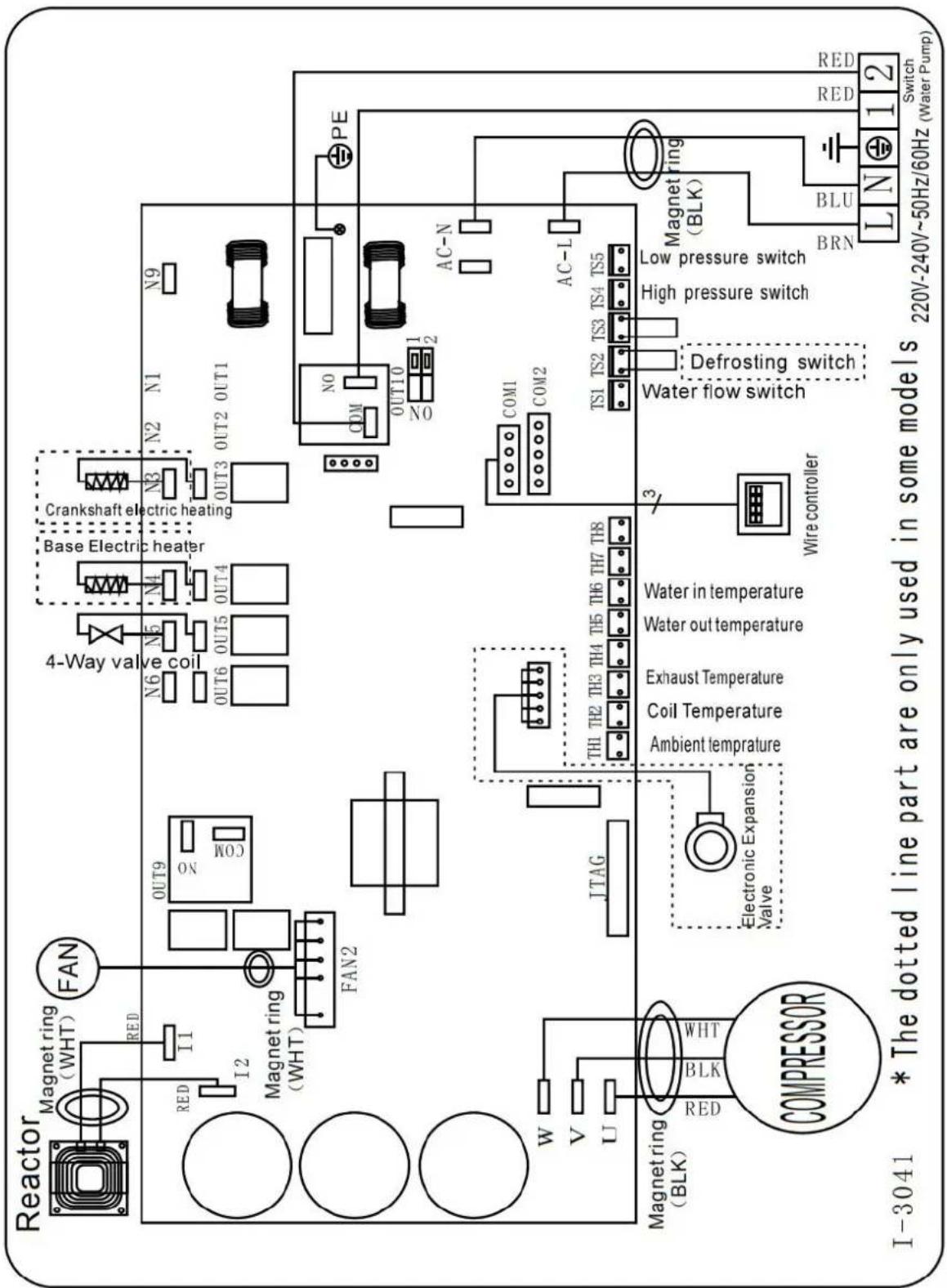
flowchart
graph TD
    A["Reactor"] --> B["Magnet ring (WHT)"]
    B --> C["FAN"]
    C --> D["OUT9"]
    D --> E["4-Way valve coil"]
    E --> F["N6 N5 N4"]
    F --> G["Base Electric heater"]
    G --> H["Crankshaft electric heating"]
    H --> I["N3 N2 N1 N9"]
    I --> J["OUT3 OUT2 OUT1"]
    J --> K["PE"]
    K --> L["AC-N"]
    L --> M["COM1 COM2"]
    M --> N["AC-L"]
    N --> O["Magnet ring (BLK)"]
    O --> P["BRN BLU"]
    P --> Q["Switch (Water Pump)"]
    Q --> R["Red RED 220V-240V~50Hz/60Hz"]
    R --> S["Low pressure switch"]
    S --> T["High pressure switch"]
    T --> U["Defrosting switch"]
    U --> V["Water flow switch"]
    V --> W["Wire controller"]
    W --> X["Water in temperature"]
    X --> Y["Ambient temperature"]
    Y --> Z["Th1 TH2 TH3 TH4 TH5 TH6 TH7 TH8"]
    Z --> AA["Electronic Expansion Valve"]
    AA --> AB["Magnet ring (BLK)"]
    AB --> AC["COMPRESSOR"]
    AC --> AD["W V U"]
    AD --> AE["Magnet ring (WHT)"]
    AE --> AF["I-3041 * The dotted line part are only used in some models"]
NOTE:
(1)Above electrical wiring diagram only for your reference, please subject machine posted the wiring diagram.
(2)The swimming pool heat pump must be connected ground wire well, although the unit heat exchanger is electrically isolated from the rest of the unit .Grounding the unit is still required to protect you against short circuits inside the unit .Bonding is also required.
(3)It is recommended that your pool filtration pump and your heat pump are wired independently.
Wiring your pool pump into the heat pump will result in your filtration being switched off once the pool water has reached temperature.
Only wire the pool pump through the heat pump if you have a pool pump for heating only that is independent to ur pool filtration system.
Disconnect: A disconnect means (circuit breaker, fused or un-fused switch) should be located within sight of and readily accessible from the unit. This is common practice on commercial and residential heat pumps. It prevents remotely-energizing unattended equipment and permits turning off power at the unit while the unit is being serviced.
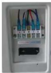
5.2 Installation of the remote control
Photo(1) Photo(2) Photo(3) Photo(4) Photo(5)
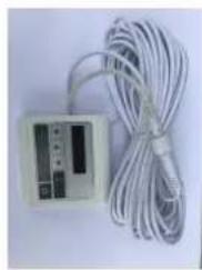
natural_image
White electronic device with coiled cable and indicator lights (no visible text or symbols)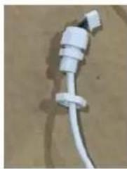
natural_image
Close-up of a white plastic electrical plug with a coiled cable, lying on a plain surface (no text or symbols visible)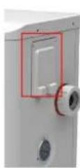
natural_image
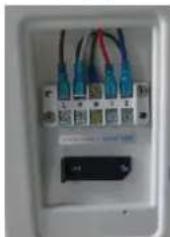
Close-up of a white electrical outlet with multiple blue and red cables connected to a grid of connectors (no visible text or symbols)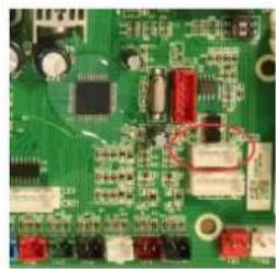
natural_image
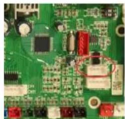
Close-up of a green printed circuit board with various electronic components (no visible text or symbols)- The side with plug connects with the control panel (photo1)
- The other side of the signal wire. (photo2)
- Open the wiring panel and put the side without plug through the electrical box. (photo3,4)
- Insert the wiring into the disignated position (code:COM 1 or COM-L) on the PC board. (photo5)
6. Display Controller Operation
6.1 The buttons of LED wire controller
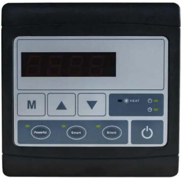
6.2 The keys and their operations
NOTE: Every time, when the heat pump connects to the power, the LED display shows a code for 3 seconds which indicates the heat pump model.
6.2.1 button
Press to start the heat pump unit, the LED display shows the desired water temperature for 5 seconds, then shows the inlet water temperature and the operation mode.
Press to stop the heat pump unit and show "OFF"
Notice : During the parameter checking and setting, press the to quick-exit and save the current setting .
Press again to turn on/off the machine.
6.2.2 and button
Clock/unclock the display:
Hold and for 5 seconds to lock/Unlock the display.
Water temperature setting :
Press

or

to set the water temperature directly.
Water temp. setting range in Heating mode :6-41°C,
6.2.3 button
Parameter checking :
Press first, then press to check the "User parameter from d0 to d11
| Code | Condition | Scope | Remark |
| d0 | IPM mould temperature | 0-120°C | Real testing value |
| d1 | Inlet water temp. | -9°C~99°C | Real testing value |
| d2 | Outlet water temp. | -9°C~99°C | Real testing value |
| d3 | Ambient temp. | -30°C~70°C | Real testing value |
| d4 | Frequency limitation code | 0,1,2,4,8,16 | Real testing value |
| d5 | Piping temp. | -30°C~70°C | Real testing value |
| d6 | Gas exhaust temperature | 0°C~C5°C (125°C) | Real testing value |
| d7 | Step of EEV | 0~99 | N*5 |
| d8 | Compressor running frequency | 0~99Hz | Real testing value |
| d9 | Compressor current | 0~30A | Real testing value |
| d10 | Current fan speed | 0-1200 (rpm) | Real testing value |
| d11 | Error code for last time | All error code |
Press first, then press to check the "User parameter from P0 to P7"
If needed, press second, then press or to adjust the current parameter.
(for example: Press first, then press to enter parameter P7 checking, and press second, then
press or to adjust the parameter P7 Inlet water temp. Correction from -9 to 9.)
| Code | Name | Scope | Default | Remark |
| P0 | Manual defrost | 0-1 | 0 | 1 Manual defrosting mode, 0 Normal mode |
| P1 | Working mode | 1 | 1 | 1 Heating mode (Non-adjustable) |
| P2 | Timer on/off | 0-1 | 0 | 1 Timer on/off is under function, 0 Timer on/off is out of function (The setting of P5 and P6 won't work) |
| P3 | Water pump | 0-1 | 0 | 1 Always running, 0 Depends on the running of compressor |
| P4 | Current time | HH:MM | 00: 00 | 0-23:0-59 |
| P5 | Timer on | HH:MM | 00: 00 | 0-23:0-59 |
| P6 | Timer off | HH:MM | 00: 00 | 0-23:0-59 |
| P7 | Inlet water temp. correction | -9~9 | 0 | Default setting: 0 |
NOTE: Under defrosting mode, P0=1.
After defrosting finished, it will be automatic enter Normal mode, P0=0.
6.2.4 Heating priority (see the paragraph 6.9), option of connection
Option 1; P3=0 Filtration pump is related to heat pump operation to start and stop.
Filtration pump starts 60s before compressor, filtration pump start 30s and then the water flow switch detect flow. Before the heat pump enters into Standby mode, the compressor stops first and after 5 minutes filtratio pump stops.
| Condition | Example | Water pump working logic | ||
| Heating mode | P3=0,T1≥Tset-0.5°C,last for 30 minutes | P3=0,T1≥27.5°C,last for 30 minutes | 1. Then it enters into standby mode for 1 hour (It will not restart except turn it on manually.) | 2. After 1 hour, the filtration pum will restart for 5 minutes. If the T1≤27°C, the heat pump will start to work until T1≥27.5°C and last 30 minutes to go into standby |
Option 2; P3=1 Filtration pump is always on, P2=0 the timer function is no active
Under condition P3=1, when T1≥Tset+1°C (T1≥29°C) last for 3 minutes, heat pump will be in standby, while filtration pump is always on.
Under option 2, with activation of the timer; P2=1 to start and stop the filtration pump according to the programming of the P4 (time), P5 (timer ON) and P6 (timer OFF)
Condition for the heat pump start, timer ON actives;
When the timer reaches the set time of TIMER ON, the filtration pump will start and after 5 minutes the heat pump start. The heat pump stays in stop if the water in temperature is ≥ T_set+1^ , before the TIMER OFF, the filtration is still activated.
Condition to stop the heat pump, timer OFF actives;
When the timer reaches the set time of the TIMER OFF, the heat pump will stop and after 5 minutes the filtration pump stops.
NB; Symbol of automatic TIMER start ⏻, the light will be on when it is in operation, symbol of automatic
TIMER stop, the light will be on when it is in operation. Outside the time operation the display will be advise by OFF.
If heat pump is turned ON/OFF manually, the filtration pump will start and stop accordingly.
NOTE :
Tset = Tsetting water temperature
For example : Tset = 28°C Tsetting water temperature in your pool heat pump
Tset-0.5 = less 0.5°C than Tsetting temperature, Tset-0.5 = 28-0.5=27.5°C
Tset+0.5= more 1°C than Tsetting temperature, Tset+ 0.5 = 28+0.5=28.5°C
6.2.5 System reset function
Press

and

in 10s, the system will reset and display "0000" on the controller.
6.2.6

Symbol of heating, the light will be on when it is in operation.
When defrosting, the light will flash.
6.2.7

Symbol of automatic stop, the light will be on when it is in operation.
Note: When parameter P6 is on checking/adjusting, Symbol of automatic stop light will be flash.
6.2.8

Symbol of automatic start, the light will be on when it is in operation.
Note: When parameter P5 is on checking/adjusting, Symbol of automatic start light

(1)
ill be flash.
6.2.9


will be flash.
Press this button, the light will be flache, heat pump will operate in 'Full output' only.
6.2.10

While you choose the Smart, the heat pump will just operate in 'Small output', 'Medium output' and 'Full output'
When in 'Small output', the lamp of Smart is lighting, the light of Silent will be flash.
When in 'Medium output', the light of Smart will flash.
When in 'Full output', the lamp of Smart is lighting, the lamp of Powerful will be flash.
6.2.11

While you choose the Silent, the heat pump will just operate in 'Medium output' and 'Small output'. When in 'Small output', the light of Silent will flash.
When in 'Medium output', the lamp of Silent is lighting, the lamp of Smart will be flash
7. Troubleshooting
7.1 Error code display on LED wire controller
| Malfunction | Error code | Reason | Solution |
| Inlet water temperature sensor failure d1-TH6 | PP01 | 1. The sensor in open or short circ2. The wiring of sensor is loose | 1. Check or change the sensor2.Re-fix the wiring of the sensors |
| Outlet water temperature sensor failure d2-TH5 | PP02 | 1. The sensor in open or short circ2. The wiring of sensor is loose | 1. Check or change the sensor2.Re-fix the wiring of the sensors |
| Heating piping sensor failure d5-TH2 | PP03 | 1. The sensor in open or short circ2. The wiring of sensor is loose | 1. Check or change the sensor2.Re-fix the wiring of the sensors |
| Ambient temperature sensor failure d3-TH1 | PP05 | 1. The sensor in open or short circ2. The wiring of sensor is loose | 1. Check or change the sensor2.Re-fix the wiring of the sensors |
| Exhaust piping sensor failure d6-TH3 | PP06 | 1. The sensor in open or short circ2. The wiring of sensor is loose | 1. Check or change the sensor2.Re-fix the wiring of the sensors |
| Antifreeze protection in Winter | PP07 | Ambient temperature or water inlet temperature is too low | 1. Check the d1((inlet water temp.) and d3(outlet water temp.)2. Normal protection |
| Low ambient temperature protection | PP08 | 1. Out of the normal operating ambient temperature for this machine by checking d32. Sensor abnormality d3-TH1 | 1. Stop using, beyond the scope of usin2.Change the sensor |
| High pressure failure TS4 | EE01 | 1. Ambient temperature is too high2. Water temperature is too high3. Water flow is too low4. Fan motor speed is abnormal5. Gas system jammed6. High pressure wire is loose or damaged7. Too much refrigerant | 1. Choose the silent mode.2. Check the water flow or filtration pu3. Check and repair the refrigerating system4. Reconnect the high pressure wire or replace a new high pressure switch5. Check and repair the refrigerating system |
| Low pressure failure TS5 | EE02 | 1. EEV has blocked or pipe system is jammed2. Fan motor speed is abnormal or fan motor is damaged under heating mode3. Gas leakage4. Low pressure wire is loose or damaged | 1. Check the EEV and piping system2. Check the fan motor under heating mode, replace a new one if it is abnormal3. Check refrigeration system or check the pressure value through the high-pressure gauge.4. Reconnect the low pressure wire or replace a new low pressure switch |
| Water flow failure TS1 | EE03 Or "ON" | 1. The wiring of water flow switch is loose or water flow switch damaged2. No/Insufficient water flow. | 1. Check the wiring of water flow switch change a new one.2. Check the filtration pump or the waterway system if there is air or jam inside |
| Over heating protection for water temperature (d2- TH5) in heating mode | EE04 | 1. Low water flow2. Water flow switch is stuck and the water supply stops3. d2- TH5 outlet water temperature sensor is abnormal4. The difference of outlet water temperature and set temperature is 7°C or above in heating mode | 1. Check the water flow switch if it wor well2. Check the filtration pump or the waterway system if there is air or jam inside3. Check d2- TH5 outlet water temperature sensor or replace a new on4. Change the set temperature. |
| d6-TH3 Exhaust too high protection | EE05 | 1. Lack of gas2. Low water flow3. Piping system has been blocked4. Exhaust temp. sensor failure d6-TH35. Ambient temperature is too high | 1. Check the pressure gauge, and fill with some gas if it is lack of gas2. Check the filtration pump or the waterway system if there is air or jam inside3. Check the piping system if there was any block4. Change a new exhaust temp. sensor d6-TH35. Check whether the current ambient temp. and water temp. are beyond the running temp. of the machine |
| Controller failure | EE06 | 1. Signal is not well connected or damaged2. Controller failure | 1. Stop the power supply and restart.2. Re-connect the signal wire or replace new one3. Replace a new controller |
| Compressor current protection | EE07 | 1. The compressor current is too large instantaneously2. Wrong connection for compressor phase sequence3. Compressor accumulations of liquid and oil lead to the current becomes larger4. Compressor or driver board damaged5. The water flow is abnormal6. Power fluctuations within a short tim | 1. Check if the power in the normal ran2. Check the compressor3. Check the compressor phase4. Check the phase sequence connection5. Check the waterway system and filtration pump6. Check mains power input |
| Communication failure between controller and main board | EE08 | 1. Signal wire is not well connected or damaged2. Controller failure3. Driving failure | 1. Stop the power supply and restart.Re-connect the signal wire or replace a new one2. Check the controller or replace a new one3. Check the driving system or update |
| Communication failure between Main control board and Driving board | EE09 | 1. Poor connection of communication wire2. PCB failure3. The wire is damaged | 1. Stop the power supply and restart.2. Reconnect the communication wire or replace a new one3. Check the wirings according to the electric diagram4. Replace a new PCB |
| VDC voltage too high protection | EE10 | 1. Line voltage is too high2. Driver board is damaged. | 1. Check whether the power supply is normal2. Change driver board or main board |
| IPM module protection | EE11 | 1. Data mistake2. Wrong compressor phase connection3. Compressor liquid and oil accumulation lead to the current becomes larger4. Poor heat dissipation of drive module or high ambient temperature5. Compressor or driver board damaged | 1. Program error, turn off electricity supply and restart after 3 minutes2. Check compressor sequence connection3. Check the pressure of system by pressure gauge4. Check if the ambient and water temperature is over high5. If it is the refrigeration system failure, send it to the service center6. Change driver board |
| VDC voltage too low protection | EE12 | 1. Mother line voltage is too low2. Driver board is damaged. | 1. Check if the power supply is in the normal range2. Change driver board |
| Input current over high protection. | EE13 | 1. The compressor current is too large momentary2. The water flow is abnormal3. Power fluctuations within a short time4. Wrong reactor | 1. Check the compressor if it works normally2. Check the waterway system3. Check if the power is in the normal ra4. Check if the reactor is used correctly. |
| IPM module thermal circuit is abnormal | EE14 | 1. Output abnormality of IPM module thermal circuit2. Fan motor is abnormal or damag3. Fan blade is broken | 1. Check if the motor speed is too low of fan motor is damaged, replace it by a ne one.2. Replace a new driver board3. Change the fan blade if it is broken |
| IPM module temperature too high protection | EE15 | 1. Output exception of IPM module thermal circuit2. Fan motor is abnormal or damag3. Fan blade is broken4. The screw on driver board is loose | 1. Check the main board or replace the driver board2. Check if the motor speed is too low of fan motor is damaged, replace it by a ne one if any failure.3. Change the fan blade if it is broken4. Check the screw on driver board |
| PFC module protection | EE16 | 1. Output exception of PFC module2. Fan motor is abnormal or damag3. Fan blade is broken4. Input voltage leap, input power is abnormal | 1. Check the main board or replace the driver board2. Check if the motor speed is too low of fan motor is damaged, replace it by a ne one.3. Change the fan blade4. Check the input voltage |
| DC fan motor failure | EE17 | 1. DC motor is damaged2. For the tri-phase check if the neutral is connected3. Main board is damaged4. The fan blade is stuck | 1. Detect DC motor for mono phase machine, replace a new one if any failure2. Check the wiring connection for tri-pha machine3. Check the board, replace a new driver board or main board if any failure4. Check if there is any barrier in front of fan blade and remove it |
| PFC module thermal circuit is abnormal | EE18 | The driver board is damaged | 1. Check if the motor speed is too low of fan motor is damaged, replace it by a ne one.2. Change a new driver board |
| PFC module high temperature protection | EE19 | 1. PFC module thermal circuit output abnormal2. Fan motor is abnormal or damaged3. Fan blade is broken4. The screw in the driver board is not tight | 1. Check the main board or replace the driver board2. Check if the motor speed is too low or fan motor is damaged, replace it b new one if any failure.3. Change the fan blade if it is broken4. Check the screw on driver board |
| Input power failure | EE20 | The supply voltage fluctuates too much | Check whether the voltage is stable |
| Software control exception | EE21 | 1. Compressor runs out of step2. Wrong program3. Impurity inside compressor causes the unstable rotate speed | 1. Check the main board or change a new one2. Update the correct program3. Check the refrigeration system |
| Current detection circuit failure | EE22 | 1. Voltage signal abnormal2. Driver board is damaged3. Main board failure | 1. Change a new main board2. Change a new driver board |
| Compressor start failure | EE23 | 1. Main board is damaged2. Compressor wiring error or poor contact or unconnected3. Liquid accumulation inside4. Wrong phase connection for compressor | 1. Check the main board or change a new one2. Check the compressor wiring according to the circuit diagram3. Check the compressor or change a new one |
| Ambient Temperature device failure on Driver board | EE24 | Ambient Temperature device failure | Change driver board or main board |
| Compressor phase failure | EE25 | Compressors U, V, W are just connected one phase or two phases. | Check the actual wiring according to t circuit diagram |
| EEPROM data read malfunction | EE27 | 1. Wrong EEPROM data in the program failed input of EEPROM data2. Main board failure | 1. Re-enter correct EEPROM data2. Change a new main board |
| The inter-chip communication failure on the main control board | EE28 | Main board failure | 1. Stop electricity supply and restart it2. Change a new main board |
Remarks:
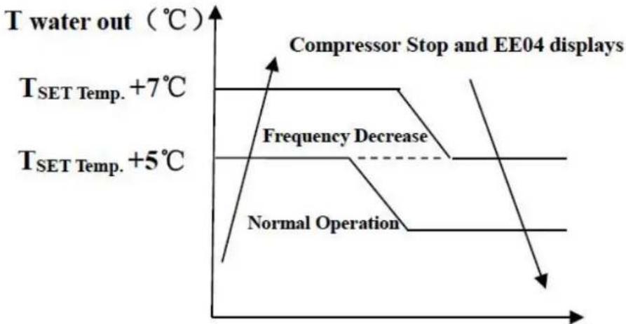
- In heating mode, if the water out temperature is higher than the set temperature over 7^ C, LED controller displays EE04 for water over-heating protection.
line
| Condition | Temperature (°C) | |---|---| | Compressor Stop and EE04 displays | - | | Frequency Decrease | - | | Normal Operation | - | | T_SET Temp. +5°C | - | | T_SET Temp. +7°C | - | | T water out (°C) | - |EE04 Water Overheating Protection
For example as below:
| Mode | Output water temperature | Set point temperature | Condition | Malfunction |
| Heating mode | 36°C | 29°C | Tout -Tset ≧7°C | EE04 Overheating protection for water temperature (d2- TH5) |
7.2 Other Malfunctions and Solutions (No display on LED wire controller)
| Malfunctions | Observing | Reasons | Solution |
| Heat pump is not running | LED wire controller no display. | No power supply | Check cable and circuit breaker if it is connected |
| LED wire controller. displays the actual time. | Heat pump under standby status | Startup heat pump to run. | |
| LED wire controller displays the actual water temperature. | 1. Water temperature is reaching to setting value, HF under constant temperature status.2. Heat pump just starts to run.3. Under defrosting. | 1. Verify water temperature setting.2. Startup heat pump after a few minutes.3. LED wire controller should display "Defrosting". | |
| Short running | LED displays actual water temperature, no error code displays. | 1. Fan NO running.2. Air ventilation is not enough.3. Refrigerant is not enough | 1. Check the cable connection between the motor and fan, necessary, it should be replaced.2. Check the location of heat pump unit, and eliminate all obstacles to make good air ventilation.3 Replace or repair the heat pump unit. |
| water stains | Water stains on heat pump unit. | 1. Concreting.2. Water leakage. | 1. No action.2. Check the titanium heat exchanger carefully if it is any defect. |
| Too much ice or evaporator | Too much ice on evaporator. | 1. Check the location of heat pump unit, and eliminate all obstacles to make good air ventilation.2. Replace or repair the heat pump unit. |
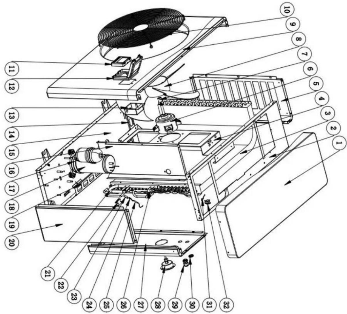
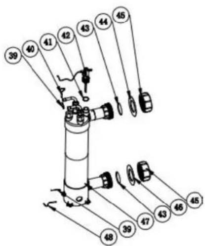
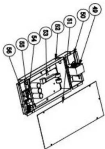
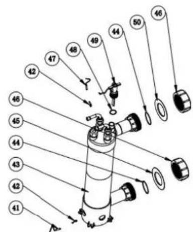
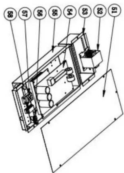
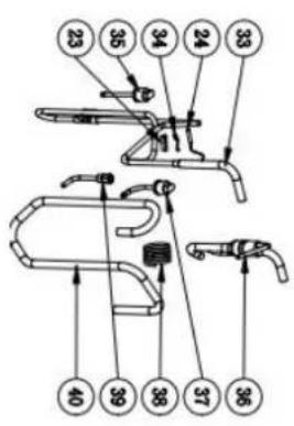
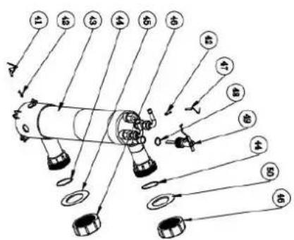
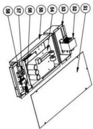
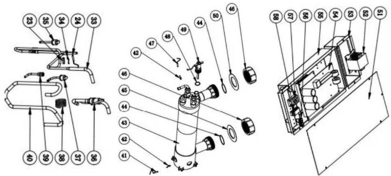
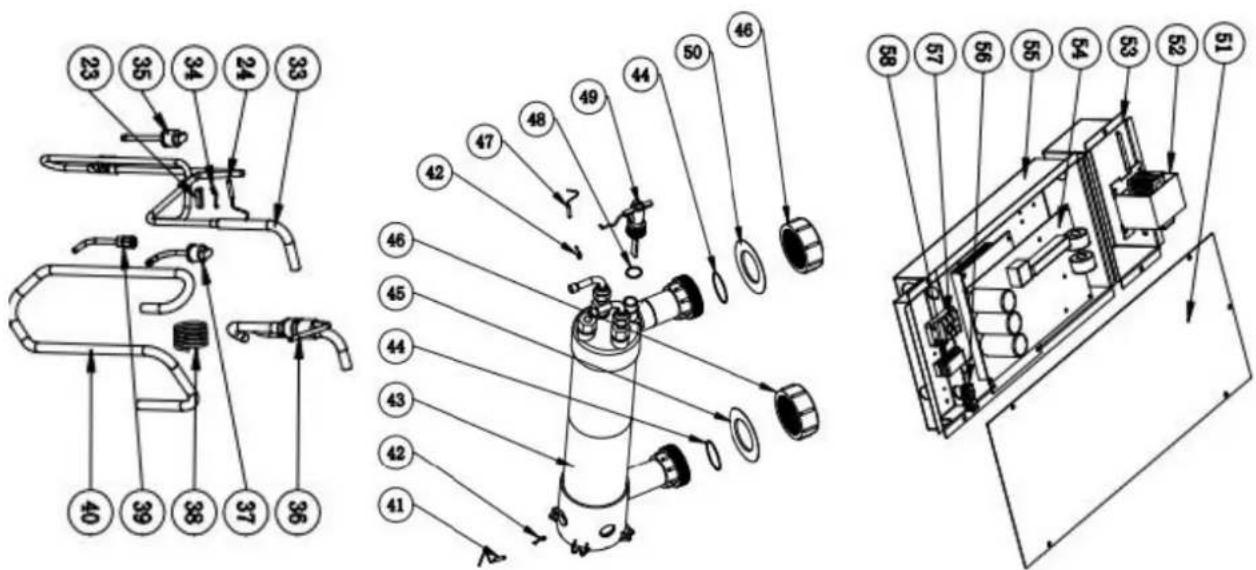
- Exploded Diagram
- 1 Exploded Diagram
Model: HPGI50
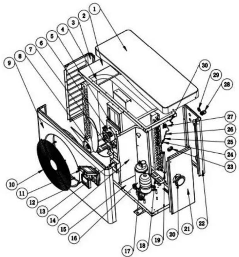
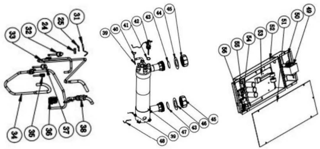
| No | Spare parts | No | Spare parts |
| 1 | Top cover | 32 | Cable connector |
| 2 | Top frame | 33 | Four-way valve coil |
| 3 | Left Panel | 34 | Four-way valve |
| 4 | Evaporator | 35 | Ambient temp. sensor |
| 5 | Fan motor bracket | 36 | Exhaust temp. sensor |
| 6 | Fan motor | 37 | High pressure switch |
| 7 | Evaporator pad | 38 | Exhaust pipe |
| 8 | Fan blade | 39 | Back gas piping |
| 9 | Front Panel | 40 | Needle Valve |
| 10 | Ventilation grid | 41 | Capillary |
| 11 | Waterproof box | 42 | Low pressure switch |
| 12 | Controller | 43 | Pipe (Titanium exchanger to Capillary |
| 13 | Controller box | 44 | Heat exchanger Sensor Clip |
| 14 | Isolation panel | 45 | Water outlet temp. sensor |
| 15 | Base tray | 46 | Rubber ring |
| 16 | Compressor | 47 | Water flow switch |
| 17 | Compressor heating belt | 48 | O' ring |
| 18 | Evaporator pad | 49 | Red rubber ring |
| 19 | Evaporator gas collecting pipe | 50 | Water connection |
| 20 | Pressure gauge | 51 | Blue rubber ring |
| 21 | Right Panel | 52 | Titanium heat exchanger |
| 22 | Back panel | 53 | Water inlet temp. sensor |
| 23 | B-shaped rubber fixing block | 54 | Reactor |
| 24 | Sensor casing pipe | 55 | Reactor box |
| 25 | Sensor casing pipe spring leaf | 56 | Electric box cover |
| 26 | Coil temp. sensor | 57 | Electric box |
| 27 | Ambient temp. sensor Clip | 58 | PCB |
| 28 | Cable connector | 59 | 3-position terminal |
| 29 | Wire loop with film | 60 | Clamp |
| 30 | Ambient temp. sensor | 61 | 2-position terminal |
| 31 | Pressure gauge |
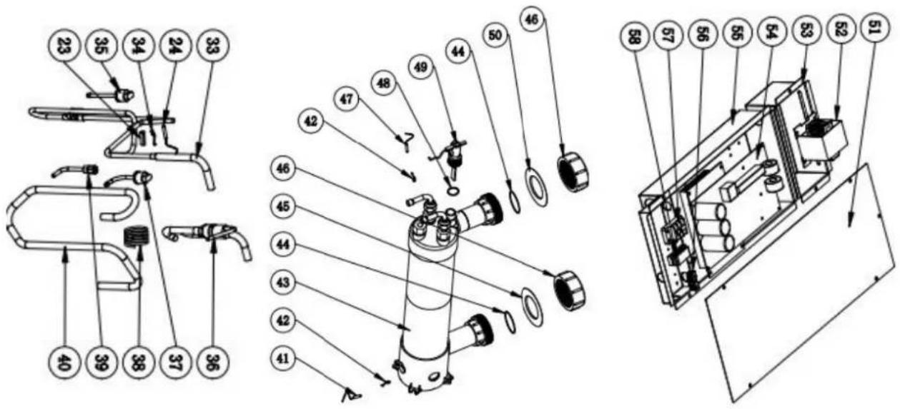
Model: HPGI60/70/85

| No | Spare parts | No | Spare parts |
| 1 | Top cover | 30 | Wire loop with film |
| 2 | Top frame | 31 | Ambient temp. sensor Clip |
| 3 | Evaporator | 32 | Ambient temp. sensor |
| 4 | Fan motor bracket | 33 | Exhaust pipe |
| 5 | Left Panel | 34 | Exhaust temp. sensor |
| 6 | Fan motor | 35 | High pressure switch |
| 7 | Casing pipe | 36 | Pipe (Titanium heat exchanger to Capillary |
| 8 | Fan blade | 37 | Low pressure switch |
| 9 | Front Panel | 38 | Capillary |
| 10 | Ventilation grid | 39 | Needle Valve |
| 11 | Controller | 40 | Back gas piping |
| 12 | Waterproof box | 41 | Water inlet temp. sensor |
| 13 | Controller box | 42 | Heat exchanger Sensor Clip |
| 14 | Evaporator pad | 43 | Titanium heat exchanger |
| 15 | Base tray | 44 | Joint seal ring |
| 16 | Isolation panel | 45 | Blue rubber ring |
| 17 | Compressor heating belt | 46 | Water connection |
| 18 | Compressor | 47 | Water inlet temp. sensor |
| 19 | Evaporator pad | 48 | Joint seal ring |
| 20 | Right Panel | 49 | Water flow switch |
| 21 | Evaporator gas collecting pipe | 50 | Red rubber ring |
| 22 | rubber fixing block | 51 | Electric box cover |
| 23 | Sensor casing pipe | 52 | Reactor |
| 24 | Sensor casing pipe spring leaf | 53 | Reactor box |
| 25 | Coil temp. sensor | 54 | PCB |
| 26 | Distribution pipe | 55 | Electric box |
| 27 | Back panel | 56 | 2-position terminal |
| 28 | Pressure gauge | 57 | 3-position terminal |
| 29 | Cable connector | 58 | Clamp |
9. Maintenance
Warning!
-Before any maintenance work on the appliance, you must cut the electricity supply as there is a risk of electric shock which may cause material damage, serious injury or even death.
- It is recommended that the appliance undergo general servicing at least on a yearly basis to ensure its proper operation, maintain performance levels and prevent any possible failures. These operations are carried out at the user's expense, by a qualified technician. for maintenance to be carried out by a qualified technician.
-For maintenance to be carried out by a qualified technician, please read the safety instructions in the previous pages provided in the chapter entitled "maintenance: warnings concerning appliances containing R32 refrigerant" before performing any of the maintenance operations described below.
(1) You should check the water supply system regularly to avoid the air entering the system and occurrence of low water flow, because it would reduce the performance and reliability of HP unit.
(2) Clean your pools and filtration system regularly to avoid the damage of the unit as a result of the dirty of clogged filter.
(3) In another way, you should check the unit is water fully before the unit start to run again.
(4) After the unit is conditioned for the winter season, it is recommended to cover the heat pump with special winter cover.
(5) When the unit is running, there is all the time a little water discharge under the unit.
(6) Please always empty the water in heat pump during winter time or when the ambient temperature drops below 0^ C, or else the Titanium exchanger will be damaged because of being frozen, in such case, your warranty will be lost.
* Above data is subject to update without prior notice.
**Check our packaging or website for more details.
2. Dimensión (mm)
Model: HPGI50

Model: HPGI60/70/85


natural_image
Technical line drawing of a rectangular industrial or laboratory equipment unit with control panel and side gauges (no text or symbols)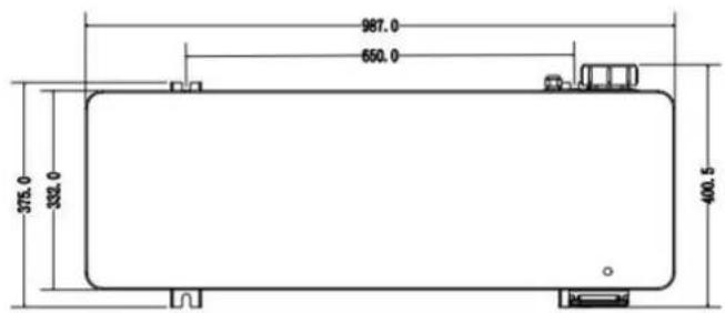
natural_image
Three-panel photo showing a connector with colored wires and connectors, no visible text or symbolsFoto 1 Foto 2 Foto 3
Foto 4
NOTA:
natural_image
Close-up of a white plastic pipe fitting with a small connector, mounted on a plain surface (no text or symbols visible)Photo(2)
Photo(3)
natural_image
Close-up of a white electronic device front panel with multiple colored wires and a black indicator button (no visible text or symbols)Photo(4)
natural_image
Close-up of a green printed circuit board with various electronic components and connectors (no visible text or symbols)line
| Temperature (°C) | Condition | |---|---| | 7 | Compressor Stop and EE04 displays | | 5 | Normal Operation | | - | Frequency Decrease |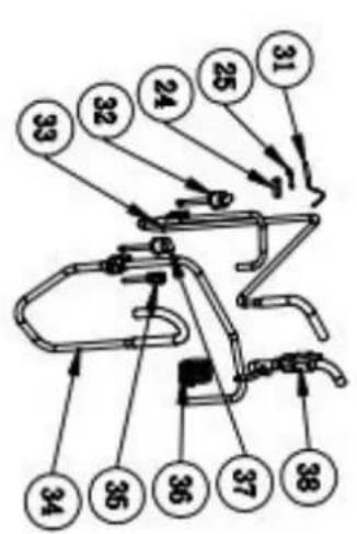

natural_image
Technical line drawing of a large air conditioning fan with labeled dimensions (987.0 and 668.0), no text or symbols on the fan itself.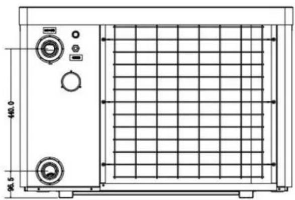
natural_image
Technical line drawing of a rectangular industrial machine with control panel and side gauges (no text or symbols)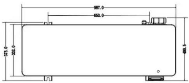
3. Installation et raccordement
3.1 Installation
natural_image
Close-up of a small transparent container with a circular hole on a dark textured base, placed on a wooden floor (no text or symbols visible)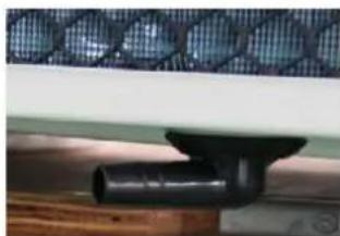
natural_image
Close-up of a black pipe fitting attached to a wooden surface, with a mesh-patterned panel on the wall (no text or symbols visible)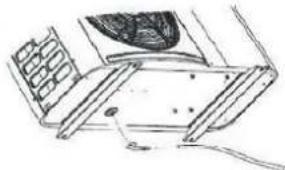
natural_image
Technical line drawing of a mechanical assembly with no visible text or symbols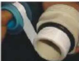
natural_image
Close-up of a hand holding a white cylindrical object with a blue ring, possibly a mechanical component or tool (no visible text or symbols)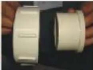
natural_image
Two white plastic cylindrical objects with side grooves, held by hands (no text or symbols visible)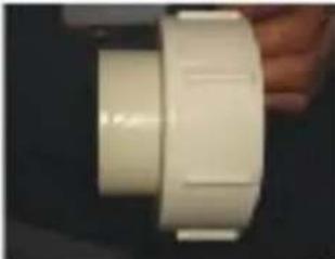
natural_image
Close-up of a white plastic cylindrical component with a flat top, held by a hand (no visible text or symbols)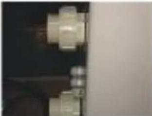
natural_image
Close-up of two metallic mechanical components against a dark background (no visible text or symbols)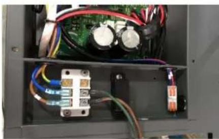
natural_image
Interior view of an electronic control panel with visible wiring, capacitors, and a circuit board (no text or symbols)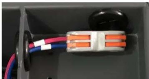
natural_image
Close-up of a small electronic component with colored wires and connectors (no visible text or symbols)Patin caoutchouc anti-vibration
natural_image
Three-panel photo showing electrical connectors with wires and colored wires, no visible text or symbolsPhoto 1 Photo 2 Photo 3
NOTE:
natural_image
Close-up of a white plastic pipe fitting with a small protrusion (no text or symbols visible)
natural_image
Close-up of a white electronic device front panel with multiple colored wires and connectors (no visible text or symbols)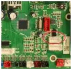
natural_image
Close-up of a green printed circuit board with various electronic components (no visible text or symbols)line
| Condition | Temperature (°C) | |---|---| | Compressor Stop and EE04 displays | T_SET Temp. +7°C | | Compressor Stop and EE04 displays | T_SET Temp. +5°C | | Frequency Decrease | T_SET Temp. +5°C | | Normal Operation | T_SET Temp. +5°C |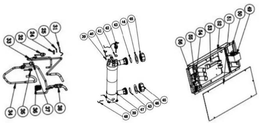

Model:HPGI60/70/85

natural_image
Technical line drawing of a rectangular industrial machine with control panel and side-mounted buttons (no text or symbols)
natural_image
White electronic device with coiled cable and indicator lights (no visible text or symbols)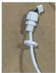
natural_image
Close-up of a white plastic electrical plug with a terminal connector (no visible text or symbols)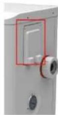

natural_image
Close-up of a white electrical outlet with multiple blue and red cables connected to terminals (no visible text or symbols)
natural_image
Close-up of a green printed circuit board with various electronic components and traces (no visible text or symbols)Tset = Tsetting Wassertemperatur
Tset-0.5 = less 0.5^ C than Tsetting temperatur; Tset-0.5 = 28-0.5=27.5°C
Tset+0.5= more 0.5°C than Tsetting temperatur; Tset+ 0.5 = 28+0.5=28.
line
| Condition | Temperature Change | | --------------------- | ------------------- | | Compressor Stop and EE04 | +7°C | | Frequency Decrease | - | | Normal Operation | +5°C |EE04 Water Overheating Protection
Zum Beispiel unten:


Modello: HPGI60/70/85


natural_image
Technical line drawing of a rectangular industrial or laboratory equipment unit with control panel and side gauges (no text or symbols)
NOTA:
natural_image
Close-up of a white plastic electrical plug with a coiled cable (no visible text or symbols)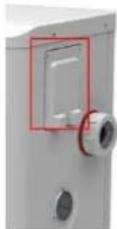

natural_image
White electrical circuit box with multiple blue and red connectors, no visible text or symbols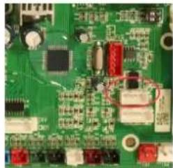
natural_image
Close-up of a green printed circuit board with various electronic components (no visible text or symbols)line
| Condition | Temperature (°C) | |---|---| | Compressor Stop and EE04 displays | 7 | | Frequency Decrease | 5 | | Normal Operation | 5 |

natural_image
Technical line drawing of a rectangular industrial or electrical enclosure with internal grid structure and two circular components (no text or symbols)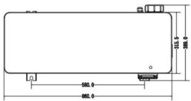
Model: HPGI60/70/85
natural_image
Technical line drawing of a rectangular industrial machine with control panel and side-mounted gauges (no text or symbols)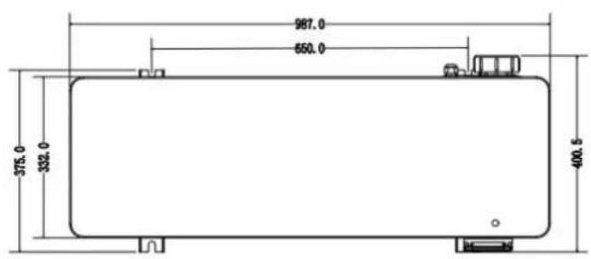
4.3 Connection to the filtration pump
natural_image
Three-panel photo showing electrical plug connections with wires and connectors (no visible text or symbols)Foto 1 Foto 2 Foto 3
OPMERKING:
natural_image
White electronic device with coiled cable and indicator lights (no visible text or symbols)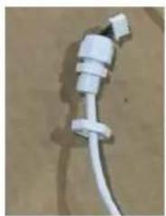
natural_image
Close-up of a white plastic electrical plug with a coiled cable (no visible text or symbols)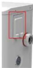
natural_image
Close-up of a white electrical outlet with multiple blue and red cables, no visible text or symbols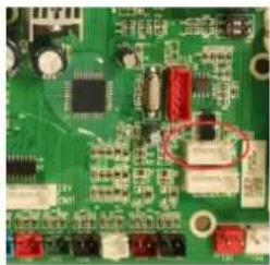
natural_image
Close-up of a green printed circuit board with various electronic components and traces (no visible text or symbols)Tset- 0.5 = 28-0.5=27.5°C
Tset+ 0.5 = 28+0.5=28.5°C
line
| Condition | Temperature (°C) | |---|---| | Compressor Stop and EE04 displays | 7 | | Frequency Decrease | 5 | | Normal Operation | 5 |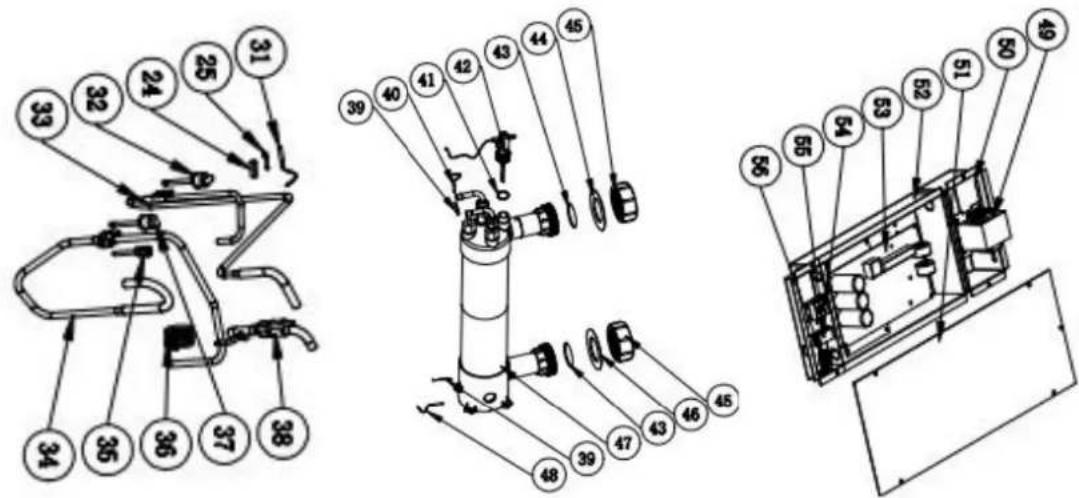
natural_image
Technical line drawing of a rectangular industrial or laboratory equipment unit with control panel and side gauges (no text or symbols)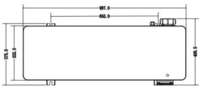
3.3 Arranjo típico
3.4 Ajustar o bypass
4.2 Accessories Installation
natural_image
Close-up of a small white object placed on a black textured base, placed on a wooden floor (no text or symbols visible)Bases antivibração
NOTA:
Tset-0.5 = less 0.5°C than Tsetting temperatura, Tset-0.5 = 28-0.5=27.5°C
Tset+0.5= more 0.5°C than Tsetting temperatura, Tset+ 0.5 = 28+0.5=28.5°C
line
| Condition | Temperature (°C) | |---|---| | Compressor Stop and EE04 displays | - | | Frequency Decrease | - | | Normal Operation | - | | T_SET Temp. +5°C | - | | T_SET Temp. +7°C | - | T water out (°C) | - |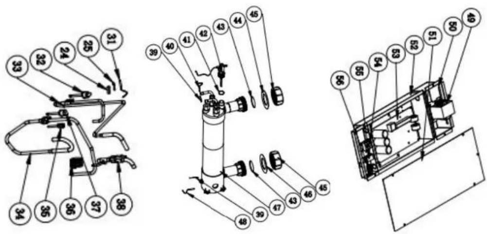
natural_image
Technical line drawing of a rectangular industrial or electrical enclosure with grid pattern and two circular components (no text or symbols)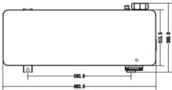
Model: HPGI60/70/85
natural_image
Technical line drawing of a rectangular industrial or laboratory equipment unit with control knobs and a grid-patterned panel (no text or symbols)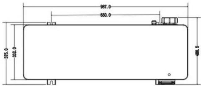
UWAGA:
natural_image
White electronic device with coiled white cables, no visible text or symbols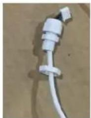
natural_image
Close-up of a white plastic electrical plug with a coiled cable (no text or symbols visible)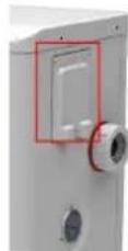

natural_image
Close-up of a white electrical outlet with multiple blue and red cables connected to a grid of connectors (no visible text or symbols)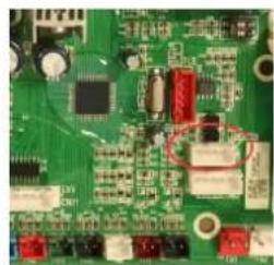
natural_image
Close-up of a green printed circuit board with various electronic components (no visible text or symbols)
1.1 In accordance with these provisions, the seller guarantees that the product corresponding to this guarantee ("the Product") is in perfect condition at the time of delivery.
1.2 The Guarantee Term for the Product is two (2) years from the time it is delivered to the purchaser.
1.3 In the event of any defect in the Product that is notified by the purchaser to the seller during the Guara Term, the seller will be obliged to repair or replace the Product, at his own cost and wherever he deems suitable unless this is impossible or unreasonable.
1.4 If it is not possible to repair or replace the Product, the purchaser may ask for a proportional reduction in the price or, if the defect is sufficiently significant, the termination of the salescontract.
1.5 The replaced or repaired parts under this guarantee, will not extend the guarantee period of the original Product, but will have a separate guarantee.
1.6 In order for this guarantee to come into effect, the purchaser must provide proof of the date of purchase delivery of the Product.
1.7 If, after six months from the delivery of the Product to the purchaser, he notifies a defect in the Product purchaser must provide proof of the origin and existence of the alleged defect.
1.8 This Guarantee Certificate is issued without prejudice to the rights corresponding to consumers under national regulations.
2 INDIVIDUAL TERMS
2.1 This guarantee covers the products referred to in this manual.
2.2 This Guarantee Certificate will only be applicable in European Union countries.
2.3 For this guarantee to be effective, the purchaser must strictly follow the Manufacturer's instructions included in the documentation provided with the Product, in cases where it is applicable according to the range of a model of the Product.
2.4 When a time schedule is specified for the replacement, maintenance or cleaning of certain parts or components of the Product, the guarantee will only be valid if this time schedule has been followed.
3 LIMITATIONS
3.1 This guarantee will only be applicable to sales made to consumers, understanding by “consumer”, a person who purchases the Product for purposes not related to his professional activities.
3.2 The normal wear resulting from using the product is not guaranteed. With respect to expendable or consumable parts, components and/or materials, such as batteries, light bulbs, etc. the stipulations in the documentation provided with the Product, will apply.
3.3 The guarantee does not cover those cases when the Product; (I) has been handled incorrectly; (II) has been repaired, serviced or handled by non- authorised people or (III) has been repaired or serviced not using original p In cases where the defect of the Product is a result of incorrect installation or start-up, this guarantee will only apply when said installation or start-up is included in the sales contract of the Product and has been conducted by the seller or under his responsibility.
ES - CERTIFICADO DE GARANTÍA 1
ASPECTOS GENERALES
MANUFACTURAS GRE, S.A.
ARITZ BIDEA Nº 57 BELAKO INDUSTRIALDEA, APARTADO
48100 MUNGUIA (VIZCAYA) ESPAÑA
Nº Reg. Ind. 48-06762
- Wereserve the right to change all or part of the articles or content of this document, without prior notice
- Nos reservamos el derecho de cambiar total o parcialmente las características de nuestros artículos o el contenido de este documento sin previoaviso
- Nous nous réservons le droit de modier totalement ou en partie les caractéristiques de nos articles ou le contenu ce document sans préavis
- Wir behalten uns das Recht vor, die technischen Daten unserer Artikel oder den Inhalt dieses Dokumentes ohne vorherigen Hinweis ganz oder teilweise zu ändern
- Ci riserviamo il diritto di cambiare totalmente o parzialmente le caratteristiche tecniche dei nostri prodotti ed il contenuto di questo documento senza nessun preavviso
- Wij behouden ons het recht voor geheel of gedeeltelijk de kenmerken van onze artikelen of de inhoud van deze handleiding zonder voorafgaand bericht te wijzigen
- Reservamo-nos o direito de alterar, total ou parcialmente, as características dos nossos artigos ou o conteúdo deste documento sem avisoprévio.
- Zastrzegamy sobie prawo do zmiany w całości lub części niniejszej instrukcji bez uprzedniejinformacji
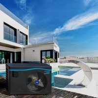
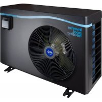

- inverter pool heating
- INDEX FOR DIFFERENT LANGUAGES
- GENERAL WARNINGS
- WARNINGS CONCERNING APPLIANCES CONTAINING REFRIGERANT R32
- MAINTENANCE: WARNINGS CONCERNING APPLIANCES CONTAINING R32 REFRIGERANT
- Work procedure
- General work area
- Check for the presence of refrigerant
- Check for the presence of a fire extinguisher
- No source of ignition
- Area ventilation
- Refrigeration equipment check
- Electric component check
- Repair of insulated components
- Repair of intrinsically safe components
- Wiring
- Detection of flammable refrigerant
- Removal and discharge
- Loading procedures
- Dismantling
- TROUBLESHOOTING
- LABELLING
- RECOVERY
- RECYCLING
- ADVERTENCIAS
- ALGEMENE WAARSCHUWINGEN
- WAARSCHUWINGEN MET BETREKKING TOT ELEKTRISCHE APPARATEN
- Swimming Pool Heat Pump User and Service manual
- INDEX
- heat pump.
- Specifications
- Dimension (mm)
- Installation and connection
- Notes
- Attention:
- Heat pump placement
- Fresh air - 2. Electricity - 3. Swimming pool filters
- Distance from your swimming pool
- Check-valve installation
- Typical arrangement
- Adjusting the bypass
- Electrical connection
- Initial operation
- Water Flow Switch:
- Condensation
- Operating modes for optimal use
- Accessories
- Accessories list
- Accessories Installation
- Anti-vibration bases
- Draining jet
- Water Inlet & outlet junction
- Cable wiring
- Water pump wiring (Dry contact)
- Connection to the filtration pump
- Electrical Wiring
- SWIMMING POOL HEAT PUMP WIRING DIADRAM
- NOTE:
- Installation of the remote control
- Display Controller Operation
- The buttons of LED wire controller
- The keys and their operations
- button
- and button
- button
- Heating priority (see the paragraph 6.9), option of connection
- System reset function
- Press
- 6.2.6
- 6.2.7
- 6.2.8
- 6.2.9
- 6.2.10
- 6.2.11
- Troubleshooting
- Remarks:
- Maintenance
- Warning!
- Dimensión (mm)
- NOTA:
- Installation et raccordement
- Installation
- Patin caoutchouc anti-vibration
- OPMERKING:
- Arranjo típico
- Ajustar o bypass
- Bases antivibração
- UWAGA:
- INDIVIDUAL TERMS
- LIMITATIONS
- ES - CERTIFICADO DE GARANTÍA 1
- ASPECTOS GENERALES
Brand : GRE
Model : HPGI50
Category : Heat pump