
VFTM320 IP66 - Frequency converter Soler & Palau - Free user manual and instructions
Find the device manual for free VFTM320 IP66 Soler & Palau in PDF.
| Brand | Soler & Palau |
| Model | VFTM320 IP66 |
| Product type | Variable frequency drive |
| Protection rating | IP66 |
| Power supply | Single-phase 230 V or three-phase 400 V, 50/60 Hz |
| Output frequency | 0 to 50/60 Hz |
| Control modes | Manual proportional (built-in or remote potentiometer), PI control (constant pressure/flow) |
| Analog inputs | 0-10 V and 4-20 mA |
| Relay outputs | R1, R2 (programmable) |
| Motor connection cable | Shielded, maximum recommended length 50 m |
| Reconfiguration | Via menu, factory password: 1951 |
| Motor thermal protection | Can be activated, with manual or automatic restart |
| Default minimum speed | 20 Hz (adjustable) |
| Standard applications | Manual proportional control, staircase pressurization (50 Pa) |
| Advanced applications | Control with external sensor (CO2, temperature, humidity), PI constant flow/pressure control |
| Compatible remote potentiometer | REB-ECOWATT (max. cable length 25 m) |
| Safety | Installation by qualified professional; compliance with LV, machinery, EMC directives |
| Maintenance | Disconnect the device before any intervention |
| Recycling | Packaging and used device to be disposed of at appropriate recycling points |
| Warranty | Manufacturing defects covered by S&P warranty |
Frequently Asked Questions - VFTM320 IP66 Soler & Palau
User questions about VFTM320 IP66 Soler & Palau
0 question about this device. Answer the ones you know or ask your own.
Ask a new question about this device
Download the instructions for your Frequency converter in PDF format for free! Find your manual VFTM320 IP66 - Soler & Palau and take your electronic device back in hand. On this page are published all the documents necessary for the use of your device. VFTM320 IP66 by Soler & Palau.
USER MANUAL VFTM320 IP66 Soler & Palau
ESPAÑOL
INDICE
- RECOMENDACIONES......4
- INFORMACION GENERAL .... 5
natural_image
Industrial control unit with digital display and control panel (no visible text or symbols)line
| Al3 (mA) | Frequency (Hz) | |---|---| | CrL3 | 7.2* | | CrH3 | 14.4* | | HSP | - | | LSP | - |2.1 Cable for connection to the electrical supply....19
2.2 Inverter reconfiguration....19
2.3 Manual reset/Automatic reset....20
2.4 Changing the minimum/ maximum speed 20
2.5 Preparing the motor thermal protection 21
2.6 To achieve theStart/stop function with an external switch 21
- STANDARD APPLICATIONS OF THE INVERTER (without reconfiguring the inverter) 22
3.1. Manual proportional control with built in potentiometer .....22
3.2. Use the inverter in pressurised stairwell systems....23
- APPLICATIONS THAT REQUIRE RECONFIGURATION OF THE INVERTER ....24
4.1. Manual proportional control with Reb-Ecowatt remote potentiometer....24
4.2. Automatic proportional control with a 4-20 mA signal from an external analogue sensor (CO2, Temperature or relative humidity) .....25
4.3. PI control in constant pressure/ Air volume systems with an external analogue sensor and 0-10V sensor ....27
4.4 PI control in constant pressure / Air volume systems with an external analogue sensor and 4-20 mA Sensor ....30
1. RECOMMENDATIONS
You have purchased a frequency inverter designed specifically by Soler & Palau to perform the functions described in the table of contents.
Before you install and start up this product, please read this instruction book carefully because it contains important information for your safety and the safety of users during installation, use and maintenance. Once installation is complete, please pass the instruction book on to the end user.
Please check that the equipment is in perfect condition when you unpack it since any factory defect is covered under the S&P guarantee. Please also check that the equipment is the one that you have ordered and that the information on the instruction plate meets your requirements.
Not every fan can be adjusted using frequency inverters.
Make sure that the fan you want to regulate is compatible with the frequency inverter you have purchased.
Transport and handling
- The equipment packaging has been designed to withstand normal transport conditions. The equipment must not be transported without its original packaging as it could become damaged.
- The product must be stored in its original packaging and in a dry and clean place until it is installed. Do not accept any equipment that is not supplied in its original packaging or that shows signs of having been tampered with.
- Prevent the packaging from falling and being knocked and do not place heavy loads on it.
Important for your safety and the safety of users
- The product must be installed by a qualified specialist.
- Ensure that installation complies with mechanical and electrical regulations in each country.
- Once commissioned, the equipment must comply with the following Directives:
• Low Voltage Directive 2006/95/CE
• European Machinery Directive 2006/42/CE
• Electromagnetic Compatibility Directive 2004/108/CE
- Do not use this equipment in explosive or corrosive atmospheres.
Safety during Installation
- Before you handle this equipment, ensure it is disconnected from the mains power supply.
- Check that the mains voltage and frequency are the same as specified on the name plate.
- Follow the wiring diagram to make the electrical connections.
- Check that the earthing, if any, is correct and that the thermal and surge protection has been connected and are within the relevant limits.
Maintenance
- Before you handle the equipment, ensure it is disconnected from the mains and that no one can switch it on during the maintenance procedure.
- During any maintenance and repair work, safety regulations in force in each country must be observed.
Recycling
- EU regulations and our commitment to future generations oblige us to recycle used materials. Please remember to dispose of all unwanted packaging materials at the appropriate recycling points, and to drop obsolete equipment at the nearest waste management point.
2. GENERAL INFORMATION
2.1 Cable for connection to the electrical supply
The cable for connection between the frequency inverter and the fan terminal box must be shielded, with a recommended maximum length of 50m.
IMPORTANT: The metal mesh of the shielded cable must be earthed in the fan terminal box.
If the fan is installed with a cable and an external terminal box, and the motor has its own terminal box connect the inverter shielded cable directly to the motor terminal box, removing the cable and the remote terminal box.
2.2 Inverter reconfiguration
Frequency inverters are pre-programmed to be used via proportional control with a built-in potentiometer (FR2 with jumper between 24V and LI3) or via PI control with a 0-10V voltage input (FR1 with jumper between 24V and LI1).
For other uses, some of the parameters configured in the frequency inverter must be re-programmed. To do so, use the following inverter commands:

Step 1. Unlock the inverter
To unlock the inverter, enter the password. The sequence is as follows:
- Press ESC until "rdy" appears on the screen.
- Press ENTER and rotate the wheel anti-clockwise until "SUP-" appears on the screen.
- Press ENTER and rotate the wheel clockwise until "COd-" appears on the screen.
- Press ENTER and rotate the wheel clockwise until "1951-" appears on the screen.
- The entered code flashes. At this time the inverter is unprotected.
Step 2. Enter programming mode
The inverter has 2 operating MODES, RUN and PROGRAMMING. To switch from one to the other keep ESC pressed for two seconds.
Location of the 3 Mode Leds.
Depending on how they are lit up, they indicate the selected mode:
- IN SEQUENCE→ RUN MODE
- SIMULTANEOUSLY→ PROGRAMMING MODE

- Keep ESC pressed down for 2 seconds until the 3 mode leds light up simultaneously. At that moment they are in Programming Mode.
Enter the parameters depending on the required use.
2.3 Manual reset – Automatic reset
The frequency inverters are delivered pre-programmed for automatic reset.
This means that in the event of a power cut, the fan will automatically switch on when the power returns.

IMPORTANT RISK OF ELECTROCUTION RISK OF SERIOUS INJURY
When is enable the thermal protection motor should review the need to use the manual restart function.
With the factory settings (automatic restart), once skipped the motor thermal protection, when is produced the motor cooling, it re-start automatically.
See section 2.3. to modify the automatic restart to manual restart.
If the motor connected to the inverter has thermal protection, the inverter must be re-programmed for manual reset.
IMPORTANT: If the thermal protection is activated it is necessary to wire the motor TP connections to the corresponding terminals of the inverter in order to achieve electrical protection.
- Keep ESC pressed down for 2 seconds until the 3 mode leds light up simultaneously. At the moment the inverter is in Programming Mode.
- Press ENTER and rotate the wheel until "FLt-" appears on the screen.
- Press ENTER and rotate the wheel until "Atr" appears on the screen.
- Press ENTER and rotate the wheel until "NO" appears.
- Press ENTER to confirm the value entered. If this value is different to the previous one, the display should flash.
- Press ESC to exit the "Atr" parameter.
- Press ESC to exit the "FLt-" menu.
- Keep ESC pressed down for 2 seconds until the 3 mode leds light up in sequence. It is now in RUN mode, available for automatic inverter operation.
Check that the "SW1" switch is in the "SOURCE" position
Install the indicated jumpers in the inverter terminal box.
Power the frequency inverter with suitable voltage for the inverter model in question.
2.4 Changing the minimum/ maximum speed
Frequency inverters are delivered pre-programmed with a minimum speed setting at 20 Hz.
Warning! The continued power supply of a motor at frequencies below 20 Hz can cause motor overheating and premature failure. Motors that have been working below 20 Hz will not be covered by warranty.

However, in overpressure applications stairs or escape routes, it is possible that in the situation of closed doors reduce the minimum speed of inverter to avoid exceeding the overpressure value established by the relevant regulations. This requires checking out the inverter and access to the programmation mode (steps 1 and 2 in section 2.2) and then perform the following configuration changes:
- Press ENTER and rotate the wheel anti-clockwise until "SEt-" appears on the screen.
- Press ENTER and rotate the wheel anti-clockwise until "LSP" appears on the screen.
- Press ENTER and rotate the wheel until the necessary value appears for the "Minimum frequency in Hz" parameter. Press ENTER to confirm the value entered. If this value is different to the previous one, the display should flash.
- Press ESC to exit the "LSP" parameter.
- Press ESC to exit the "Set-" menu.
In the same way, the "HSP" maximum frequency value must never be set above the frequency value for the mains power supply in the country where it is used.
2.5 Preparing the motor thermal protection
To enable the motor thermal protection, so that a motor overheating condition causes the inverter to stop, it is necessary to reprogram some of the parameters that are configured in the frequency inverter. This requires checking out the inverter to access to the program parameters (steps 1 and 2 in section 2.2) and perform the following configuration changes:
- Press ENTER and rotate the wheel until "FLt-" appears on the screen.
- Press ENTER and rotate the wheel until "Etf" appears on the screen.
- Press ENTER and rotate the Wheel until "L15" appears on the screen. Press ENTER to confirm the value entered. If this value is different to the previous one, the display should flash.
- Press ESC to exit the "Etf" parameter.
- Rotate the wheel until appears "LEt" on the screen.
- Press ENTER and rotate the wheel until appears "LO" on the screen. Press ENTER to confirm the value entered.
- Press ESC to exit the "LEt" parameter.
- Press ESC to "FLt" parameter.
- Keep ESC pressed down for 2 seconds until the 3 mode leds light up in sequence. It is now in RUN mode, available for automatic inverter operation.

IMPORTANT
RISK OF ELECTROCUTION
RISK OF SERIOUS INJURY
When is enable the thermal protection motor should review the need to use the manual restart function. With the factory settings (automatic restart), once skipped the motor thermal protection, when is produced the motor cooling, it re-start automatically.
See section 2.3. to modify the automatic restart to manual restart.
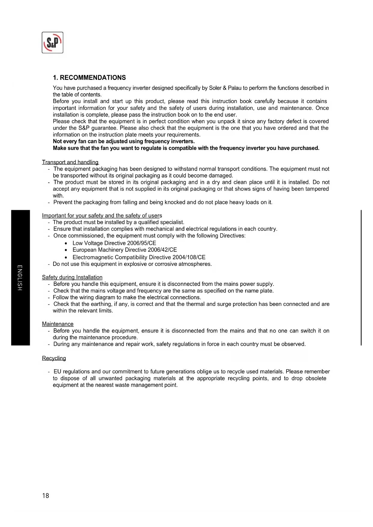
2.6 To achieve theStart/stop function with an external switch
This function is common to all systems where the inverter works with external sensors (pressure, airflow, CO2, temperature, humidity, etc.)
it is also possible to achieve the remote control function (start/stop) by means of an external switch with volt-free contacts.
For this it is necessary to use the corresponding switching diagram, replacing the existing a jumper between LI1 and 24 V for wiring to the external switch.
EXTERNAL SWITCH
3. STANDARD APPLICATIONS OF THE INVERTER (without reconfiguring the inverter)
3.1 MANUAL PROPORTIONAL CONTROL WITH BUILT IN POTENTIOMETER
3.1.1 Features
This configuration allows the user to vary the fan rotating speed using the inverter potentiometer.
The speed is adjusted using the potentiometer
RUN / STOP keys to start / stop motor rotation
Check that the converter power and current are higher than the connected motor power and current
natural_image
Industrial control unit with open door and control panel (no visible text or symbols)3.1.2. Wiring diagram
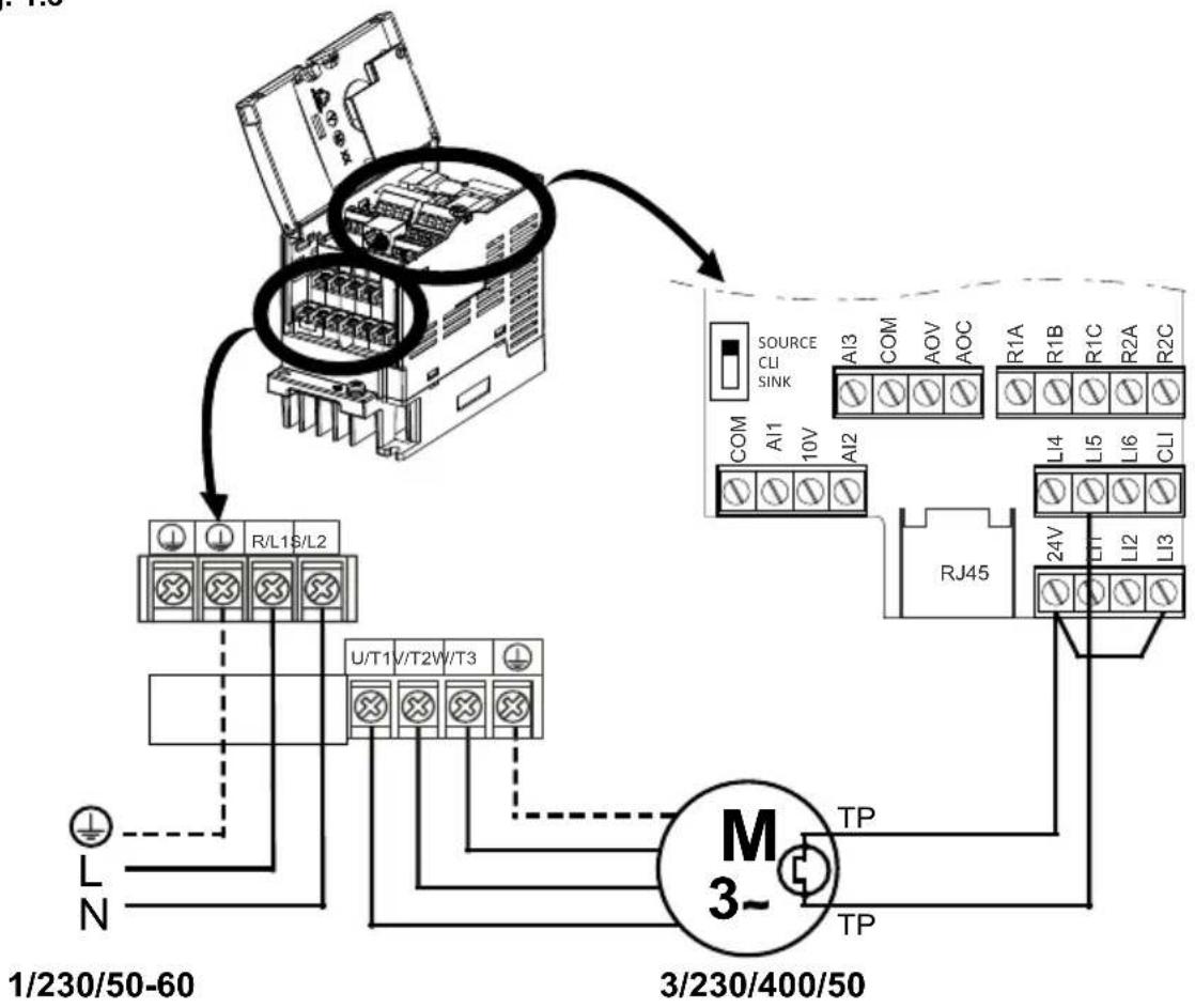
Follow the inverter-motor wiring diagram shown in the following illustrations depending on the type of motor used and whether this motor has thermal protection:
- Fig.1.1. Single phase power supply 1/230/50-60, three phase motor 230/400V without thermal protection (automatic reset)
- Fig.1.2 Three phase power supply 3/400/50-60, three phase motor 230/400 or 400V without thermal protection (automatic reset)
- Fig.1.3. Single phase power supply 1/230/50-60, three phase motor 230/400V with thermal protection (manual reset)
- Fig.1.4. Three phase power supply 3/400/50-60, three phase motor 230/400 or 400V with thermal protection (manual reset)
Check that the "SW1" switch is in the "SOURCE" position.
Install the indicated jumpers in the inverter terminal box.
Power the frequency inverter with suitable voltage for the inverter model in question.
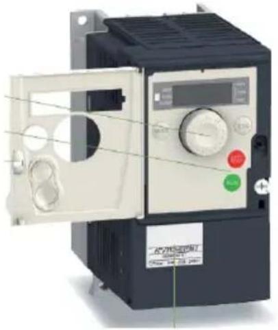
3.2. USE OF THE INVERTER IN PRESSURISED STAIRWELL SYSTEMS
3.2.1 Features
In this case, the equipment is used to guarantee a specific pressurised value in one room in relation to another.
A TDP-D differential pressure sensor with a display is necessary to start up this system.
The system will keep a value of 50 Pa in the pressurised building, as long as the TDP-D pressure sensor range is 0 to 100 Pa. Check this before you start up the system.
The frequency inverter will start automatically when it receives power and will perform PI controller functions
3.2.2 Installation diagram
flowchart
graph TD
    A["TDP PRESSURE SENSOR"] --> B["ROOM WITH ATMOSPHERIC PRESSURE"]
    A --> C["PRESSURISED ROOM"]
    A --> D["FAN"]
    D --> E["FREQUENCY INVERTER"]
    B --> F["Ground"]
    C --> G["Ground"]
    D --> H["Ground"]
3.2.3 Wiring diagram
Follow the inverter-motor wiring diagram shown in the following illustrations depending on the type of motor used and whether this motor has thermal protection:
- Fig.2.1. Single phase power supply 1/230/50-60, three phase motor 230/400V without thermal protection and 0-10V signal (automatic reset)
- Fig.2.2. Three phase power supply 3/400/50-60, three phase motor 230/400 or 400V without thermal protection and 0-10V signal (automatic reset)
- Fig.2.3. Single phase power supply 1/230/50-60, three phase motor 230/400V with thermal protection and 0-10V signal (manual reset)
IMPORTANT: Before carrying out the wiring read the point 2.3 and 2.5 to determine the type of restart to configure.
- Fig.2.4. Three phase power supply 3/400/50-60, three phase motor 230/400 or 400V with thermal protection and 0-10V signal (manual reset)
IMPORTANT: Before carrying out the wiring read the point 2.3 and 2.5 to determine the type of restart to configure:
Check that the "SW1" switch is in the "SOURCE" position
Install the indicated jumpers in the inverter terminal box.
Power the frequency inverter with suitable voltage for the inverter model in question.
The frequency inverter will start automatically when it receives power and will perform PI controller functions.
4. APPLICATIONS THAT REQUIRE RECONFIGURATION OF THE INVERTER
4.1 MANUAL PROPORTIONAL CONTROL WITH REB-ECOWATT REMOTE POTENTIOMETER
4.1.1 Features
This configuration allows the user to vary the fan rotating speed using the REB-ECOWATT remote potentiometer.
In this case the REB-ECOWATT start-stop function cannot be used.
The maximum cable length between the REB-ECOWATT and the frequency inverter is 25m
For this use, some of the parameters configured in the frequency inverter must be re-programmed.
Access the programming mode (steps 1 and 2 in section 2.2) and then perform the following configuration changes:
- Press ENTER and rotate the wheel until "FUN-" appears on the screen.
- Press ENTER and rotate the wheel until "PI" appears on the screen.
- Press ENTER and rotate the wheel until « PIF » appears on the screen.
- Press ENTER and rotate the wheel until appears "No"
- Press ENTER to confirm the value entered. If this value is different to the previous one, the display should flash.
- Press ESC to exit the "PIF" parameter.
- Press ESC to exit the "PIF-" menu.
- Press ESC to exit the "FUN" menu.
- Keep ESC pressed down for 2 seconds until the 3 mode leds light up in sequence. It is now in RUN mode, available for automatic inverter operation.
4.1.2 Wiring diagram
Follow the inverter-motor wiring diagram shown in the following illustrations depending on the type of motor used and whether this motor has thermal protection:
- Fig.3.1. Single phase power supply 1/230/50-60, three phase motor 230/400V without thermal protection, without using the REB-ECOWATT start-stop function (automatic reset)
- Fig.3.2. Three phase power supply 3/400/50-60, three phase motor 230/400 or 400V without thermal protection, without using the REB-ECOWATT start-stop function (automatic reset)
- Fig.3.3. Single phase power supply 1/230/50-60, three phase motor 230/400V with thermal protection, without using the REB-ECOWATT start-stop function (manual reset)
IMPORTANT: Before carrying out the wiring read the point 2.3 and 2.5 to determine the type of restart to configure. - Fig.3.4. Three phase power supply 3/400/50-60, three phase motor 230/400 or 400V with thermal protection, without using the REB-ECOWATT start-stop function (manual reset)
IMPORTANT: Before carrying out the wiring read the point 2.3 and 2.5 to determine the type of restart to configure.
Check that the "SW1" switch is in the "SOURCE" position
Install the indicated jumpers in the inverter terminal box.
Power the frequency inverter with suitable voltage for the inverter model in question.
4.2 AUTOMATIC PROPORTIONAL CONTROL WITH A 4-20 mA SIGNAL FROM AN EXTERNAL ANALOGUE SENSOR (CO2, TEMPERATURE OR RELATIVE HUMIDITY)
4.2.1 Features
In this case, the equipment is used to regulate the air volume in accordance with the value measured by an external sensor.
The external sensor must emit a 4-20 mA analogue sensor.
With 0-10V input the input voltage values cannot be adjusted.
It is possible to change the behaviour of the proportional output by modifying the value of the LSP, HSP, CrL3 and CRH3 paramaters.
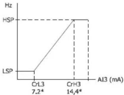
line
| Al3 (mA) | Frequency (Hz) | |---|---| | CrL3 | 7.2* | | CrH3 | 14,4* | | HSP | - | | LSP | - |In this case, some of the parameters configured in the frequency inverter must be re-programmed in the inverter to avoid exceeding the overpressure value established by the relevant regulations. Access the programming mode (steps 1 and 2 in section 2.2) and then perform the following configuration changes:
- Press ENTER and rotate the wheel anti-clockwise until "SEt-" appears on the screen.
- Press ENTER and rotate the wheel anti-clockwise until "LSP" appears on the screen.
- Press ENTER and rotate the wheel until the necessary value appears for the "Minimum frequency in Hz" parameter. Press ENTER to confirm the value entered. If this value is different to the previous one, the display should flash.
- Press ESC to exit the "LSP" parameter.
- Rotate the wheel until "HSP" appears on the screen
- Press ENTER and rotate the wheel until the necessary value appears for the "Maximum frequency in Hz" parameter. Press ENTER to confirm the value entered. If this value is different to the previous one, the display should flash.
- Press ESC to exit the "HSP" parameter.
- Press ESC to exit the "Set-" menu.
- Follow the method used to configure the two initial parameters until all of the parameters in the following table have been configured:
| MENU | Parameter | Value | Comment | |
| I_O- | CrL3 | 7.2 | Minimum reference value (mA) | |
| I_O- | CrH3 | 14.4 | Maximum reference value (mA) | |
| Ctl- | Fr2 | Al3 | Current type reference (mA) | |
| FUN- | PI- | PIF | No | Disable de PI function |
- Press ESC to exit the "CtL-" menu.
- Keep ESC pressed down for 2 seconds until the 3 mode leds light up in sequence. It is now in RUN mode, available for automatic inverter operation.
4.2.2 Wiring diagram
Follow the inverter-motor wiring diagram shown in the following illustrations depending on the type of motor used and whether this motor has thermal protection:
- Fig.4.1. Single phase power supply 1/230/50-60, three phase motor 230/400V without thermal protection and 4-20mA signal (automatic reset)
- Fig.4.2. Three phase power supply 3/400/50-60, three phase motor 230/400 or 400V without thermal protection and 4-20mA signal (automatic reset)
- Fig.4.3. Single phase power supply 1/230/50-60, three phase motor 230/400V with thermal protection and 4-20mA signal (manual reset)
IMPORTANT: Before carrying out the wiring read the point 2.3 and 2.5 to determine the type of restart to configure. - Fig.4.4. Three phase power supply 3/400/50-60, three phase motor 230/400 or 400V with thermal protection and 4-20mA signal (manual reset)
IMPORTANT: Before carrying out the wiring read the point 2.3 and 2.5 to determine the type of restart to configure.
Check that the "SW1" switch is in the "SOURCE" position.
Install the indicated jumpers in the inverter terminal box.
Power the frequency inverter with suitable voltage for the inverter model in question.
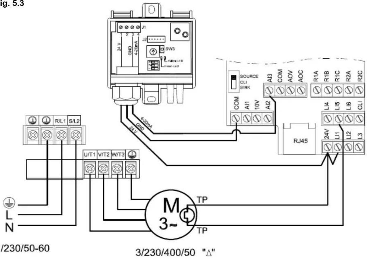
4.3 PI CONTROL IN CONSTANT PRESSURE / AIRVOLUME SYSTEMS WITH AN EXTERNAL ANALOGUE SENSOR AND 0-10V SENSOR
4.3.1 Features
Constant Air Volume (CAV)
The inverter is used to guarantee a specific air volume in a duct system, regardless of filters closing.
Constant Pressure (COP)
The inverter is used in variable airvolume systems to guarantee specific air pressure in the duct system, regardless of whether the dampers are open or closed. In both cases, the pressure must be constant in the duct system. The value of this pressure must be determined by experimenting during the system start-up process.
A TDP-D differential pressure sensor with display is necessary to start up this system.
The first attempt at making the adjustment will be by changing the sensor range. The established pressure values are:
| Value entered “rPI” | Pressure to be maintained in duct system (Pa) |
| 0-100 | 50 |
| 0-150 | 75 |
| 0-300 | 150 |
| 0-500 | 250 |
| 0-1000 | 500 |
If none of the values in the table above is suitable for the installation, you must establish the exact pressure setting by re-configuring the frequency inverter. (see point 7.3.)
4.3.2 Installation diagram
Constant Pressure Installation Diagram
flowchart
graph LR
    A["TDP PRESSURE SENSOR"] --> B["Filter"]
    B --> C["FAN"]
    C --> D["FREQUENCY INVERTER"]
    D --> E["Ground"]
Constant Flow Installation Diagram
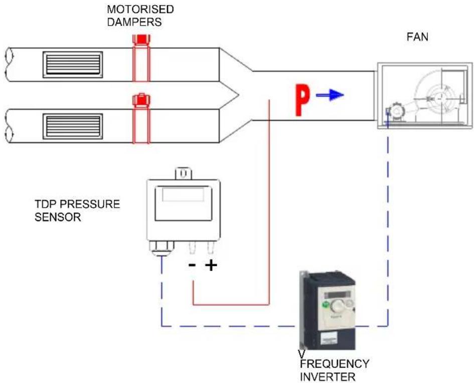
flowchart
graph TD
    A["MOTORISED DAMPERS"] --> B["FAN"]
    C["TDP PRESSURE SENSOR"] --> D["+"]
    D --> E["V FREQUENCY INVERTER"]
    B -->|P| E
    style A fill:#f9f,stroke:#333
    style C fill:#f9f,stroke:#333
    style B fill:#ccf,stroke:#333
    style E fill:#ccf,stroke:#333
4.3.3 Inverter reconfiguration
For this use, some of the parameters configured in the frequency inverter must be re-programmed. Access the programming mode (steps 1 and 2 in section 2.2) and then perform the following configuration changes:
- Press ENTER and rotate the wheel until "FUn-" appears on the screen.
- Press ENTER and rotate the wheel until "PI-" appears on the screen.
- Press ENTER and rotate the wheel until "rPI" appears on the screen.
- Press ENTER and rotate the wheel until the necessary value appears for the "Pressure to be maintained" parameter. Percentage out of selected range in pressure sensor".
| Required pressure at measurement point “P” (Pa) | Value entered “rPI” | Pressure sensor pressure range (Pa) |
| 10 | 10 | 0 – 100 |
| 20 | 20 | 0 – 100 |
| 30 | 30 | 0 – 100 |
| 40 | 40 | 0 – 100 |
| 60 | 60 | 0 – 100 |
| 80 | 80 | 0 – 100 |
| 100 | 33 | 0 – 300 |
| 120 | 40 | 0 – 300 |
| 180 | 60 | 0 – 300 |
| 200 | 66 | 0 – 300 |
| 300 | 60 | 0 – 500 |
| 350 | 70 | 0 – 500 |
| 400 | 80 | 0 – 500 |
- Press ENTER to confirm the value entered.
- Press ESC repeatedly until you reach the main menu.
- Keep ESC pressed down for 2 seconds until the 3 mode leds light up in sequence. It is now in RUN mode, available for automatic inverter operation.
Step 3. Reconfigure range in sensor
Select the TPD sensor pressure range in accordance with the values in the third column in the table above.
4.3.4 Wiring diagram
Follow the inverter-motor wiring diagram shown in the following illustrations depending on the type of motor used and whether this motor has thermal protection:
- Fig.5.1. Single phase power supply 1/230/50-60, three phase motor 230/400V without thermal protection and 0-10V signal (automatic reset).
- Fig.5.2. Three phase power supply 3/400/50-60, three phase motor 230/400 or 400V without thermal protection and 0-10V signal (automatic reset).
- Fig.5.3. Single phase power supply 1/230/50-60, three phase motor 230/400V with thermal protection and 0-10V signal.
IMPORTANT: Before carrying out the wiring read the point 2.3 and 2.5 to determine the type of restart to configure.
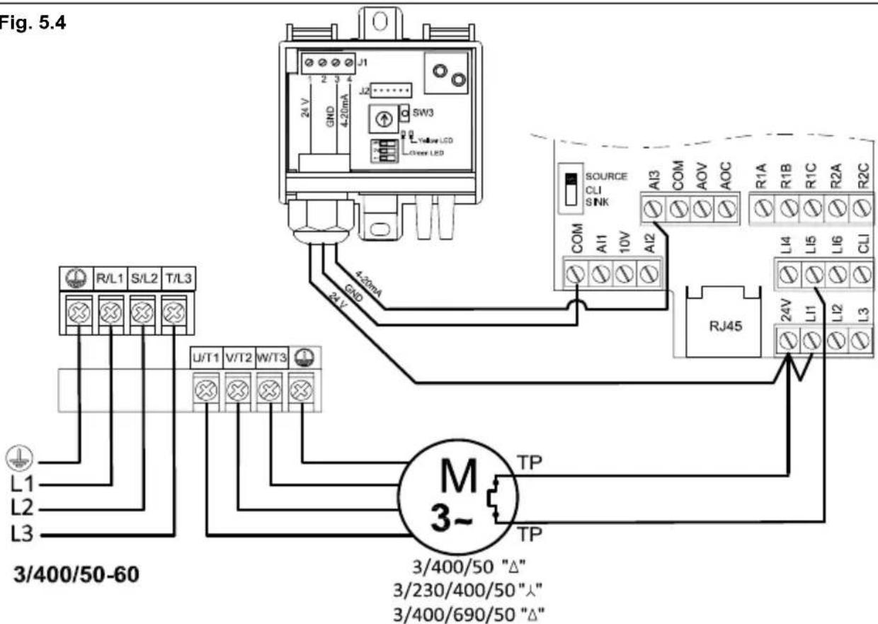
- Fig.5.4. Three phase power supply 3/400/50-60, three phase motor 230/400 or 400V with thermal protection and 0-10V signal.
IMPORTANT: Before carrying out the wiring read the point 2.3 and 2.5 to determine the type of restart to configure.
Check that the "SW1" switch is in the "SOURCE" position.
Install the indicated jumpers in the inverter terminal box.
Power the frequency inverter with suitable voltage for the inverter model in question.
The frequency inverter will start automatically when it receives power and will perform PI controller functions.
4.4. PI CONTROL IN CONSTANT PRESSURE / AIRVOLUME SYSTEMS WITH AN EXTERNAL ANALOG SENSOR AND 4-20Ma SENSOR
4.4.1 Features
The inverter is used to guarantee a specific setpoint value established by an analog sensor emitting a 4-20mA signal.
For this use, some of the parameters configured in the frequency inverter must be re-programmed. To do so, please see page XX.
- Keep ESC pressed down for 2 seconds until the 3 mode leds light up simultaneously. At the moment they are in Programming Mode.
- Press ENTER and rotate the wheel anti-clockwise until "SEt-" appears on the screen.
- Press ENTER and rotate the wheel anti-clockwise until "LSP" appears on the screen.
- Press ENTER and rotate the wheel until the necessary value appears for the "Minimum frequency in Hz" parameter. Press ENTER to confirm the value entered. If this value is different to the previous one, the display should flash.
- Press ESC to exit the "LSP" parameter.
- Rotate the wheel until "HSP" appears on the screen.
- Press ENTER and rotate the wheel until the necessary value appears for the "Maximum frequency in Hz" parameter. Press ENTER to confirm the value entered. If this value is different to the previous one, the display should flash.
- Press ESC to exit the "HSP" parameter.
- Press ESC to exit the "Set-" menu.
- Follow the method used to configure the two initial parameters until all of the parameters in the following table have been configured:
| MENU | Parameter | Value | Comment |
| Ctl- | Fr1 | Al3 | Current type reference (mA) |
- Press ESC to exit the "CtL-" menu.
- Keep ESC pressed down for 2 seconds until the 3 mode leds light up in sequence. It is now in RUN mode, available for automatic inverter operation.
4.4.2 Wiring diagram
Follow the inverter-motor wiring diagram shown in the following illustrations depending on the type of motor used and whether this motor has thermal protection:
- Fig.6.1. Single phase power supply 1/230/50-60, three phase motor 230/400V without thermal protection and 4-20mA signal (automatic reset)
- Fig.6.2. Three phase power supply 3/400/50-60, three phase motor 230/400 or 400V without thermal
- Fig.6.3. Single phase power supply 1/230/50-60, three phase motor 230/400V with thermal protection and 4-20mA signal.
IMPORTANT: Before carrying out the wiring read the point 2.3 and 2.5 to determine the type of restart to configure.
- Fig.6.4. Three phase power supply 3/400/50-60, three phase motor 230/400 or 400V with thermal protection and 4-20mA signal.
IMPORTANT: Before carrying out the wiring read the point 2.3 and 2.5 to determine the type of restart to configure.
Check that the "SW1" switch is in the "SOURCE" position
Install the indicated jumpers in the inverter terminal box.
Power the frequency inverter with suitable voltage for the inverter model in question.
The frequency inverter will start automatically when it receives power and will perform PI controller functions
FRANÇAIS
SOMMAIRE
1. RECOMMENDATIONS 32
2. INFORMATION GENERALE 33
natural_image
Exterior view of a black industrial electrical control unit with open door and control panel (no visible text or symbols)line
| Al3 (mA) | Frequency (Hz) | |---|---| | CrL3 | 7.2* | | CrH3 | 14,4* | | HSP | - | | LSP | - |Pression Constante (COP)
Fig. 1.3
flowchart
graph TD
    A["Power Supply Unit"] --> B["Motor 3-"]
    B --> C["Terminal 3/230/400/50"]
    C --> D["Terminal 1/230/50-60"]
    D --> E["L/N"]
    E --> F["Ground"]
    C --> G["TP"]
    G --> H["Terminal 24V"]
    H --> I["Terminal 24A"]
    I --> J["Terminal RJ45"]
    J --> K["Terminal R1A"]
    K --> L["Terminal A1B"]
    L --> M["Terminal A13"]
    M --> N["Terminal A11"]
    N --> O["Terminal A10V"]
    O --> P["Terminal A12"]
    P --> Q["Terminal A11"]
    Q --> R["Terminal A10V"]
    R --> S["Terminal A11"]
    S --> T["Terminal A11"]
    T --> U["Terminal A11"]
    U --> V["Terminal A11"]
    V --> W["Terminal A11"]
    W --> X["Terminal A11"]
    X --> Y["Terminal A11"]
    Y --> Z["Terminal A11"]
    Z --> AA["Terminal A11"]
    AA --> AB["Terminal A11"]
    AB --> AC["Terminal A11"]
    AC --> AD["Terminal A11"]
    AD --> AE["Terminal A11"]
    AE --> AF["Terminal A11"]
    AF --> AG["Terminal A11"]
Fig. 1.4
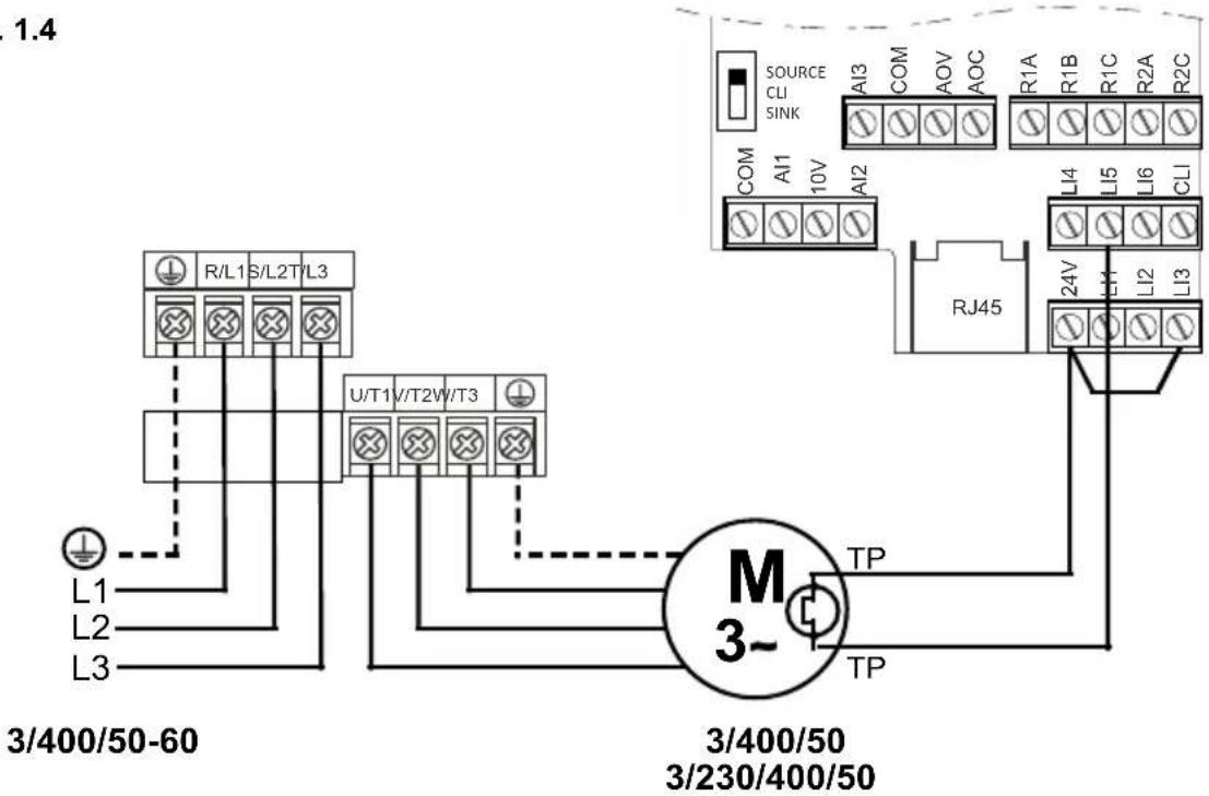
Fig. 2.1
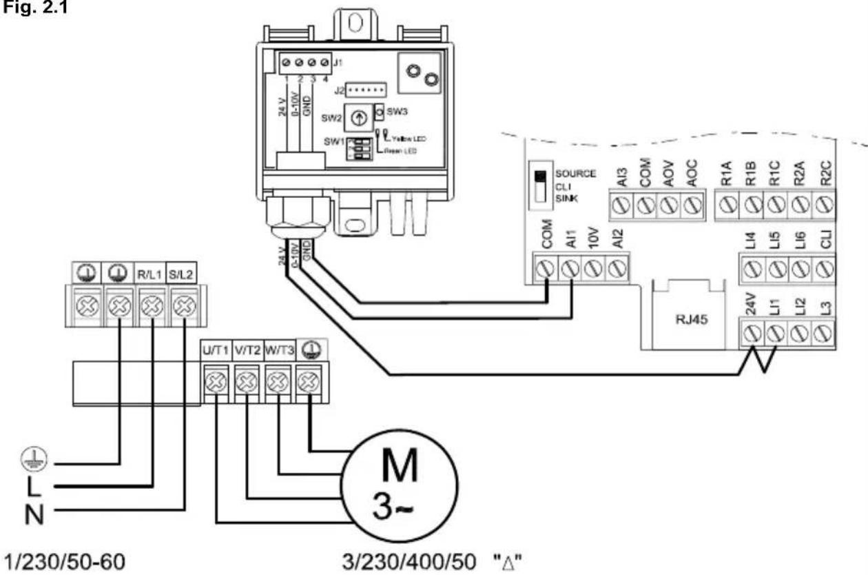
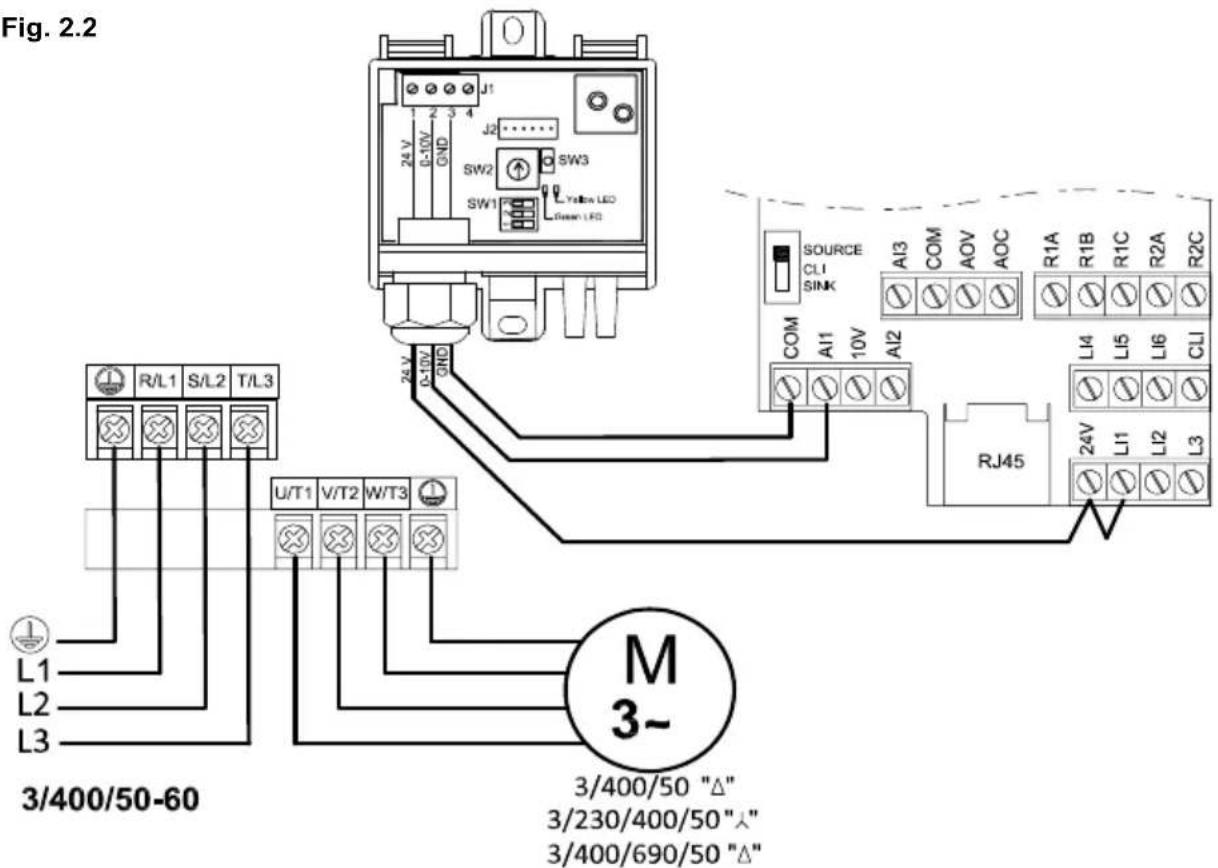
Fig. 2.3
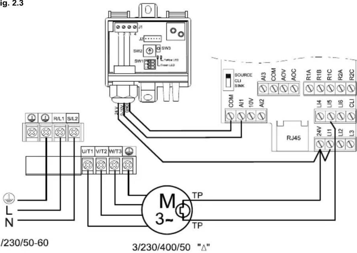
Fig. 2.4
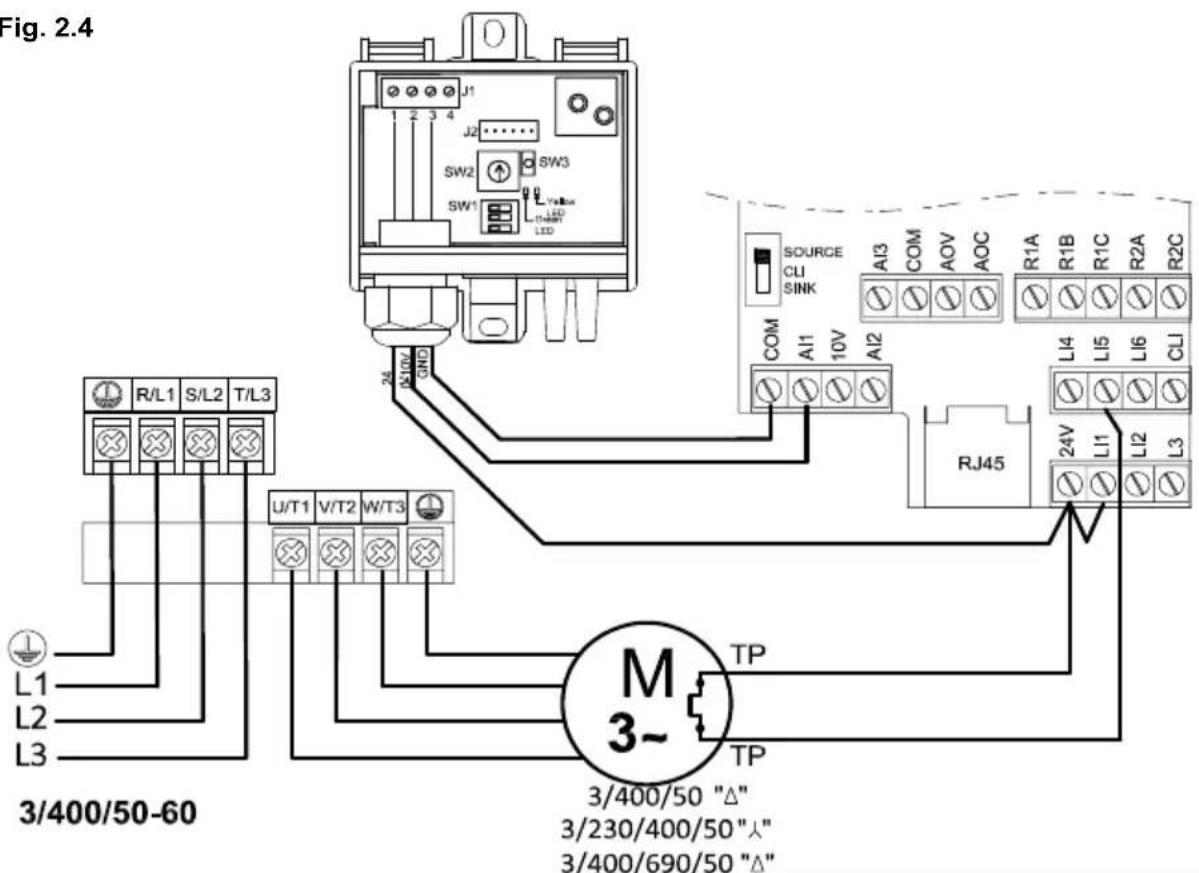
Fig. 3.1
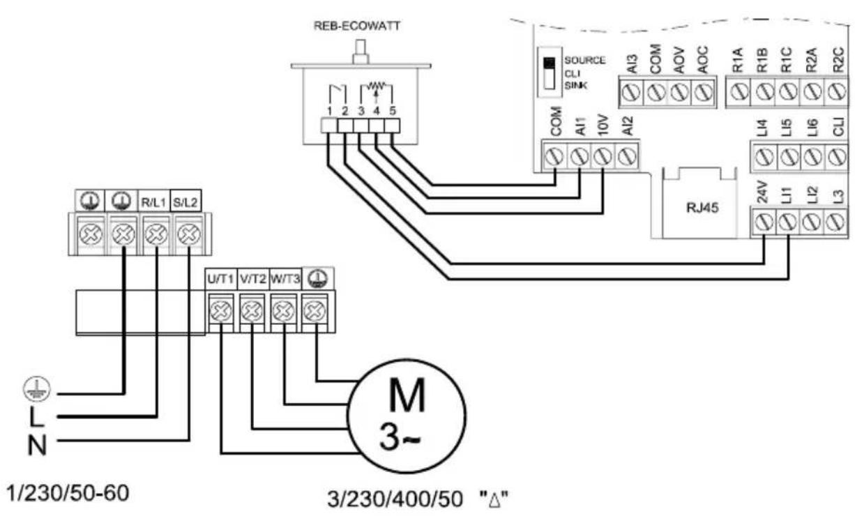
Fig. 3.2
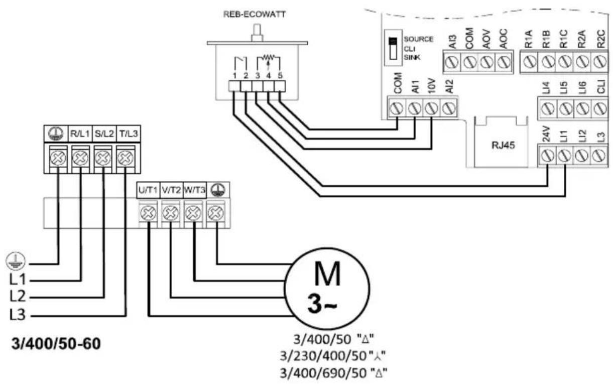
Fig. 3.3
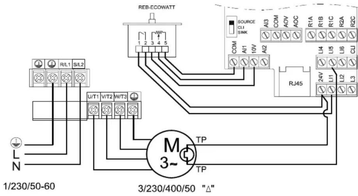
Fig. 3.4
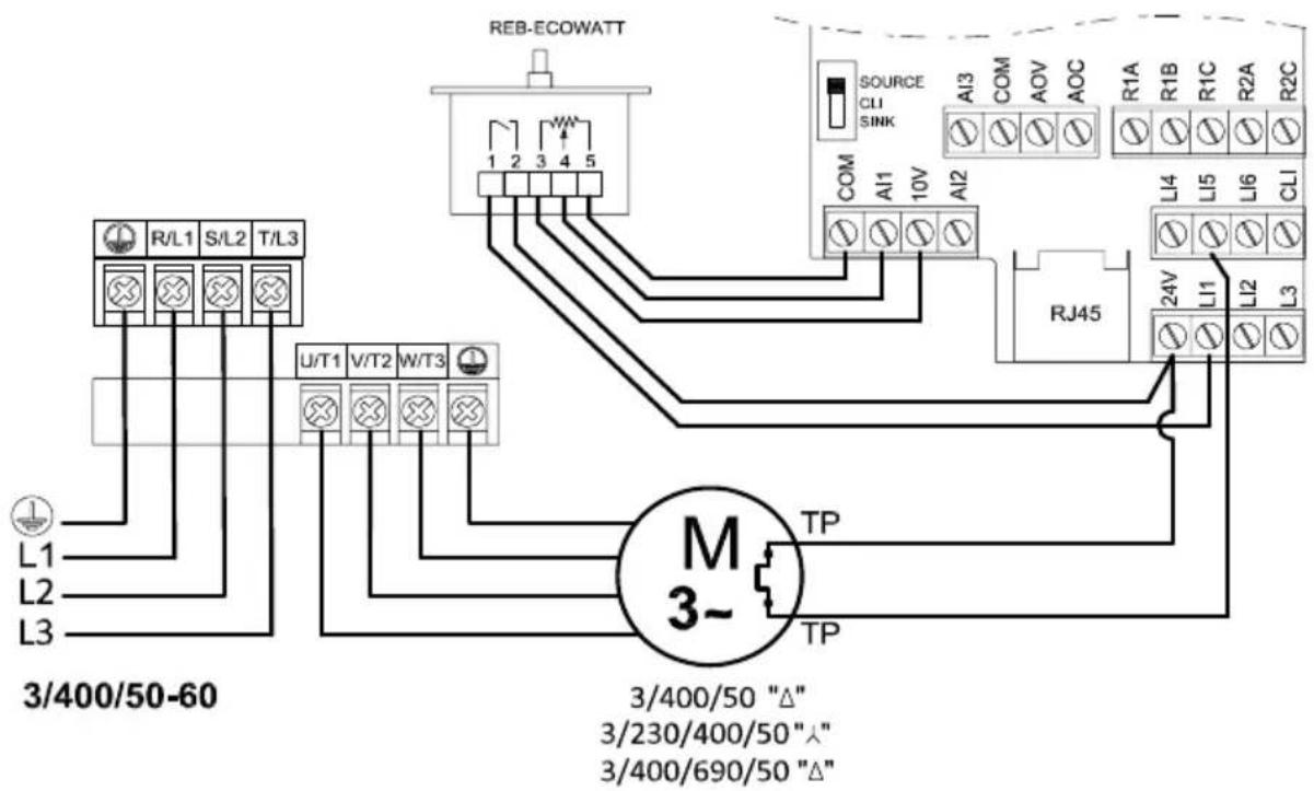
Fig. 4.1
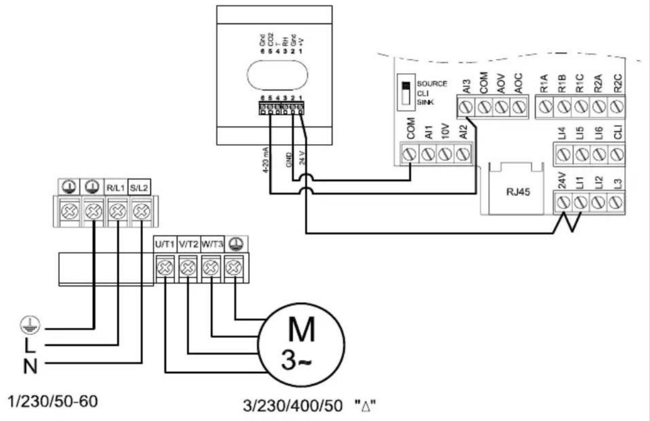
Fig. 4.2
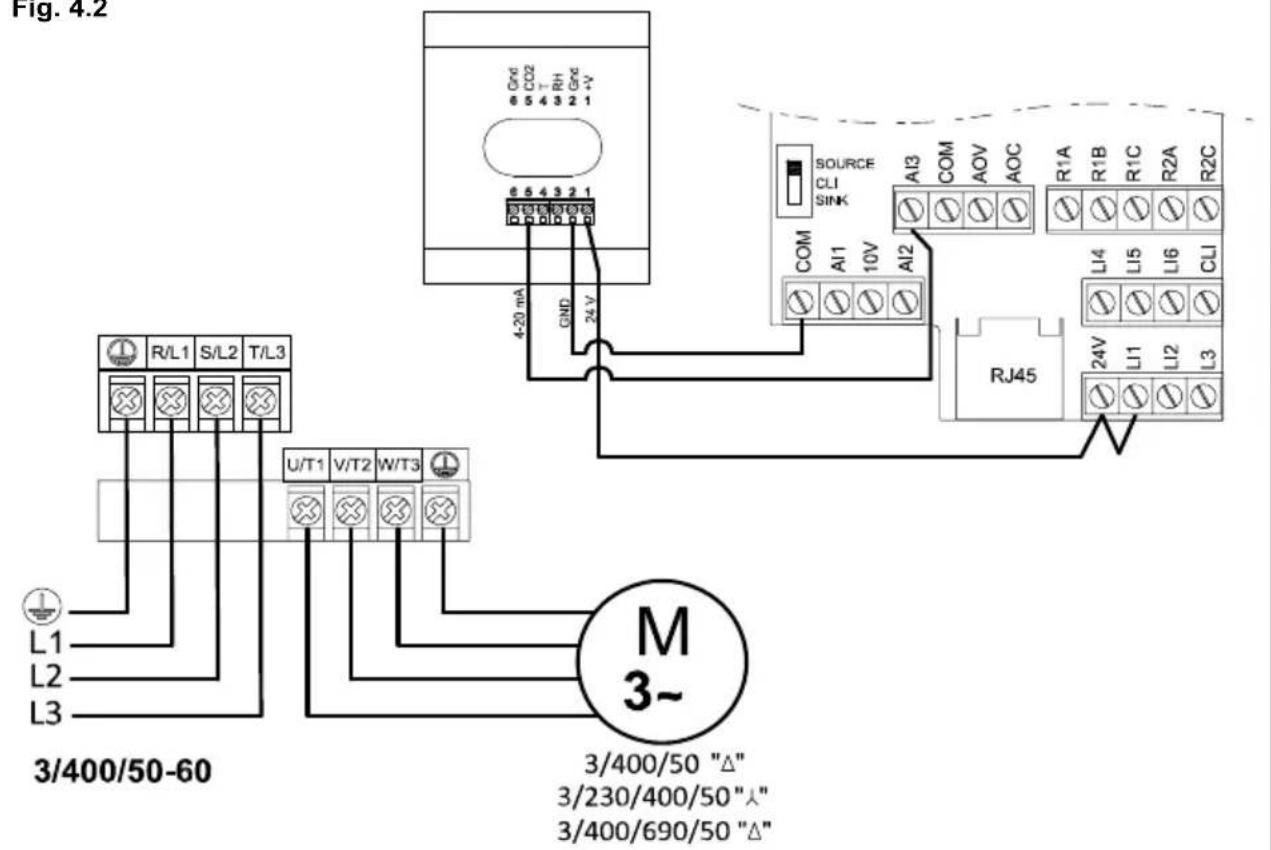
Fig. 4.3
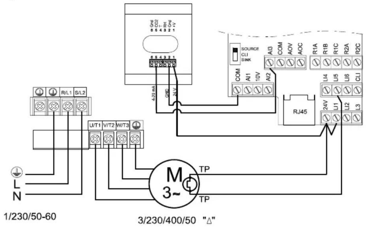
Fig. 4.4
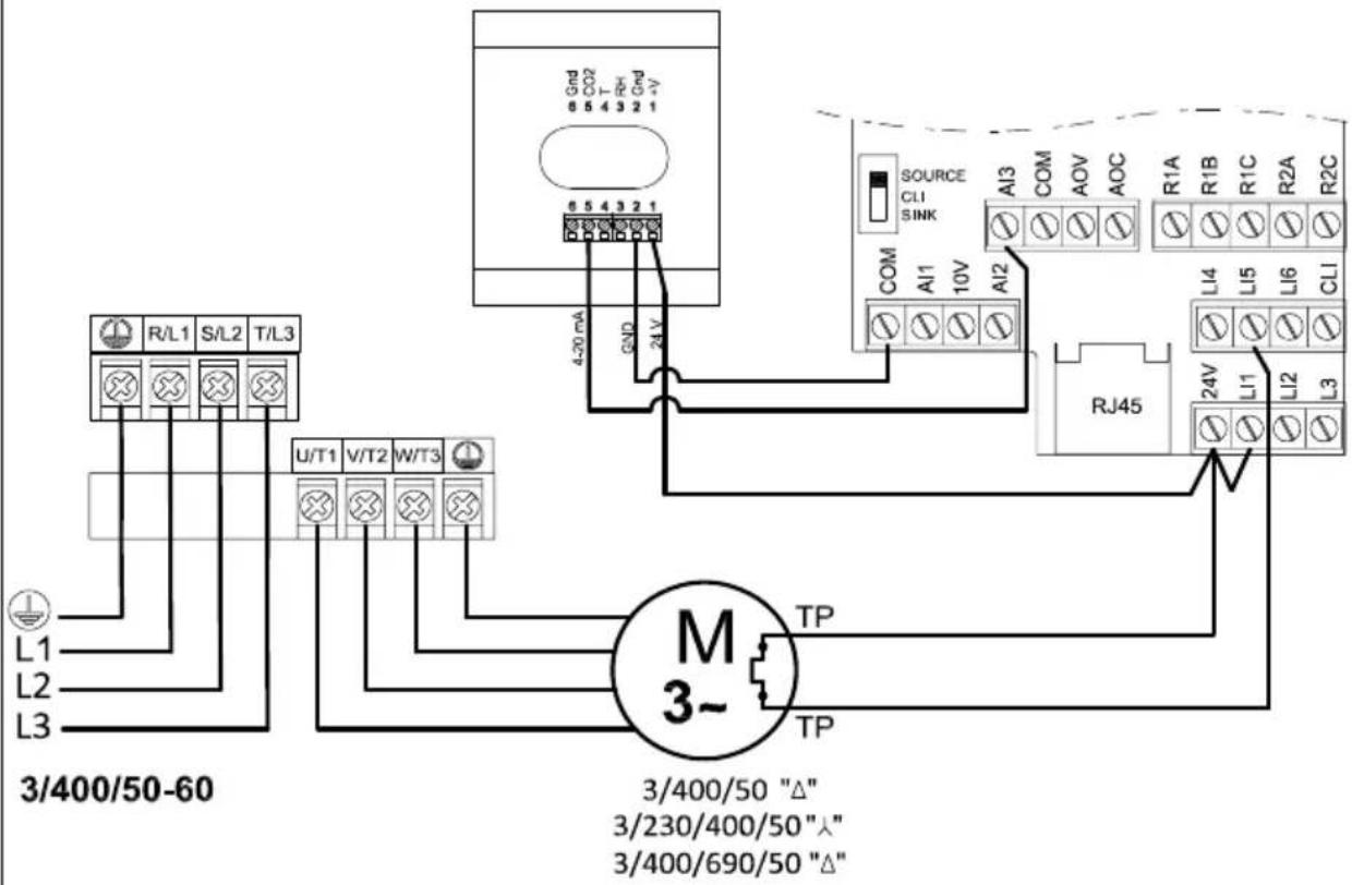
Fig. 5.1
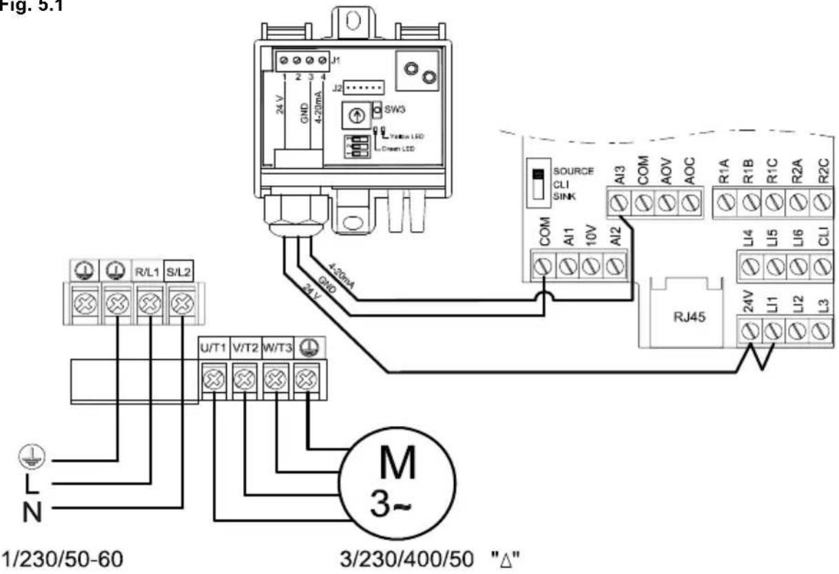
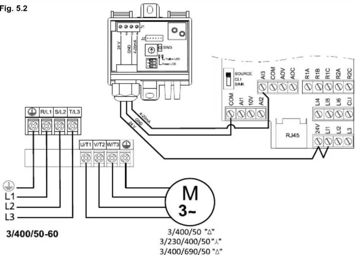
Fig. 5.3

- ESPAÑOL
- INDICE
- RECOMMENDATIONS
- Transport and handling
- Important for your safety and the safety of users
- Safety during Installation
- Maintenance
- Recycling
- GENERAL INFORMATION
- Cable for connection to the electrical supply
- Inverter reconfiguration
- Step 1. Unlock the inverter
- Step 2. Enter programming mode
- Manual reset – Automatic reset
- IMPORTANT RISK OF ELECTROCUTION RISK OF SERIOUS INJURY
- Changing the minimum/ maximum speed
- Preparing the motor thermal protection
- IMPORTANT
- RISK OF ELECTROCUTION
- RISK OF SERIOUS INJURY
- To achieve theStart/stop function with an external switch
- STANDARD APPLICATIONS OF THE INVERTER (without reconfiguring the inverter)
- MANUAL PROPORTIONAL CONTROL WITH BUILT IN POTENTIOMETER
- Features
- Wiring diagram
- USE OF THE INVERTER IN PRESSURISED STAIRWELL SYSTEMS
- Features
- Installation diagram
- Wiring diagram
- APPLICATIONS THAT REQUIRE RECONFIGURATION OF THE INVERTER
- MANUAL PROPORTIONAL CONTROL WITH REB-ECOWATT REMOTE POTENTIOMETER
- Features
- Wiring diagram
- AUTOMATIC PROPORTIONAL CONTROL WITH A 4-20 mA SIGNAL FROM AN EXTERNAL ANALOGUE SENSOR (CO2, TEMPERATURE OR RELATIVE HUMIDITY)
- Features
- Wiring diagram
- PI CONTROL IN CONSTANT PRESSURE / AIRVOLUME SYSTEMS WITH AN EXTERNAL ANALOGUE SENSOR AND 0-10V SENSOR
- Features
- Constant Air Volume (CAV)
- Constant Pressure (COP)
- Installation diagram
- Constant Flow Installation Diagram
- Inverter reconfiguration
- Step 3. Reconfigure range in sensor
- Wiring diagram
- PI CONTROL IN CONSTANT PRESSURE / AIRVOLUME SYSTEMS WITH AN EXTERNAL ANALOG SENSOR AND 4-20Ma SENSOR
- Features
- Wiring diagram
- FRANÇAIS
- SOMMAIRE
- RECOMMENDATIONS 32
- INFORMATION GENERALE 33
- Pression Constante (COP)
Brand : Soler & Palau
Model : VFTM320 IP66
Category : Frequency converter