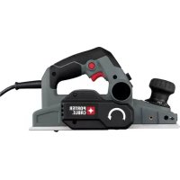
PC60THP - Plane Porter-Cable - Free user manual and instructions
Find the device manual for free PC60THP Porter-Cable in PDF.


| Product Type | Electric Planer |
| Brand | Porter-Cable |
| Model | PC60THP |
| Power Supply | 120 V~, 6 A, 60 Hz |
| Cutting Depth | 0 to 2 mm (0-5/64 in), continuous adjustment |
| Planing Width | 82 mm (3-1/4 in) |
| No-Load Speed | 16,000 RPM (estimated) |
| Weight | 2.7 kg (6 lbs) approx. |
| Cord Length | 3 m (10 ft) approx. |
| Main Functions | Planing, rabbeting (max 12 mm), chamfering (3 grooves: 1.5 / 2.0 / 2.5 mm), lock-on continuous operation, auto-locking foot, spring-loaded hand guard |
| Included Accessories | Dust bag, vacuum adapter, wrench, rabbeting guide, 2 reversible blades (one extra set) |
| Safety | Lockable switch; wear eye, hearing and respiratory protection; do not use without hand guard; sharp blades handle with care |
| Maintenance and Cleaning | Clean the ejection chute regularly; change reversible blades; replace drive belt |
| Spare Parts and Repairability | Identical parts required; repair only by authorized Porter-Cable service center (factory or authorized); no user repair |
| Warranty | Limited 3 years (2 years for battery packs); free maintenance service 1 year; 90-day money-back guarantee |
| General Information | For wood and wood-based materials; two-hand use; always unplug before adjustment or cleaning |
Frequently Asked Questions - PC60THP Porter-Cable
User questions about PC60THP Porter-Cable
0 question about this device. Answer the ones you know or ask your own.
Ask a new question about this device
Download the instructions for your Plane in PDF format for free! Find your manual PC60THP - Porter-Cable and take your electronic device back in hand. On this page are published all the documents necessary for the use of your device. PC60THP by Porter-Cable.
USER MANUAL PC60THP Porter-Cable
Instruction manual
General Power Tool Safety Warnings
⚠ WARNING: Read all safety warnings and instructions. Failure to follow the warnings and instructions may result in electric shock, fire and/or serious injury.
Save all warnings and instructions for future reference.
The term “power tool” in the warnings refers to your mains-operated (corded) power tool or battery-operated (cordless) power tool.
1) Work area safety
a) Keep work area clean and well lit. Cluttered or dark areas invite accidents
b) Do not operate power tools in explosive atmospheres, such as in the presence of flammable liquids, gases or dust. Power tools create sparks which may ignite the dust or fumes.
c) Keep children and bystanders away while operating a power tool. Distractions can cause you to lose control.
2) Electrical safety
a) Power tool plugs must match the outlet. Never modify the plug in a Do not use any adapter plugs with earthed (grounded) power tools.
Unmodified plugs and matching outlets will reduce risk of electric shock.
b) Avoid body contact with earthed or grounded surfaces such as pipes radiators, ranges and refrigerators. There is an increased risk of electric if your body is earthed or grounded.
c) Do not expose power tools to rain or wet conditions. Water entering tool will increase the risk of electric shock.
d) Do not abuse the cord. Never use the cord for carrying, pulling or unplugging the power tool. Keep cord away from heat, oil, sharp edge moving parts. Damaged or entangled cords increase the risk of electric sl
e) When operating a power tool outdoors, use an extension cord suitable outdoor use. Use of a cord suitable for outdoor use reduces the risk of shock.
f) If operating a power tool in a damp location is unavoidable, use a fault circuit interrupter (GFCI) protected supply. Use of a GFCI reduces risk of electric shock.
3) Personal safety
a) Stay alert, watch what you are doing and use common sense when operating a power tool. Do not use a power tool while you are tired under the influence of drugs, alcohol or medication. A moment of inatt while operating power tools may result in serious personal injury.
b) Use personal protective equipment. Always wear eye protection. Protect equipment such as dust mask, non-skid safety shoes, hard hat, or hearing protection used for appropriate conditions will reduce personal injuries.
c) Prevent unintentional starting. Ensure the switch is in the off-position before connecting to power source and/or battery pack, picking up or carrying the tool. Carrying power tools with your finger on the switch or energizing power tools that have the switch on invites accidents.
d) Remove any adjusting key or wrench before turning the power tool or wrench or a key left attached to a rotating part of the power tool may be personal injury.
e) Do not overreach. Keep proper footing and balance at all times. This enables better control of the power tool in unexpected situations.
f) Dress properly. Do not wear loose clothing or jewelry. Keep your hair clothing and gloves away from moving parts. Loose clothes, jewelry or hair can be caught in moving parts.
g) If devices are provided for the connection of dust extraction and col facilities, ensure these are connected and properly used. Use of dust collection can reduce dust-related hazards.
4) Power tool use and care
a) Do not force the power tool. Use the correct power tool for your application. The correct power tool will do the job better and safer at the rate for working designed.
b) Do not use the power tool if the switch does not turn it on and o power tool that cannot be controlled with the switch is dangerous and mu repaired.
c) Disconnect the plug from the power source and/or the battery pack f power tool before making any adjustments, changing accessories, or storing power tools. Such preventive safety measures reduce the risk of the power tool accidentally.
d) Store idle power tools out of the reach of children and do not allow unfamiliar with the power tool or these instructions to operate the power tool. Power tools are dangerous in the hands of untrained users.
e) Maintain power tools. Check for misalignment or binding of moving p breakage of parts and any other condition that may affect the power operation. If damaged, have the power tool repaired before use. Many accidents are caused by poorly maintained power tools.
f) Keep cutting tools sharp and clean. Properly maintained cutting tools with sharp cutting edges are less likely to bind and are easier to control.
g) Use the power tool, accessories and tool bits etc., in accordance with instructions, taking into account the working conditions and the work performed. Use of the power tool for operations different from those intended could result in a hazardous situation.
5) Service
a) Have your power tool serviced by a qualified repair person using only replacement parts. This will ensure that the safety of the power tool is
Specific Safety Rules
- Holdpowertoolbyinsulatedgrippingsurfaces,whenperforminganoperation wherethecuttingaccessorymaycontacthiddenwiringoritsowncord.Cutting
accessory contacting a "live" wire may make exposed metal parts of the power "live" and could give the operator an electric shock. - Use clamps or another practical way to secure and support the workpiece stable platform. Holding the work by hand or against your body leaves it up and may lead to loss of control.
- Wait for the cutter to stop before setting the tool down. An exposed cutter may engage the surface leading to possible loss of control and serious injury.
- To reduce the risk of injury, user must read and understand instruction manual before operating planer.
- Be sure the voltage agrees with specific data on the nameplate.
- Make certain that the switch is in the OFF position before connecting plug to a power source.
- Be sure to switch OFF immediately if tool is jammed in work.
- Be sure tool is set for correct depth before turning switch to ON.
- Be sure to use specified replacement parts only.
- Be sure tool is disconnected from power source when cleaning or making adjustments to the tool.
- Be sure to maintain tool with care. Follow instructions for lubricating and changing accessories.
- Stay alert – never operate the unit when tired or under the influence of drugs, alcohol, or medication.
- Be sure to store tool in a clean dry place after disconnecting from power source.
- Do not use in dangerous environments. Do not use near flammable substances, in damp or wet locations, or expose to rain.
-
Be sure that the blades are mounted as described in the instruction manual and check that all screws are firmly tightened before connecting unit to power source.
-
Keep air vents unobstructed for proper motor cooling.
- DO NOT lay tool down on shoe when the blades are exposed. This can chip the black
- Keep side discharge chute unobstructed at all times.
- Never reach under the tool for any reason unless it is turned off and UNPLUGGED. BLADES ARE EXPOSED AND EXTREMELY SHARP.
- Use this tool for working with wood and wood products only.
- Never operate without securely holding the front handle.
• Always operate planer with two hands. - Planer blades are extremely sharp. Handle with great care.
- Clean out your tool often, especially after heavy use.
⚠ WARNING: ALWAYS use safety glasses. Everyday eyeglasses are NOT safety glasses. Also use face or dust mask. ALWAYS WEAR CERTIFIED SAFETY EQUIPMENT:
• ANSI Z87.1 eye protection (CAN/CPA Z94.3),
• ANSI S12.6 (S3.19) hearing protection,
• NOSH/OSHA respiratory protection.
⚠ WARNING: Some dust created by power sanding, sawing, grinding, drilling, other construction activities contains chemicals known to the state of California t cancer, birth defects or other reproductive harm. Some examples of these chem
- lead from lead-based paints,
• crystalline silica from bricks and cement and other masonry products, and
• arsenic and chromium from chemically-treated lumber.
Your risk from these exposures varies, depending on how often you do this type. To reduce your exposure to these chemicals: work in a well ventilated area, with approved safety equipment, such as those dust masks that are specially dfilter out microscopic particles.
- Avoid prolonged contact with dust from power sanding, sawing, grinding, and other construction activities. Wear protective clothing and wash exposure areas with soap and water. Allowing dust to get into your mouth, eyes, or skin may promote absorption of harmful chemicals.
⚠ WARNING: Use of this tool can generate and/or disperse dust, which may be serious and permanent respiratory or other injury. Always use NOSH/OSHA appropriate respiratory protection appropriate for the dust exposure. Direct particles away from and body.
⚠ WARNING: Always wear proper personal hearing protection that conform ANSI S12.6 (S3.19) during use. Under some conditions and duration of use, this product may contribute to hearing loss.
SAFETY GUIDELINES - DEFINITIONS
It is important for you to read and understand this manual. The information it contains relates to protecting YOUR SAFETY and PREVENTING PROBLEMS. The symbols below are used to help you recognize this information.
⚠️ DANGER: Indicates an imminently hazardous situation which, if not avoided, will result in death or serious injury.
⚠ WARNING: Indicates a potentially hazardous situation which, if not avoided, could result in death or serious injury.
⚠️ CAUTION: Indicates a potentially hazardous situation which, if not avoided, may result in minor or moderate injury.
NOTICE: Used without the safety alert symbol indicates a potentially hazardous situation which, if not avoided, may result in property damage.
Symbols
- The label on your tool may include the following symbols. The symbols and their definitions are as follows:
V....volts A ....amperes
Hz......hertz W......watts
min ......minutes ......alternating\~ current
--- ....direct current n0 ....no load speed
Class I Construction ....earthing terminal
(grounded) ......safety alert symbol
☐ ......Class II Construction .../minorrpm ....revolutions or reciprocation
(double insulated) per minute
- When using an extension cord, be sure to use one heavy enough to carry the current your product will draw. An undersized cord will cause a drop in line voltage resulting in loss of power and overheating. The table shows the correct size to use depending on cord length and nameplate ampere rating. If in doubt, use the next heavier gage. The smaller the gauge number, the heavier the cord.
| Volts | Minimum Gauge for Cord Sets | |||
| Total Length of Cord in Feet | ||||
| 120V | 0-25(0-7,6m) | 26-50(7,6-15,2m) | 51-100(15,2-30,4m) | 101-150(30,4-45,7m) |
| 240V | 0-50(0-15,2m) | 51-100(15,2-30,4m) | 101-200(30,4-60,9m) | 201-300(60,9-91,4m) |
| Ampere Rating | ||||
| More Than | Not more Than | American Wire Gauge | ||
| 0 | 6 | 18 | 16 | 16 |
| 6 | 10 | 18 | 16 | 14 |
| 10 | 12 | 16 | 16 | 14 |
| 12 | 16 | 14 | 12 | Not Recommended |
SAVE THESE INSTRUCTIONS
Components
A. Trigger switch
B. Lock-on button
C. Depth adjustment knob front handle
D. Switch Handle
E. Shoe
F. Chip discharge chute
G. Chip deflector lever
H. Rabbet fence adjustment knob
I. Rabbet fence
J. Dust bag
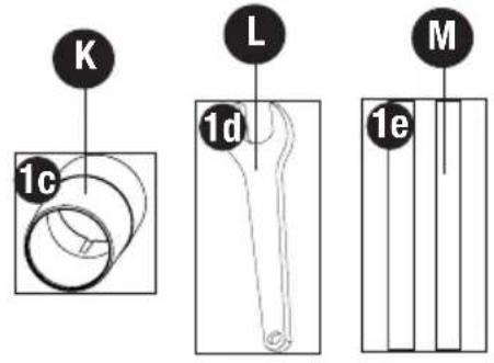
K. Vac adaptor
L. Wrench
M. Blades
N. Blade guard (not shown)


OPERATION
Switch (Figure 2)
⚠️CAUTION: Check that the tool is not locked ON before connecting it to a power supply. If the trigger switch is locked ON when the tool is connected to the power supply, it will start immediately. Damage to your tool or personal injury may result.
⚠CAUTION: Allow the tool to reach full speed before touching tool to the work surface. Lift the tool from the work surface before turning the tool off.
To start the planer, depress the trigger switch (A) in
figure 2. To turn the planer off, release the trigger switch.

Lock-On Button (Figure 2)
The tool can be locked on for continuous use. To lock the tool ON depress the trigger switch (A) and push in the lock-on button (B). Hold the lock-on button in as you gently release the trigger switch. The tool will continue to run.
To turn the tool OFF from a locked-on position, squeeze and release the trigger once.
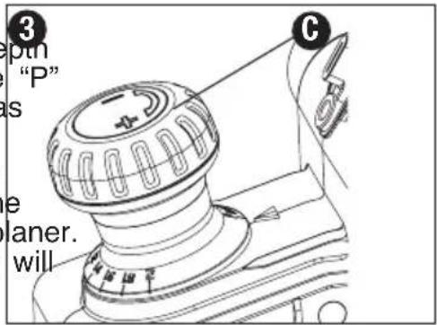
Adjusting Planing Depth (Figure 3)
⚠ WARNING: Turn off and unplug the tool before making any adjustments removing or installing accessories.
Planing depth is infinitely variable from 0 to .5/64 (2.0 mm). To adjust the cutting depth, rotate the depth adjustment knob/front handle (C) clockwise from the "P" position. The cutting depth will increase from 0 to as much as .079 in. (2.0 mm).
It is recommended that test cuts be made in scrap wood after each re-adjustment to make sure that the desired amount of wood is being removed by the plan. Several shallow passes (rather than one deep one) will produce a smoother finish.
Planing (Figures 4, 5, 6)
⚠ WARNING: Wait for the cutter to stop before setting the tool down. An exposed cutt may engage the surface leading to possible loss of control and serious injury.
⚠CAUTION: Allow the tool to reach full speed before touching tool to the work surface. Lift the tool from the work surface before turning the tool off.
Hold the planer in the correct position with one hand on the front handle (C) and the other hand on the switch handle (D) as shown in figure 4. Place the front of the shoe (E) on the surface to be planed, making certain that the cutting blades are not touching the surface. Push down firmly on the front handle of the
planer so that the front shoe is ABSOLUTELY FLAT4 on the work surface. Squeeze the trigger switch and allow the motor to reach full speed before touching the planer blades to the work surface.
Move the tool slowly into the work and maintain downward pressure to keep the planer flat. Be particularly careful to keep the tool flat at the beginning and the end of the work surface (Figures 4, 5, 6).

Planing Tip: For a smoother appearance, fasten a piece of scrap wood to the end of the piece you are planing. Don't stop planing until the cutting blades of the planer are past your work piece and into the scrap material.


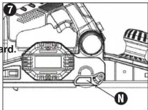
Blade Guard (Figure 7)
Ensure that the spring loaded blade guard (N) is in proper working order before using the planer.
⚠ WARNING: Cut Hazard. Do not remove guard.
Rabbet Fence (Figures 8, 9)
⚠ WARNING: Turn off and unplug the tool before making any adjustments removing or installing accessories.
⚠CAUTION: Allow the tool to reach full speed before touching tool to the work surface. Lift the tool from work surface before turning the tool off.
The rabbet fence can be installed on either side of your planer. The planer can make rabbet cuts up to .5 in. (12mm).
TO INSTALL RABBET FENCE
a. Thread the knob (I) into the hole on the side planer shown with arrow in figure 8.
b. Loosen the rabbet fence adjustment knob (H) adjust fence to desired distance.
c. Securely tighten rabbet fence adjustment knob
d. The rabbet fence should be below the planer when installed correctly as shown in figure 9.
TO MAKE A RABBET CUT
a. Turn the rabbet fence adjustment knob (H) to adjust the desired width of cut.
b. Make several cuts until the desired depth is reached.
NOTE: It will be necessary to make quite a few cuts for most rabbet applications.


Collection Bag (Figure 10)
⚠ WARNING: Turn off and unplug the tool before making any adjustments removing or installing accessories.
a. Attach bag by aligning the keyway marks on the chip discharge chute and the bag frame. Attach bag (J) to either side of chip discharge chute (F). Empty bag often to prevent clogging. b. To prevent chips from coming out opposite side of chip discharge chute, move chip deflector lever (G) to the opposite side of the bag.

Vacuum Adaptor (Figure 11)
⚠ WARNING: Turn off and unplug the tool before making any adjustments or removing or installing accessories.
a. Slide the vac adaptor (K) over the chip discharge chute (F).
b. Connect a vacuum cleaner hose (not included) to the adaptor.
c. To prevent chips from coming out opposite side of chip discharge chute, move chip deflector lever (G) to the opposite side of the adaptor.

To Change Blades (Figure 12)
⚠ WARNING: Turn off and unplug the tool before making any adjustments removing or installing accessories.
⚠ WARNING: Cut Hazard. Planer blades are sharp and must be handled with NOTE: The PC60THP has two blades, one on each side of the blade drum. Any operation or adjustment should be made to both blades. The cutting blades provided with this tool are reversible. An extra set of blades is included.
To Remove Blade from Planer
a. Place planer upside down as shown in figure b. Loosen the three nuts (N) using the wrench supplied.
c. Rotate the blade guard (O) downward. Careful remove the blade (M) by sliding it out of the holder. A piece of wood may be used for this purpose.
d. Reverse the blade so that the unused side comes in position. If both sides are worn, the blade must be replaced.

To Reinstall Blade
a. Slide the blade sideways into the holder until it is against the end stop. Blade groove must be toward back of unit.
b. Securely tighten the three nuts using the wrench supplied.
c. Rotate the blade drum 180 degrees and repeat for other blade.
d. Always replace both blades.
Parking Foot (Figure 13)
Your planer is equipped with a parking foot (P) that automatically lowers into place when the tool is lifted from the work surface. When planing, the parking raises as the tool is pushed forward. When the parking foot is lowered, the planer can set on the surface without the blade touching.

⚠️ CAUTION: Do not lock the trigger switch on and engage the parking foot. The vibration of the running motor will cause the planer to move, possibly falling from the w piece.
Edge Chamfering (Figure 14)
Your planer has three precision machined chamfer grooves 1.5mm, 2.0mm and 2.5mm (Q). They are located in the front shoe and are used for planing along a corner of the material (figure 14).
a. Adjust to desired depth of cut.
b. Place groove (Q) over edge of material.
c. Apply weight to front of shoe so groove is flat on material edge.
d. Hold tool with both hands keeping pressure on front handle.
Note: It's a good idea to try a piece of scrap wood before doing finish work.

Drive Belt (Figure 15)
⚠ WARNING: Turn off and unplug the tool before making any adjustments removing or installing accessories.
To Replace Belt
a. Loosen the three screws shown in figure and remove the belt cover.
b. Remove old belt.
c. Place new belt over front pulley then rotate clockwise while pushing belt onto back pulley.
d. Attach belt cover and securely tighten screws.

Maintenance
Cleaning
⚠ WARNING: Turn off and unplug unit before cleaning chip discharge chute Clean the chip discharge chute (F) regularly. ALWAYS WEAR SAFETY GLASSES.
⚠CAUTION: Never use solvents or other harsh chemicals for cleaning the non-metallic parts of the tool.
Use only mild soap and damp cloth to clean the tool. Never let any liquid get inside the tool; never immerse any part of the tool into a liquid.
TROUBLESHOOTING
Problem Possible Cause Possible Solution
- Unit will not start. • Cord not plugged in. • Plug tool into a working outlet.
- Circuit fuse is blown.
- Replace circuit fuse. (If the product repeatedly causes the circuit fuse to blow, discontinue use immediately and have it serviced at a Porter Cable service center or authorized servicer.)
- Circuit breaker is tripped.
- Reset circuit breaker. (If the product repeatedly causes the circuit breaker to trip, discontinue use immediately and have it serviced at a Porter Cable service center or authorized servicer.)
- Cord or switch is damaged.
- Have cord or switch replaced at a Porter Cable Service Center or Authorized Servicer
For assistance with your product, visit our website at www.portercable.com for a list of service centers, or call the PorterCable Customer Care Center at (888) 848-5175.
REPLACEMENT PARTS
Use only identical replacement parts. For a parts list or to order parts, visit our service www.portercable.com. You can also order parts from your nearest PORTER-CABLE Fac Service Center or PORTER-CABLE Authorized Warranty Service Center. Or, you can ca Customer Care Center at (888) 848-5175.
SERVICE AND REPAIRS
All quality tools will eventually require servicing and/or replacement of parts. For information PORTER-CABLE, its factory service centers or authorized warranty service centers, visit website at www.portercable.com or call our Customer Care Center at (888) 848-5175. All made by our service centers are fully guaranteed against defective material and work; cannot guarantee repairs made or attempted by others.
You can also write to us for information at PORTER-CABLE, 4825 Highway 45 North, Tennessee 38305, (888) 848-5175 - Attention: Product Service. Be sure to include all of information shown on the nameplate of your tool (model number, type, serial number, e
ACCESSORIES
⚠ WARNING: Since accessories, other than those offered by PORTER-CABLE, have not been tested with this product, use of such accessories with this tool could be hazardous. To reduce the risk of injury, only PORTER-CABLE recommended accessories should be used with this product.
A complete line of accessories is available from your PORTER-CABLE Factory Service Center or a PORTER-CABLE Authorized Warranty Service Center. Please visit our Web Site www.portercable.com for a catalog or for the name of your nearest supplier.
THREE YEAR LIMITED WARRANTY
PORTER-CABLE will repair or replace, without charge, any defects due to faulty materials or workmanship for three years from the date of purchase for tools (two years for batteries). This warranty does not cover part failure due to normal wear or tool abuse. For further detail of warranty coverage and warranty repair information, visit www.portercable.com or call (888) 848-5175. This warranty does not apply to accessories or damage caused where repairs have been made or attempted by others. This warranty gives you specific legal rights and you may have other rights which vary in certain states or provinces.
In addition to the warranty, PORTER-CABLE tools are covered by our:
1 YEAR FREE SERVICE: PORTER-CABLE will maintain the tool and replace worn parts caused by normal use, for free, any time during the first year after purchase.
90 DAY MONEY BACK GUARANTEE: If you are not completely satisfied with the performance of your PORTER-CABLE Power Tool for any reason, you can return it within 90 days from the date of purchase with a receipt for a full refund – no questions
LATIN AMERICA: This warranty does not apply to products sold in Latin America. For products sold in Latin America, see country specific
warranty information contained in the packaging, call the local company or see website for warranty information.
To register your tool for warranty service visit our website at www.portercable.com
WARNING LABEL REPLACEMENT
If your warning labels become illegible or are missing, call (888) 848-5175 for a free replacement.
The following are PORTER-CABLE trademarks for one or more power tools and access gray and black color scheme; a “four point star” design; and three contrasting/outlined lines stripes. The following are also trademarks for one or more PORTER-CABLE and Delta | Les éléments ci-dessous sont des marques de commerce des outils et des accessoires. PORTER-CABLE : un agencement de couleurs grise et noire; un motif d’« étoile à quatre » et trois bandes longitudinales contrastantes/à contours. Les marques suivantes sont égés des marques de commerce se rapportant à un ou plusieurs produits PORTER-CABLE o Las siguientes son marcas comerciales PORTER-CABLE que distinguen a una o más herramientas y accesorios: un gráfico de color gris y negro; un diseño de “estrella de c puntas” y tres franjas longitudinales contrastantes/delineadas. Las siguientes también son comerciales para uno o más productos de PORTER-CABLE y Delta: 2 BY 4®, 890™, A America®, AIRBOSS™, Auto-Set®, B.O.S.S.®, Bammer®, Biesemeyer®, Builders Saw®, Air®, Charge Air Pro®, CONTRACTOR SUPERDUTY®, Contractor’s Saw®, Delta®, DELLA Industrial®, DELTA MACHINERY & DESIGN™, Delta Shopmaster and Design®, Deltacraft®, DELTAGRAM®, Do It. Feel It.®, DUAL LASERLOCAND DESIGN®, EASYAI EASYAIR TO GO™, ENDURADIAMOND®, Ex-Cell®, Front Bevel Lock®, Get Yours Whit Sun Shines®, Grip to Fit®, GRIPVAC™, GTF®, HICKORY WOODWORKING®, Homecraft FRAMER HIGH PRESSURE®, IMPACT SERIES™, Innovation That Works®, Jet-Lock®, Boss®, Kickstand®, LASERLOC®, LONG-LASTING WORK LIFE®, MAX FORCE™, MAX LIFE®, Micro-Set®, Midi-Lathe®, Monsoon®, MONSTER-CARBIDE™, Network®, OLDHAI Omnijig®, PC EDGE®, Performance Crew™, Performance Gear®, Pocket Cutter®, Portal Porta-Plane®, PORTER-CABLE®, PORTER-CABLE Professional Power Tools®, Powerba POZI-STOP™, Pressure Wave®, PRO 4000®, Proair®, Quicksand and Design®, Quicksand QUIET DRIVE TECHNOLOGY™, QUIET DRIVE TECHNOLOGY AND DESIGN™, Quik-Change®, QUIK-TILT®, RAPID-RELEASE™, RAZOR®, Redefining Performance®, Riptide Safe Guard II®, Sand Trap and Design®, Sanding Center®, Saw Boss®, Shop Boss®, Site Boss®, Speed-Bloc®, Speedmatic®, Stair Ease®, Steel Driver Series®, SUPERDUT & DESIGN®, THE AMERICAN WOODSHOP®, THE PROFESSIONAL EDGE®, Thin-Line Tiger Saw®, TIGERCLAW®, TIGERCLAW AND DESIGN®, Torq-Buster®, TRU-MATCH® Square®, Twinlaser®, Unifence®, Uniguard®, UNIRIP®, UNISAW®, UNITED STATES SA Veri-Set®, Versa-Feeder®, VIPER®, VT™, VT RAZOR™, Water Driver®, WATER VROCC Waveform®, Whisper Series®, X5®, YOUR ACHIEVEMENT. OUR TOOLS.®
Trademarks noted with ® are registered in the United States Patent and Trademark Offi also be registered in other countries. Other trademarks may apply. Les marques de con suivies du symbole ® sont enregistrées auprès du United States Patent and Trademark peuvent être enregistrées dans d'autres pays. D'autres marques de commerce peuvent être applicables. Las marcas comerciales con el símbolo ® están registradas en la Ofici patentes y marcas comerciales de Estados Unidos (United States Patent and Trademark también pueden estar registradas en otros países. Posiblemente se apliquen otras marc comerciales registradas.
PORTER CABLE.
4825 Highway 45
North Jackson, TN 38305
(888) 848-5175
www.portercable.com
PORTER CABLE®
Raboteuse de 6,0 A


FONCTIONNEMENT
Pare-main (figure 7)
Les éléments ci-dessous sont des marques de commerce des outils et des accessoires PORTER-CABLE : un agencement de couleurs grise et noire; un motif d' « étoile à qua et trois bandes longitudinales contrastantes/à contours. Les marques suivantes sont éga marques de commerce se rapportant à un ou plusieurs produits PORTER-CABLE ou De 4®, 890™, Air America®, AIRBOSS™, Auto-Set®, B.O.S.S.®, Bammer®, Biesemeyer®, Saw®, Charge Air®, ChargeAir Pro®, CONTRACTOR SUPERDUTY®, Contractor's Saw® Delta®, DELTA®, Delta Industrial®, DELTAMACHINERY & DESIGN™, Delta Shopmaster Design®, Delta X5®, Deltacraft®, DELTAGRAM®, Do It. Feel It.®, DUAL LASERLOC AI DESIGN®, EASYAIR®, EASY AIR TO GO™, ENDURADIAMOND®, Ex-Cell®, Front Bev Lock®, Get Yours While the Sun Shines®, Grip to Fit®, GRIPVAC™, GTF®, HICKORY WOODWORKING®, Homecraft®, HP FRAMER HIGH PRESSURE®, IMPACT SERIES™ Innovation That Works®, Jet-Lock®, Job Boss®, Kickstand®, LASERLOC®, LONG-LAST WORK LIFE®, MAX FORCE™, MAX LIFE®, Micro-Set®, Midi-Lathe®, Monsoon®, MON CARBIDE™ Network®, OLDHAM®, Omnijig®, PC EDGE®, Performance Crew™, Perform Gear®, Pocket Cutter®, Porta-Band®, Porta-Plane®, PORTER-CABLE®, PORTER-CABL Professional Power Tools®, Powerback®, POZI-STOP™, Pressure Wave®, PRO 4000®, Quicksand and Design®, Quickset II®, QUIET DRIVE TECHNOLOGY™, QUIET DRIVE TECHNOLOGY AND DESIGN™, Quik-Change®, QUIK-TILT®, RAPID-RELEASE™, RAZO Redefining Performance®, Riptide®, Safe Guard II®, Sand Trap and Design®, Sanding Saw Boss®, Shop Boss®, Sidekick®, Site Boss®, Speed-Bloc®, Speedmatic®, Stair East Driver Series®, SUPERDUTY®, T4 & DESIGN®, THEAMERICAN WOODSHOP®, THE PROFESSIONAL EDGE®, Thin-Line®, Tiger Saw®, TIGERCLAW®, TIGERCLAW AND DESIGN®, Torq-Buster®, TRU-MATCH®, T-Square®, Twinlaser®, Unifence®, Uniguard® UNIRIP®, UNISAW®, UNITED STATES SAW®, Veri-Set®, Versa-Feeder®, VIPER®, VT RAZOR™, Water Driver®, WATER VROOM®, Waveform®, Whisper Series®, X5®, YOU ACHIEVEMENT. OUR TOOLS.®
Manual de'instrucciones
www.portercable.com
Mantenimiento
Limpieza
Las siguientes son marcas comerciales PORTER-CABLE que distinguen a una o más herramientas y accesorios: un gráfico de color gris y negro; un diseño de “estrella de puntas” y tres franjas longitudinales contrastantes/delineadas. Las siguientes también son comerciales para uno o más productos de PORTER-CABLE y Delta: 2 BY 4®, 890™, America®, AIRBOSS™, Auto-Set®, B.O.S.S.®, Bammer®, Biesemeyer®, Builders Saw®, Air®, Charge Air Pro®, CONTRACTOR SUPERDUTY®, Contractor's Saw®, Delta®, DEL Delta Industrial®, DELTAMACHINERY & DESIGN™, Delta Shopmaster and Design®, De Deltacraft®, DELTAGRAM®, Do It. Feel It.®, DUAL LASERLOC AND DESIGN®, EASYA EASYAIR TO GO™, ENDURADIAMOND®, Ex-Cell®, Front Bevel Lock®, Get Yours Wh Sun Shines®, Grip to Fit®, GRIPVAC™, GTF®, HICKORY WOODWORKING®, Homecraft FRAMER HIGH PRESSURE®, IMPACT SERIES™, Innovation That Works®, Jet-Lock®, Boss®, Kickstand®, LASERLOC®, LONG-LASTING WORK LIFE®, MAX FORCE™, MAX LIFE®, Micro-Set®, Midi-Lathe®, Monsoon®, MONSTER-CARBIDE™, Network®, OLDHA Omnijig®, PC EDGE®, Performance Crew™, Performance Gear®, Pocket Cutter®, Porta-Plane®, PORTER-CABLE®, PORTER-CABLE Professional Power Tools®, Powerba POZI-STOP™, Pressure Wave®, PRO 4000®, Proair®, Quicksand and Design®, Quicks QUIET DRIVE TECHNOLOGY™, QUIET DRIVE TECHNOLOGYAND DESIGN™, Quik-Change®, QUIK-TILT®, RAPID-RELEASE™, RAZOR®, Redefining Performance®, Riptide Safe Guard II®, Sand Trap and Design®, Sanding Center®, Saw Boss®, Shop Boss®, Site Boss®, Speed-Bloc®, Speedmatic®, Stair Ease®, Steel Driver Series®, SUPERDUT DESIGN®, THEAMERICAN WOODSHOP®, THE PROFESSIONAL EDGE®, Thin-Line®, Saw®, TIGERCLAW®, TIGERCLAWAND DESIGN®, Torq-Buster®, TRU-MATCH®, T-Squ Twinlaser®, Unifence®, Uniguard®, UNIRIP®, UNISAW®, UNITED STATES SAW®, Veri Versa-Feeder®, VIPER®, VT™, VT RAZOR™, Water Driver®, WATER VROOM®, Wave Whisper Series®, X5®, YOURACHIEVEMENT. OUR TOOLS.®
4825 Highway 45 North
Jackson, Tennessee 38305
(888)848-5175
www.portercable.com

- GENERAL POWER TOOL SAFETY WARNINGS
- SPECIFIC SAFETY RULES
- SAFETY GUIDELINES - DEFINITIONS
- SYMBOLS
- SAVE THESE INSTRUCTIONS
- COMPONENTS
- OPERATION
- SWITCH (FIGURE 2)
- LOCK-ON BUTTON (FIGURE 2)
- ADJUSTING PLANING DEPTH (FIGURE 3)
- PLANING (FIGURES 4, 5, 6)
- BLADE GUARD (FIGURE 7)
- RABBET FENCE (FIGURES 8, 9)
- TO INSTALL RABBET FENCE
- TO MAKE A RABBET CUT
- COLLECTION BAG (FIGURE 10)
- VACUUM ADAPTOR (FIGURE 11)
- TO CHANGE BLADES (FIGURE 12)
- TO REMOVE BLADE FROM PLANER
- TO REINSTALL BLADE
- PARKING FOOT (FIGURE 13)
- EDGE CHAMFERING (FIGURE 14)
- DRIVE BELT (FIGURE 15)
- TO REPLACE BELT
- MAINTENANCE
- CLEANING
- TROUBLESHOOTING
- PROBLEM POSSIBLE CAUSE POSSIBLE SOLUTION
- REPLACEMENT PARTS
- SERVICE AND REPAIRS
- ACCESSORIES
- THREE YEAR LIMITED WARRANTY
- WARNING LABEL REPLACEMENT
- PORTER CABLE
- PORTER CABLE®
- FONCTIONNEMENT
- PARE-MAIN (FIGURE 7)
- MANTENIMIENTO
- LIMPIEZA
Brand : Porter-Cable
Model : PC60THP
Category : Plane